[Trade Journal]
Publication: The Electrician & Electrical Engineer
New York, NY, United States
vol. 4, p. 207-208, col. 1-2
THE CONSTRUCTION OF LINES FOR ELECTRIC
CIRCUITS.
BY THOMAS D. LOCKWOOD.
(Continued from page 173.)
There are one or two other points on the attachment of insulators which it may be well to refer to.
If it is found that any insulator, when attached to a bracket, touches with its edge the shoulder of the bracket, that bracket should at once be discarded, as all the conditions of a bad escape are thus prepared. Before such a bracket is used it should be shaved off so that there is no contact except on the attaching screw; moreover, neither glass insulators, brackets nor rubber hooks should be attached horizontally, as such a method of attachment is simply preparing an easy way for a driving rain to enter the insulator possibly to leave water standing in the hollows thereof.
STRINGING WIRE ON POLE-LINES.
The size of wire being decided upon, the coils are mounted horizontally on suitable reels, which may be placed in a wagon, and drawn by a horse from pole to pole, or which, in the case of more modest constructors, may be carried on a hand-barrow, or even carried on a short pole. The last named expedient seems, however, to be more crude than is necessary, as almost any amateur constructor can make a suitable reel, and mount it on a wheel or hand-barrow.
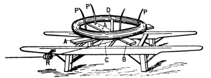 |
| Figure 12. |
The reel shown in the figure is a very handy one, and can easily be managed by one man.
The two cross-pieces, A & B, should each be about three feet long, two inches thick and three wide, and they rest on the stationary cross-bar,c, by means of the iron centre-pin, D, which may be about six inches high, and an inch and a half thick. The centre hole should be fitted with a bushing of iron; if the hole through the wood is made larger than the pin, a couple of iron plates may be made to serve instead of the bushing; they must be bored at the centre to fit the pin, and then fastened to the upper and lower surfaces of the cross-pieces, so that they will revolve easily on the pin.
A number of holes, h, may be bored in the cross-pieces, so that the pins, p, may be changed to fit reels of various sizes. A metal or glass ring, R, may be attached to an iron clamp, and fastened to the side of the barrow for the wire to pass through. Lieut. Swift, in his recent work, "The Practical Telegrapher," suggests for this purpose an ordinary glass insulator, with the top punched out. The number of men required to string wire varies almost as much as any other feature of the business. I have strung wire with but two men one to climb, and one to watch the reel and pull up; but I have also worked a force with as many as six climbers, and it is needless to say that in the last case the work was done much quicker, and in some degree better, as many times circumstances occur in which a number of hands can be economically employed. Each climber requires a pair of good pliers, a pair of climbing spurs, and a supply of tie wires.
The reel is advanced along the line for some distance ahead, and before any wire is attached the person in charge should have the wire laid at the foot of the poles, and examined for faults and unsoldered joints, as no such defect ought to pass unremedied. When the end of the coil is reached, the beginning of the next should be jointed to it while a considerable length of the former is still on the ground.
The wire thus examined may be now picked up by the polemen, who, many or few, should all climb at once, the wire being thrown over their arms.
The tie-wire is made to embrace the insulator in the wire groove, and the line-wire is then placed in the opposite side of the groove over the ends of the tie-wire, which are then turned upward. Before completing the attachment the line-wire must be tightened up by the man or men in charge below.
This is best done with a block and tackle, but quite frequently has to be done by hand. When it is pulled sufficiently taut, the climber gives each end of the tie-wire a turn and a half around the line-wire, and then cuts off the ends, thus completing the attachment.
TIE-WIRES.
Tie-wires may be cut from the wire to be strung, and need not, as a rule, be more than 12 or 14 inches long. If the line conductor is a copper wire, the tie-wire must also be of copper; this is a most important point, and to use iron tie-wires for copper lines is simply to prepare future trouble, as galvanic action may be expected from such a combination. When a copper line is being attached, great care must also be taken not to twist the tie-wires too tightly, as the copper wire is liable to be cut into or otherwise damaged. A number of methods have recently been adopted to some extent with copper wire, in which the tie-wire is made to support the line-wire altogether, and is bound round it, as well as round the insulator; but, if well done, I regard the old-fashioned method as being equally serviceable.
STRAIN.
Very rarely in the United States is sufficient attention paid to the matter of strain, and yet it is one of the most important in line construction. The degree of tautness with which a line-wire is originally stretched frequently determines its durability. If a wire is pulled up too tight, it will sooner or later break; if left too slack, it will cross with others. How is the proper mean to be arrived at? This subject has been brought to an exact science in England, and we shall do well to profit by the practice which obtains there.
The maximum tension of any span should be one-third of the breaking strain. No. 8 iron wire, for example, has a breaking strain of 1,200 pounds, and the tension with which it is drawn up should therefore not exceed 400 pounds. No. 12 iron wire has a breaking strain of about 510 pounds, and should not be pulled up with a greater tension than 170 pounds.
But it will be objected, How is it possible to know what tension is given to a span without wasting valuable time, and putting more work into it than it is worth? This is where the results of experience are utilized.
It has been found that the dip of a wire, by which is meant the difference between the lowest point of the span and the level of the supports, is just about 24 inches in a span of 100 yards, when the tension is one-third of the breaking strain, and knowing this, we can readily apply it to spans of any length. The dip increases, not with the distance between the poles, but as the square of the number of times that the distance is increased. If, for example, in a span of 50 yards we have a dip of one foot, for double that distance, 100 yards, the dip will be 2x2, or four feet; for four times the distance, or 200 yards, the dip would be 4x4, or 16 feet. Therefore, if we wish to know what the dip of any span should be, on the standard of 24 feet to the 100-yard span, we simply multiply the original dip by the square of the length of the proposed span, and divide by the square of the length of the original span. Suppose, for example, that I wish to know the dip for a span of 80 yards, I multiply the standard dip, 24, by the square of 80, and divide by the square of 100, finding as a result the required dip to be approximately 15 1/2 inches.
The mathematical formula is:
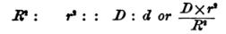 |
R being the length in yards of the original span; r the length in yards of the proposed span; D the standard dip, and d, the proposed dip. From the above considerations I have deduced the following table:
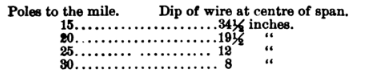 |
It must be remembered that these dimensions are the maximum figures, and that they are calculated for a temperature of 60° F. They hold good, however, for all sizes of iron wire alike, and thus only one wire on a line of poles need be closely calculated for; the remaining wires only need to be pulled up parallel with the first. Wires strung in the summer, must be suspended a little slacker than those put up in winter, as iron wire expands about 4 1/16 inches per mile for every ten degrees of rising temperature. There is still another quite important point about strains this is, that the tension is least at the centre of the curve, and greatest near the poles. In very long spans we may avail ourselves of this fact, to advantage, by introducing a lighter wire into the middle of the span. By so doing the ends will not have so much weight to carry, while the centre will still be strong enough to resist the lessened strain of the lowest point.
An important application of these rules lies in regulating the tension with which the supporting wires of aerial cables are pulled up. In many places I have observed that such suspending wires are pulled up nearly to a level. This however, is a most injudicious practice, as a wire so pulled up is too tight, even if it had no extra weight to carry. A wire so drawn up cannot be expected to stand well, and, moreover, places far too heavy a strain on the poles or supports. Much of the strength of a wire stretched to such a degree, is taken up in holding itself together against the constant tendency which its particles have to pull apart. Furthermore, if a wire is so pulled up in mild weather, it can scarcely be expected to stand in cold weather, when the strain will be enormously increased.
When copper wire is used, a new basis for calculation must be formed, as the standard of a dip of 24 inches in a 100 yards does not hold for any other metal than iron. It is still, however, proper to adhere to the maximum tension of one-third of the breaking strain.
It is clear, then, that we must, to find the maximum strain which should be allowed to copper wire spans, first ascertain the breaking strain or tensile strength of the copper wire, then taking one-third of that, note the dip produced in a 100 yard span (or a shorter span, according to the law of squares, referred to already), under a tension of that amount, which will give a new standard for copper wire.
No. 12 B. W. G. hard copper wire is found, for example, to average a breaking strain of 566 pounds; and, therefore, should be pulled up with a maximum strain of 188 pounds.
Where a wire runs through foliage which cannot be trimmed, short pieces of heavy kerite wire may with profit be inserted in the line circuit.
JOINTS OR SPLICES.
I suppose that defective joints have given rise to more trouble in electric circuits than any other single fault. It is really surprising how much annoyance a single bad joint can produce, and how much resistance it can introduce into an otherwise good line. This is due partly to the great number of splices in a line, partly to the too frequent lack of care with which they are made, and partly to the difficulty with which an imperfect splice is located, and to the impossibility of a close inspection, when the suspected splice is about midway between two poles. It is quite obvious, therefore, that jointing is one of the most important operations which a lineman is called upon to perform, and all linemen should be carefully instructed as to the absolute necessity of nothing less than perfection in such work. Each manufacturer's joint ought to be examined, while the wire is lying at the foot of the poles, immediately before stringing, and any found defective, or even suspected, should be cut out and made over. Although more attention is now justly paid to this branch of construction, than has been the case in the past, it is to be feared that even yet the extreme importance of extra care is underrated by the majority of persons engaged in line construction. Soldering every splice adds almost indefinitely to the working capacity of a line, yet comparatively few constructors regard joint soldering as being as much a part of their work as fastening the wires properly to the insulators. The consequences of neglect are, in fact, much more disastrous and far-reaching. No unsoldered joint should ever be permitted to go into a line. No twist-joint can, if left unsoldered, long stand the oxidizing powers of the elements.
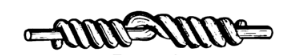 |
| Figure 13. |
The figure above well represents the characteristic American joint. It is not as neat a joint as some others, but it is easily made, hangs well together, and when thoroughly soldered constitutes a very good splice. In making it, the ends should first be brightened, and then put together and held by a vise, while each end in turn is wound tightly round the other five or six times, the turns passing close to one another, and as nearly at right angles to the wire they surround as they can be made. The extreme ends are then clipped off close, and a twist given to the middle of the joint, to bring the two wires into still more intimate contact, after which the joint is soldered and is then complete.
(To be continued.)
