[Trade Journal]
Publication: The Electrician & Electrical Engineer
New York, NY, United States
vol. 4, p. 4-5, col. 2,1-2
THE CONSTRUCTION OF LINES FOR ELECTRIC
CIRCUITS.
BY THOMAS D. LOCKWOOD.
(Continued from page 369, Vol. III.)
IT is not therefore advisable with our present knowledge to use compound aerial cables of greater length than 2 miles for telephonic exchange purposes. When cables of any length between 500 feet and 2 miles are employed, if they are of the rubber or kerite insulation, the Foucaut arrangement should be applied in some form; and finally if cables are to be used for private lines, or for any purposes not connected with telephone exchanges, and where expense is not a factor, the use of the twisted or closely adjacent metallic return is here strenuously advocated, as a much greater length of cable can thus be employed; induction being practically eliminated; and retardation being by no means so pronounced as when the other remedies are employed.
JOINTS OR SPLICES.
The method of making joints or splices in gutta-percha covered conducting wires of aerial or sub-aqueous cables is so succintly described in many text-books that it is quite unnecessary to describe it here. For rubber or kerite cables, it is requisite only to strip off the insulation from the required conductor at the ends to be spliced, and to brighten and thoroughly clean the copper, then to make a long and close twist, after the style of an office wire splice, after which the joint should be soldered and made smooth, and finally covered with good kerite tape. There is a very objectionable kind of tape which is now being liberally bought by persons who know nothing of the demands of good construction (company purchasing agents et al.), simply because it is cheap; and which is sold with corresponding liberality, by dealers who do not care to possess the reputation of selling only good articles, because their customers ask for cheap grades. It will someday be found that in electrical construction only the best materials are cheap.
When a conductor in a paraffine cable is to be spliced, it is necessary to cut the lead covering completely back, until it is found that the core is quite free from moisture; this can easily be ascertained in the following manner: Melt paraffine in any suitable vessel, and heat it to a temperature of at least 200° F. If now the end of the cable when cut back be dipped in the heated paraffine, bubbles will arise, if the cable is damp. If dry, none will appear. Should bubbles appear, the core must be cut back still farther, until they appear no longer. Separate the conductors, and then splice them in the manner indicated in figure 1. By this kind of a splice we are enabled to join a large number of wires, and draw all equally tight. Joints in paraffine cable conductors should not be soldered, as some hot solder will almost certainly drop among the other conductors, and prove injurious to the insulation. Neither should kerite or rubber tape be placed round the joints. The best way of protecting such a splice in this kind of cable, is to draw over one of the divided ends, before the splice is made, a sleeve of braided cotton, which may then be drawn back over the naked wires after the joint is finished. After the conductors are all joined, they may be wrapped together with cotton yarn, twine, or hemp packing, after which paraffine should be heated as before, and poured over the combined splice, until bubbles no longer appear. At the end of a cable, the whole may now be wrapped again with twine. If the joint is made of the entire cable at some intermediate point, the cable must first be opened by carefully cutting round it with a knife or saw, taking care not to cut through. When the lead is nearly cut through, it will easily break.
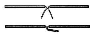 |
| Figure 1. |
A sleeve of pipe a little longer than the cable pipe, and long enough to cover the proposed splice, and lap 3 or 4 inches over at each end, should now be slipped over one end, and when the conductors are all joined, and paraffined as we have described, the sleeve can be drawn forward over the splice and joined to the cable pipe by a wipe joint using fine solder.
TERMINAL CONNECTIONS AND LIGHTNING ARRESTERS.
It is very necessary where aerial cables are used, to provide a suitable connection at the outward end for the attachment of the cable conductors to the line wires, and at both ends to attach lightning arresters. We show one very good style of pole box, into which the cable is led intact. The wires are then fanned out to each side and separately terminate at binding screws, which are placed on a bar in a row. The pole line wires enter at each side, and are terminated in the same way. A metal bar extends on each side between the pole line, and cable line screws, and each pair of terminals is connected by a little piece of comparatively fine wire, which is twisted ojnce round the interposed metal bar. The metal bars being connected with the ground, serve as lightning arresters, and the short pieces are easily renewed.
| |||
| Figure 2. |
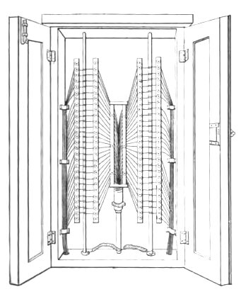
Where aerial cables run near electric light wires, fusible links, such as narrow strips of tinfoil should, in addition to the lightning arresters, be placed in the line circuit, as electric light currents with a much lower electromotive force than lightning, have great heating power, and would soon destroy a telephone cable.
TESTING INSULATED CONDUCTORS IN CABLES BY MAGNETO
BELL.
We have known many persons who were in the habit of testing cable conductors for insulation by ringing a magneto-bell into it, the conductor meanwhile being open at the distant end. As a matter of fact which should be well known, a magneto-generator sending alternating currents will ring its own bell as well on an open as on a closed wire, if the insulation is what it ought to be; and for this purpose a magneto-bell though almost too handy should not be used. If the insulation is good, the first pulsation sent by the generator may not be sufficient to move the armature, but the second being of opposite direction, having not only to charge the wire but first to neutralize the charge already there, may be strong enough, and the bell rings. On the contrary, if the insulation is not up to the mark, the first charge leaks out before the second comes in and the bell does not ring, except in case the insulation is very low indeed, and then it rings on the escape.
A 50-cell chloride of silver battery, and a magnetotelephone serve to test a cable very well, if the insulation is normally high. Grounding one pole of the battery, we connect the other pole to one of the telephone terminals, and a wire to the other telephone terminal. Now, if we touch the free wire, to the end of the cable wire, if the said wire is perfectly insulated, we hear a click, the loudness of which depends on the length of the wire. This click arises from the rush of electricity through the telephone to charge the cable. Now, if the wire be touched a second time no click will be heard because the wire is charged. If the insulation is deteriorating the charge will leak out before the second touch, so that a very perceptible click will be heard the second time. This test, of course, only tells whether the insulation is or is not falling; but if that is once ascertained, the insulation resistance can then be measured. In testing for a break in the same manner, a little experience soon enables one to tell from the sound of the click, the approximate location of the break.
In addition to aerial cables, the constructor is frequently called upon to use office cables. These are usually cables consisting of any required number of wires insulated to a greater or less degree, and covered ordinarily with a cotton braid. If a more ornamental appearance is desired, a silk covering is added. The purpose of these cables is merely a concentration of conductors, so as to economize space, and no special mention of them at this time seems to be required. It will be necessary to refer again, hereafter, to aerial cables when the several methods of suspension will be described.
Before leaving the subject of line wire, it may be mentioned that a line of copper wire built November, 1877, was taken down in August, 1884, and was found to be scarcely diminished in size, and in no way oxidized. This wire was drawn to a degree of hardness which would admit of the regular telegraph twist joint. The line in question was built at Ansonia, Conn., and demonstrates beyond a doubt that hard copper wire (for short lines at all events) will "stand up," that it does not stretch unduly, and that it is not affected in an equal degree with iron, by atmospheric or gaseous agencies.
(To be continued.)
