[Trade Journal]
Publication: The Electrician & Electrical Engineer
New York, NY, United States
vol. 6, no. 5, p. 178-182, col. 2,1-2
ELECTRICAL TRANSMISSION OF POWER BY
BROWN'S DYNAMOS.¹
WHILST steady progress is being made in almost every branch of electricity, the theory developed and the instruments perfected, the most interesting question, the electrical transmission of power, which first roused the enthusiasm of the scientific and unscientific, seems to remain a pium desiderium. The Niagara Falls still waste their energy instead of enlightening and benefiting the whole State of New York and the adjoining districts of Canada; and the waves continue to gnaw at the British Isles without giving any return by supplying the lighthouses with the necessary light currents. A few isolated cases are known where electricity affords the satisfactory means of utilizing at a distance the power which is cheap but useless at one particular spot; but we hear nothing of permanent installations on a large scale. At the Vienna exhibition of 1873, a gas motor was made to drive an electric machine whose current was sent to another electric machine which actuated a little centrifugal pump; that was an experiment. Such experiments were repeated at the exhibitions at Philadelphia, Paris, London, Munich, and again at Vienna, everywhere exciting the most lively interest. At Munich, M. Marcel Deprez made a very decided and promising step forward; his continued tests between Paris and Creil, a distance of 35 miles, followed; but a long time passed before any definite results were published, and it required the munificence of Baron Rothschild to render the tests possible. The uncertainty about the results had shaken confidence, and when it became known finally that the commercial efficiency had not risen above 46 per cent., many a practical engineer returned to his old opinion that, after all, the transport of coal was cheaper than the transport of power in any form.
Under these circumstances all further experience is most welcome. We are to-day enabled, through the courtesy of Mr. C. E. L. Brown, of the Tool and Engine Works at Oerlikon, near Zurich, to place before our readers the results of some tests on the electrical transmission of power, made with Mr. Brown's new dynamos and motors. The tests were conducted by the maker in conjunction with independent and competent experts, Professors Amsler-Laffon, Gysel, Veith and Weber, and Messrs. Keller, Lang, Meier, Naville, Waldner, and Zschokke; the report was compiled by Prof. Amsler-Laffon. The machines were constructed for the transmission of a water power of about 50 horse from Kriegstetten over a distance of 8 kilometers (five miles) to the works of Mr. Mueller-Kaiber at Solothurn, in Switzerland. The tests were made in the works of Mr. Brown, on conditions as nearly as possible equal to those to be fulfilled later on; their object was a practical one; to answer the questions: What power must be supplied to the primary machines, so that the secondary machines can do a certain work? What relations exist between the speed of the primary and of the secondary machines? How does the speed vary with varying work? Electrical instruments were used only so far as electrical magnitudes were directly concerned; the power measurements were taken mechanically. We will conclude these introductory remarks by adding that a commercial efficiency of over 70 per cent, was obtained.
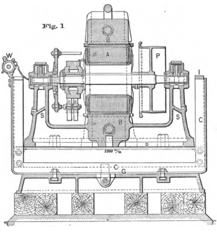 |
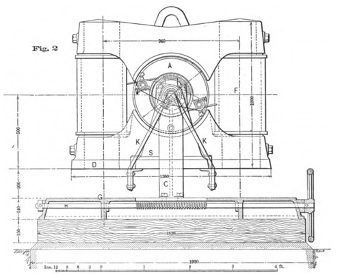
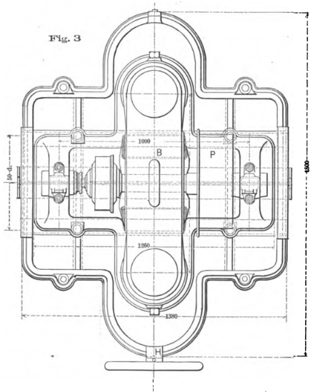
The general design of the dynamos will be understood from diagrams; figure 1, a longitudinal section, figure 2, an end elevation, and figure 3, the plan, showing the construction. Two vertical pillars, F, of wrought-iron form the field magnets; they are united by cast-iron blocks, B, acting as pole pieces. The lower block B, the bed-plate D, and the supports S, for the armature A, are cast in one piece. The armature of the motor is a modified Pacinotti-Gramme ring. We are not in a position to give a detailed description of the peculiarities of this armature; but it appears clear that the remarkable efficiency of Mr. Brown's dynamo must be ascribed to the ingenious though simple alterations which he has made in the armature and its relative position to the field magnets. The shaft bears the armature on the one end, and the pulley P on the other, that is, within the bearings. One of the first dynamos embodying these improvements gave at a speed of 1,000 revolutions per minute a difference of potential at the terminals of 65 volts and a current of 160 amperes; the armature wire weighed 12 kilogrammes (26 lb.) with a resistance of 0.008 ohm; the field magnet coils weighed 33 kg. (73 lb.), and had a resistance of 25 ohms. The newer dynamos for the Solothurn installation are of a larger type, and give about 1,200 volts each, with the normal speed of 700 revolutions per minute. Their principle dimensions are: Total length, 4 ft. 1 in.; width, 4 ft. 5 in.; height, 3 ft. 3 in.; diameter of armature, 20 in.; length of armature, 12 in.; and diamter of pulley, 20 in.; width, 7 in.
 |
As reliability is the first requirement, Mr. Brown decided to use four machines, two generators and two motors, so that in cases of emergency one pair alone could take the main part of the work; the water-power to be transmitted varies between 30 and 50 h. p. A speed of 700 revolutions was selected, both as being economical and not too high; a lower speed would have required heavier and more expensive dynamos. The three lead system has been adopted, all three wires being naked pure copper wires of six millimeters (1/4 in. in diameter) suspended on poles about 190 feet distant from one another with fluid insulators; the river Aare is crossed by one span of 380 feet length of a silicium bronze wire, having about the same thickness and equal conductivity as the copper wire, but possessing at least double the tensile strength. With the two generators in series an electromotive force of 2,500 volts is obtained. The three wire system offers the advantage that should one of the motors stop, the other would never receive more than one-half of the total tension; an arrangement has further been made by means of which one of the outer wires can be connected parallel with the central wire, in case one of the generators should have to work alone; thus the loss in the conductors would not be doubled, but increased by one-half only. The primary station comprises besides the two generators two automatic shunts short circuiting the field magnets in case the currents should become dangerously strong two ampere meters and further, three lightning conductors with lightning plates of an original kind for the protection of the dynamos against lightning. The secondary station is equally protected; it contains further two fluid cut outs permitting of stopping the two motors suddenly without endangering the insulation.
 |
The contract required a constant speed independent of the work to be done as a main condition. Constant speed may be secured mechanically or electrically. Electrically this regulation may be effected by various methods, three of which command particular consideration. The first method uses a primary dynamo (generator) of the compound type, and a simple shunt motor for the secondary station; this arrangement recommends itself for medium tension currents. The second method has compound wound machines for both the primary and the secondary stations; the object of the series wire being in the first case to supply a higher tension for a greater load, and in the second case to weaken the magnetic field of the motor proportionally; this arrangement offers advantages when one generator has to feed several motors. The third method takes series dynamos for both stations, and as it is particularly adapted for high tensions, and when one primary station has to supply one secondary, it was selected here as we mentioned already; it further admits of easy starting, even with a full load. With properly designed and constructed dynamos this arrangement ought to turn the motors with a constant speed, provided that the generator rotates at a uniform rate. Mr. Brown finds that when varying the brake power applied up to 20 per cent, the speed of the motor did not vary by more than three per cent. These slight variations might further be reduced if it should become necessary.
We come now to the test at the Oerlikon works, carried out under the actual conditions under which the dynamos will have to work, the line wire of 9.5 ohms resistance being replaced by an iron resistance of 10 ohms. This iron wire was shortened in proportion to its becoming heated through the current whose strength was controlled by means of a voltameter; thus the resistance was kept constant. Being aware of the diffidence with which the practical engineer regards electrical power tests, in which he has to trust electrical instruments of whose reliability he cannot convince himself by experiments of his own, Mr. Brown decided in favor of mechanical power tests. All the four dynamo machines were suspended in cradles, C, bolted to a baseplate, G, which was provided with a screw spindle, H, for the adjustment of the belts. The vertical limbs of the cradles end in knife edges, I; and on these the whole dynamos rested, being held by an iron strap, K, which strap was firmly bolted to the dynamo bed-plate, D. The edges, J, were placed exactly in the prolongation of the armature shafts. Pointers of 6 ft. length were attached to the field magnets; and the power applied, or required, calculated from the deflections from the vertical line which the generators suffered under the pull of the belts from the steam engines, and the motors under the influence of the currents transmitted from the generators. The speeds were indicated on a counter connected with the armature spindles by a flexible shafting and a worm gearing, W. This method of estimation necessitated preliminary trials to ascertain directly by weights applied to the pulley P, the power corresponding to the different positions of the pointer. For this purpose the armature was rigidly fastened to the field magnets during these trials; thus a power scale was obtained, indicating in kilogrammes the weights which acting on a lever arm of 0.25 metre (9.8 in.) the common radius of all the pulleys, P produced the respective deflections.
The total resistance of the four dynamos connected in series that is, the two generators in series connected in series with the two motors, also in series amounted to 13.44 ohms; adding to this 10 ohms for line resistance, we get the total resistance of the system equal to 23.44 ohms. The belts having been put on the primary dynamos the motors were coupled to a light machine whose circuit resistance was increased by adding arc lamps. When the generators made about 100 revolutions per minute, the motor armatures began to spin; the deflections of the pointers soon become stationary. All corresponding observations were taken within the space of one minute.
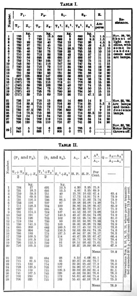
The tests were made on five days in November, 1886; the principal tests, which we summarize, on November 22d and 29th. Table i. gives first the results of the tests of November 29th. The columns P1, and P2 refer to two primary machines, S1, and S2 to the secondary machines; those marked T state the speeds, Z the deflections of the generators; the same letters with dashes apply to the motors; column E gives the current strength in amperes. The deflections under Z are given in kilogrammes, as has already been explained. The speed counter for P1, failed after 14 observations had been taken. The figures in parentheses were only estimated. The lower part of table i. relates to the tests of November 22d ; two further tests of November 30th are subjoined. Table ii. refers to the same tests, giving the corrected values after elimination of possible errors. The suspension of the dynamos proved very delicate and satisfactory. There was, however, magnetic attraction between the dynamos and the groundplate G, the distance from the bed-plate D to G being only about 1/2 ft. It was ascertained that this magnetic attraction would lead to too low readings when the pointer was near zero, but would be without influence when the pointer was near 40; and would cause too high readings after that. This was determined by passing electric currents through the field magnets and forcing the pointer gradually over the scale by loading the machine, regulating the currents to the strength which the tests (table i.) had shown to correspond to the respective position of the pointer. The error is very slight, and attains practical importance only for the readings above 80, when reductions have been made, 1/2 kg. for 80 kg. to 90 kg., 1 kg. for 90 kg. to 100 kg., 2 kg. for 100 kg. to 110 kg., 3 kg. for 110 kg. to 115 kg., and 4 kg. for 115 kg. to 120 kg. The belts might further tend to shift the cups of the strap K, slightly on the knife edges J, and since the pointer scale was determined when the belts were off, these errors would only appear whilst the dynamos were at work, and not during the preliminary trials. This error, again, could only be insignificant, as the radius of curvature at the cups was very small. Yet this shifting had actually occurred in the case of the generator P2, for its pointer did not go back to zero when the machines were stopped, but stood at 2 1/2 kg. Similarly, the motor S1 had been shifted a little, of course in the opposite sense its pointer pointing to 1 kg.
The whole method has carefully been analyzed by Prof. Amsler-Laffon. The position of the pointer will depend upon the electrical reaction between the armature and the field magnets; the friction in the bearings, and the resistance which the moving armature and pulleys encounter from the air. We have further unavoidable losses of power within the dynamos, and the mechanical defects which would accompany any mode of suspension. As we have just mentioned, the belts might be expected to pull the dynamos slightly out of their central line, shifting them horizontally; a slight deviation from the central axis might also occur in the vertical plane; and lastly, we have the magnetic attraction between the dynamos and the ground plate G, already alluded to. Prof. Amsler convinced himself that these sources of error could not materially affect the results. That this opinion is justified, he proves by determining the efficiencies first, directly from the figures observed, by dividing the power A1, imparted to the generators into the power A2, yielded by the motors, this calculation giving the column A2/A1, or efficiency in per cent; and secondly, by subtracting from the powers absorbed or reproduced respectively the powers corresponding to the minimum loads, and thereby eliminating those possible errors which cannot be controlled experimentally, but which would be the same for higher and smaller loads. A2º, and A1º, represent the powers received or expended in each particular case, A2º, and A1º, the same for minimum loads derived from the means of experiments No. 1 and No. 2, table ii., thus A2º, = 3.25; A1º, = 4.48; if we then form the quotient of the differences A2-A2º/A1-A1º = Q, we arrive at the commercial efficiencies by a method independent from the sources of error which influenced the figures in column A2/A1, It will be seen that there is a most satisfactory agreement in the commercial efficiencies as determined by these two methods; those under Q are, of course, the more reliable figures.
 |
Prof. Amsler-Laffon adds a few recommendatory remarks to his report. The Brown dynamos are distinguished by a simple, solid, and judicious construction; the brushes are easily accessible, showed very little sparking, and did not require and adjustment during the tests when more and more lamps were added; there would thus be very little wear to both brushes and collectors. The field magnets became only slightly warmer during a run of several hours. The speed 700 revolutions per minute Prof. Amsler regards as rather high. Since, however, the speed of motors remained practically constant during the trials increasing a little with augmented resistance in the exterior circuit and deviated little from the speed of the generator, provided the latter was driven at a uniform rate, it appears hardly advisable to try to reduce the speed for the sake of questionable improvements. Prof. Amsler acknowledges further the excellent provision by means of automatic short circuiting devices against too strong currents; and finally dwells upon the remarkably high efficiency realized, which is scarcely likely to be surpassed.
We must bear in mind that the percentages indicate commercial efficiencies, as they represent the ratio of power yielded to power expended, both measured mechanically. The performances of electric machines have been calculated in so many different manners, that it may not be superfluous to set this point clear. The tests of November 29, yielded a mean efficiency of over 70 per cent.; Mr. Brown's previous tests of November 29, gave a mean of 76.9 per cent. This difference requires an explanation; and the reason is pretty apparent. On November 22, both primary generators worked with approximately equal power, hence the differential current in the central wire of the three wire connection was almost zero, and the loss of energy consequently a minimum. On November 29, however, these powers differed very considerably, in some cases by even more than 100 per cent.; a glance at the columns Z1 and Z2, of table i. will establish this; table ii. gives the means, and therefore does not permit any conclusions as to the different working conditions. Heavier currents could not but result under these circumstances; hence the lower efficiency. We have above referred to M. Marcel Deprez's experiments and their maximum mechanical yield of 44.8 per cent. Of course, M. Deprez's line was much longer and had a resistance ten times as great, nearly 100 ohms. As his current was 9.8 amperes, his line absorbed almost 13 h. p. out of the 86 indicated by the dynamometer at the generator; M. Deprez had only one generator, a powerful Gramme dynamo giving a current of 6,000 volts. It will be interesting to mention for comparison the experiments on the electrical transmission of power by M. Hippolyte Fontaine, the results of which were, like those of M. Deprez, presented to the Paris Academic and published in the Comptes Rendus. The data of the two tests were almost the same, M. Fontaine also transmitting his currents of 6,000 volts and 9.34 amperes over a line of 100 ohms resistance; but M. Fontaine's experiments resemble more those of Mr. Brown in one respect, as M. Fontaine had four dynamos in series as generators and three in series as motors, similar to the two generators in series and the two motors in series of Mr. Brown. In M. Fontaine's line almost 12 h. p. were lost out of 96 h. p. supplied to the generator; his industrial yield was 52 per cent. If we make the same calculation with regard to the power absorbed by the line in Mr. Brown's tests, we find (in No. 14) with a current of 15 amperes and a line of 10 ohms resistance, a loss of about 3 h. p. against 62 h. p. measured at the generators. But it would, of course, be incorrect to deduct 13 per cent., which were expended in overcoming the resistance of M. Fontaine's line, for the Oerlikon case, and to calculate thus an efficiency of over 64 per cent, for the Brown dynamo when working over a line of M. Fontaine's length, since the whole conditions would be altered, and since the dynamos were not constructed for a line of 100 ohms resistance. But the comparison speaks very favorably for Mr. Brown's dynamos, particularly if we consider that the tests, when the power transmitted exceeded 30 h. p., that is, when they corresponded to the actual conditions for which the plant was designed tests Nos. 9, 10, 14, 16 demonstrated a mean efficiency of 73.9 per cent. These are the experiments which were alluded to during the recent discussion of Mr. Sturgeon's paper before the Liverpool Engineering Society.
1. From Engineering, London, March 11.
