[Trade Journal]
Publication: The Electrician
London, England
vol. 60, no. 1547, p. 472-476, col. 1-2
THE WAIPORI HYDRO-ELECTRIC POWER TRANSMISSION SCHEME
BY W. G. T. GOODMAN.
(Continued from page 438.)
Summary.The author describes the hydro-electric installation which has been put down to supply power to the municipality sf Dunedin, in New Zealand. Water for operating the Pelton wheels installed in the generating station is obtained from the Waipori river under an effective head of 665 ft. The three-phase alternators generate current at 2,100 volts; this is transformed to 35,000 volts for transmission purposes. Some interesting constructional work is described in connection with the transmission line, the distance from the power station to Dunedin being about 30 miles.
TRANSMISSION LINE.
It will be noticed from the diagram, Fig. 5, that, after leaving the power station, the high-tension transmission lines proceed for a distance of 21 miles to sub-station No. 2. This substation is located on the Taieri plains in order to meet the conditions demanded by the, Taieri County Council for granting the right to the Dunedin Council to take the transmission lines along the roads within the Taieri County. The nature of the agreement is that, as soon as the Dunedin Council have contracted for a demand that will take four-fifths of the capacity of the installation, the remaining fifth may be utilised for the benefit of the residents of the Taieri County at a rate not exceeding that given to the most favoured consumer in the City of Dunedin under like conditions of supply. In this sub-station it will be seen that the connections are so arranged that the transmission lines may be interconnected in any manner. There will also be a bank of transformers for reducing the pressure to 3,300 volts for use in the neighbourhood. About 1 1/2 miles from this sub-station is the town of Mosgiel, where there is a large woollen factory and several mills, which eventually will, no doubt, be connected to the system.
After careful consideration, a voltage of 35,000 was adopted as being reasonable for insulation and economical as regards weight of copper in the line. The total distance along the transmission route from power station to sub station No. 1 is 27 miles H chains, and from the sub-station to the converter station, in the centre of Dunedin, 2 miles, the total length of transmission being, therefore, 29 miles 8 chains. The Council adopted the writer's recommendation that the transmission line should be in duplicate throughout, and the lines entirely independent of each other.
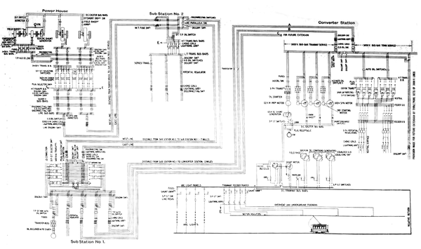 |
| Fig. 5.Diagram Showing General Arrangement of Transmission. |
The site of the power station is 436 ft. above sea-level, and the hills forming the banks of the river have an angular slope ranging from 30 deg. to almost vertical. These hills are covered with dense bush to about 1,000 ft. above Bea level, and as it would have been a very expensive matter to construct the transmission line on the slopes of the hills, the route chosen was across the top of the divide between the power station and the Taieri plains. On the opposite bank of the river to the power station there is a small plateau, and then the hill rises with an average angle of about 40 deg. to a height of 1,095 ft. above the sea level, and thence the country gradually rises to an elevation of 2,000 ft. above sea level. At this altitude there is a fairly level tableland, which is about two miles across, and then the mountain, which is known as Maungatua, slopes towards the Taeiri plains with a series of sharp spurs. The country on the top of the mountain is entirely open, and mostly used for grazing purposes. In winter it is exposed to the severe south-westerly winds and covered for days with snow. This route was chosen as being the most direct to the Taieri plains, and at the same time because of the ease of construction for the line and facility of patrolling.
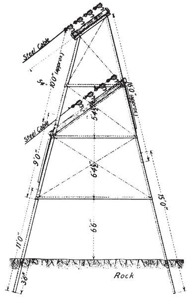 |
| Fig. 6.Side View of Top Tower. |
The transmission lines leave the power station at the top of the lightning arrester annexe, the wires passing through fibre tubes held in glass shields. From this point the wires are taken to a terminal tower on a spur about 80 ft. above and at the back of the power station. From this tower the wires are taken right across the ravine to a steel tower located on the top of the first bluff on the opposite side. It was decided that the line should be taken across in one span in preference to erecting poles at short intervals down the rugged face of the mountain side. This span is 1,700 ft. in length, and the horizontal distance between the towers about 1,000ft., the upper tower being 650 ft. above the terminal tower.
An experimental span of steel cable was strung up in approximately its permanent position, and the stress measured by a dynamometer was found to be 900 lb., when the initial angle of sag was 54 deg. from the vertical at the upper end, and 85 deg. from the vertical at the lower end. It will be seen, therefore, that this span is not quite half of a natural catenary. The steel cables used for this span have a tensile strength of 6,0001b., and are of sufficient size to carry 10 times the line current without heating.
| |||
| Fig. 7.View of Top Tower. |
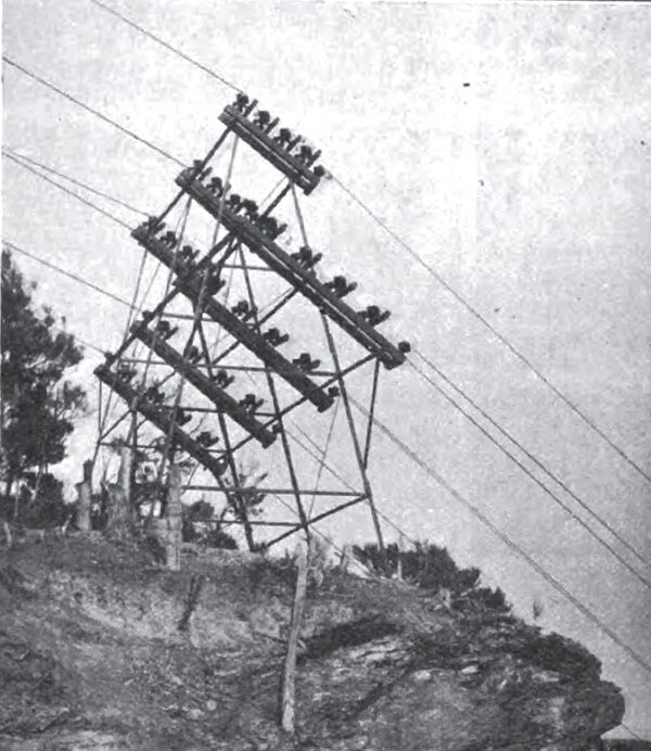
The tower at the upper end, which is shown in Figs. 6 and 7, is constructed of angle steel throughout, and with the insulators so arranged as to take the angular pull of the long span cable. This tower was a special piece of work calculated to withstand the stress of the seven cables. The stress of each wire is taken up, as shown in Fig. 6, by four pairs of insulators. Around the neck of each insulator is a " U" bolt, the ends of which pass through a wooden cross bar. The wire passes through a bole in the centre of the cross-bar, and iron clamps are clamped rigidly to the wire and rest against the upper side of the cross-bar. By this means it can be seen that the stress on each pair of insulators can be equalised by means of the nuts on the "U" bolts. Two pairs of insulators are sufficient to take care of the stress of the wire, so that ample margin of safety is provided. Seven wires are suspended across the span, three for each transmission line and one spare cable for use should any of those in service carry away. This provision was necessary, as, owing to the nature of the country at this point, it would be a most difficult matter to repair a span. Four of the wires arc of steel and three of No. 2 B. & S. gauge copper, and the latter appear to be as satisfactory as the former, except, of course, tint there is not the same factor of safety.
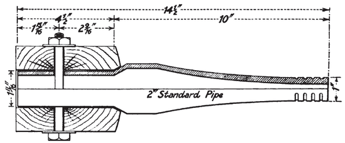 |
| Fig. 8.Cross-Arm Pin. |
The tower is erected on solid rock, and the cables have a minimum clearance of 10 ft. from the face of the hillside. The spans are not affected by the wind, which blows with great velocity at times through the gorge. They are spaced 10ft. apart triangularly, and each cable is drawn to the same tension. The lower terminal tower is made entirely of wood, consisting of six hardwood poles. This tower is anchored by guys, so that the only work it does is to hold the cables off the ground; the same methods of attaching the wires to the insulators was adopted as on the hill-top tower.
After leaving the hill-top tower, the transmission wires are carried on Australian hardwood poles, those used on the mountain top being 30 ft. in length with 6 ft. in the ground The question of towers versus wood poles was carefully considered, but as the Taieri Council would not agree (and rightly so) to towers being erected along their roads, there was no alternative. The cost is slightly in favour of wooden pole construction. The insulators are spaced 42 in. apart triangularly, the top insulator being attached to the top of the pole. The bottom insulators are carried on ironbark cross-arms gained and bolted to the poles by two lag screws. The gains were cut slightly slanting, so as not to provide a pocket for moisture. Fig. 8 shows a cross arm pin. The cross-arms are 4 ft. 6 in. long by 4 in. by 5in. The poles arc spaced 150ft. apart, and the two lines of poles are 30 ft. apart over the mountain top.
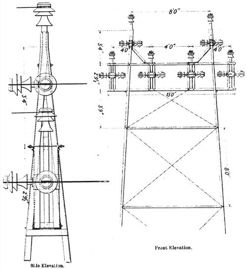 |
| Fig. 9.Steel Tower for Outram Railway Crossing. |
The transmission wire is of two sizes, No. 2 B. & S. gauge, and No. 8 B. & S. gauge, and is of medium hard-drawn copper, with a tensile strength of 50,000 lb. per square inch. The reason of two sizes of transmission wire being used was on account of the Council having purchased, some years previously, 72 miles of No. 2 B. & S. gauge for the Lee Stream scheme. This wire was sent out on reels, and was used on that portion of the transmission line on the plains. The remainder of the wire was purchased later, and is No. 3 B. & S. gauge, and was sent out in bundles for ease of transport over the hills. There are 164 miles of copper wire in the transmission lines.
| |||
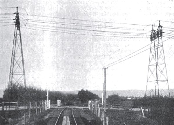
| Fig. 10.Outram Railway Crossing. |
| |||
| Fig. 11.Outram Railway Crossing. |
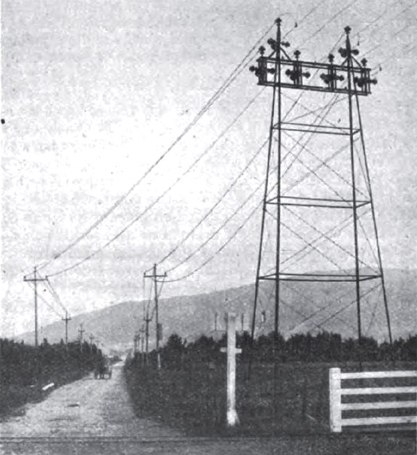
After leaving the tableland referred to, the route of the transmission line is along the ridge of the Kowhai Spur or Razorback, and in this case it was also necessary to keep the pole line on the top of I the ridge, as the sides are covered with dense bush. In a few places in crossing the tableland small creeks and depressions were crossed with spans ranging up to 300 ft. in length. Before reaching the bottom of the Kowhai Spur another long span had to be adopted in order to cross a small valley. This span is 900 ft. in length, and the wires are spread out to 6 ft. spacing, the two lines being supported on long double cross-arms on three poles at the upper end. The line then continues across private property until it strikes the main road on the plains, 7 miles from the power station. From this point the poles are erected along either side of the 'road, being located in the fence line, where the roads are 40 ft. wide and 6 ft. from the fence alignments, where the roads are 1 chain wide. The fine then continues on poles until it reaches the township of Outram, 14 1/2 miles from the power station. At this point towers had to be erected for crossing the railway. These towers were specially designed to meet the requirements of the railway department, who insisted on provision being made to prevent any possibility of a wire falling across the railway line, either due to breakage of insulator or wire. The type of tower is shown in Figs. 9, 10 and 11, from which it will be noted that the insulators are only subject to compression stress. Steel wires are used for the crossing with a tensile strength of 6,000 lb., and as the working stress is only 400 lb. the factor of safety is ample. It is impossible for any cable to fall from the tower if all the insulators break; the copper wires which terminate on the tower above the steel cables are connected to the latter by soldered clamps.
After leaving the Outram railway crossing the lines arc taken through private property, in order to cut off a long detour and to avoid going through the township of Outram. The line proceeds along the Outram-Mosgiel road and the north-west Taieri road until it reaches the site for sub-station No. 2, 21 miles from the power station. It then proceeds on steel towers across private property, in order to again avoid a long detour, crossing another line of railway, and proceeding thence along the north-west Taieri road to the Silver Stream river, 23 miles from the power station. From this point the route leaves the plains, and is taken 4 1/10 miles through private property, ascending at an average grade of 1 in 8 over a spur of Flagstaff Mountain rising to an altitude of 1,125 ft., and then descending until it reaches the sub-station at Half-way Bush, 645 ft. above sea level.
At the point where the route of the transmission line is taken through private property at Outram, and again after leaving substation No. 2, the lines are carried on steel towers because the property owners objected to a double line of poles running through their lands, as they held same would obstruct ploughing and farming operations. These towers are spaced 500 ft. to 600 ft. apart, and each tower carries the six transmission wires and telephone line. The towers are rectangular structures, the length of the base parallel to the line is one-fifth of the height, and the width is 14 ft. The towers vary from 40 ft to 50 ft. in height, according to the nature of the ground, and the angle steel sections are in 10 ft. lengths. The bracing stays consist of two No. 7 S.W.G. steel wires, twisted with Spanish windlass and with eccentric washers in the bolts to provide for adjustment of the strain. In the design of the line throughout a factor of safety of six was adhered to in all calculations; this factor was insisted upon by the Board of Control as being sufficient to provide a safe margin against all snow and wind stresses.
The linesmen were provided with adjustable sighting pieces, which were hung at each pole and the cable strained with a sag to correspond with the length of span and temperature of the atmosphere. The wires were tied to the insulator with No. 8 soft-drawn copper, and all joints made with Mclntyre's figure 8 tubes. No ladders were used in the erection of the line, as the men climbed the poles with spurs, two types of which were used. Neither of the high-tension lines are transposed throughout the length.
One of the Government telephone lines runs parallel to the transmission line for a length of 2 miles, and at a distance of 20 chains from the line, and no trouble was experienced due to induction, only a very slight humming being perceptible.
The insulators and pins were delivered along the line of route and deposited at the foot of the poles. At first the pins were fixed in with litharge and glycerine cement, as this is quick setting, but as the men complained it made their fingers very sore, and it was found the public did not damage the insulators, the litharge and glycerine was substituted with Portland cement, mixed one part to one part sand, and the pins were allowed to stand four days to set. The pins are of ordinary 2 in. galvanised iron pipe swaged in. Iron pins were adopted because the writer thought if wooden pins were used there would probably be trouble, owing to the very moist climate conditions which prevail during a great portion of the year. The pins were made by the Johns, Manville Co., and the insulators by R. W. Thomas & Sons, New York. The insulators were made of brown porcelain throughout, so as not to provide a good mark for boys with pea rifles.
(To be continued)
* Abstract of a Paper read before the Electrical Association of New South Wales.
