[Trade Journal]
Publication: The Electrician
London, England
vol. 60, no. 1548, p. 510-513, col. 1-2
THE WAIPORI HYDRO-ELECTRIC POWER TRANSMISSION SCHEME.
BY W. G. T. GOODMAN.
(Concluded from page 476.)
Summary.The author describes the hydro-electric installation which has been put down to supply power to the municipality of Dunedin, in New Zealand. Water for operating the Pelton wheels installed in the generating station is obtained from the Waipori river under an effective head of 666 ft. The three-phase alternators generate current at 2,400 volts; this is transformed to 35,000 volts for transmission purposes. Some interesting constructional work is described in connection with the transmission line, the distance from the power station to Dunedin being about 30 miles.
TRANSMISSION LINE (continued)
The specification for the insulators was very drastic. The porcelain had to be thoroughly vitrified and absolutely non-absorbent of moisture, and stand the voltage test without the surface glazing. Half of 1 per cent, of the insulators were subjected to the following tests: The porcelain was broken into small pieces and kept in a dry place at a temperature of 212°F. for 12 hours and then accurately weighed. The pieces were then soaked in water for 24 hours and carefully wiped, after which they were again weighed and the porcelain rejected if the weight was different to that before soaking. No insulators were accepted that showed any mechanical weakness before or after glazing. As a mechanical test the insulator was mounted on an iron pin, and a pull of 2,50O lb. exerted on the tie wire groove and parallel to same.
For the wet arcing test the insulator was mounted on an iron pin set in a metal cross arm 4 in. wide and projecting 12in. beyond the pin on either side. At right angles to the cross-arm a No. 3 B. & S. wire, 3 ft. long, was tied to the insulator, and the voltage applied between the copper wire and the cross-arm. A spray of water sufficient to cover the insulator was then allowed to play on same from a sprinkler, under pressure of 50 lb. per square inch at the nozzle, placed at an angle of 80 deg. from the horizontal and not over 4 ft. from the insulator. Under these conditions the insulator must not arc from the wire to either pin or cross-arm at a less potential than 40,000 volts effective E.M.F., the tests lasting for one minute after reaching that voltage.
For breakdown test the insulators were placed inverted in a brine solution in a metal tank for a depth of 1 in. below the head. The pin hole was filled with brine and a metal rod placed therein. After the insulator had stood in the brine for one hour it had to stand an effective E.M.F. of 70,000 volts, applied between the metal rod and the metal tank, without either arcing across or puncturing or showing any sign of electrical weakness.
In the line there are 1,802 poles and IS steel towers. All poles and towers are numbered with enamelled iron plates, and on every alternate pole there is a notice on enamelled iron offering £5 reward for information leading to the conviction of any person found damaging the lines or insulators.
At all road crossings there are 45 ft. poles with double cross-arms and insulators, which are also used at all angles. The poles are mostly 35 ft. in length and rough dressed, the wood being either blue gum, Hooded gum, tallow wood, black butt or turpentine, and cost on an average £2. 5s. each, erected. All poles are ringed at the top.
There are two linesmen whose duty it is to patrol the line daily. They both reside at Outram and are provided with horses, one man proceeding over the 17 1/2 miles of line to the power station one day, staying there for the night and returning to Outram the next day. The other linesman patrols the 9.6 miles of line from Outram to Half-way Bush, returning to Outram every night. The linesman on this section hands in both linesmen's daily reports on every alternate day to the sub-station attendant, who forwards them to the bead office.
Each linesman has to call up and report to the power station and sub-station No. 1 at each telephone box along the line, stating the direction in which he is going. These calls are entered up in the log books. The linesman on the power station section has a very rough time during the winter months, as heavy snowstorms prevail, and the ascent and descent is very steep on both slopes of the mountain, so much so that many people prefer to walk instead of riding. The writer on several occasions has ridden through 2 ft. of snow when visiting the power station. During the month of June last there were several heavy falls of snow, but none adhered to the line wires and no line troubles arose from same.
The whole of the insulators were erected at the end of February, and up till the time that the writer relinquished control (May 18) of the undertaking no insulators had been reported broken; in fact, there had been no line troubles of any description. Since that date three insulators have been broken, but it was not necessary to renew them immediately. In the author's opinion so few breakages are extremely satisfactory, especially when it is borne in mind that 19 miles of the line is along public roads. It was found necessary to cut down no less than 1,400 trees along the line of route which endangered the safety of the line. With respect to the 10 miles of transmission line through private property, the writer was able to secure the sole right of ingress, egress, and regress at all times for the moderate figure of £600.
The efficiency test of the line confirmed the calculated loss. As previously mentioned, each line consists of 12 miles No. 2 B. & S. gauge, and 15.1 miles No. 8 B. & S. gauge. The calculated resistance is 26.23 ohms., and the measured resistance is 27.11 ohms. Taking 1,000 kw. at 30,000 volts with 90 per cent, power factor at the receiving station, the line current is 21.1 ampere, the calculated voltage drop, allowing for inductance and impedance, is 2,192 volts, and in the test made by the writer the measured voltage drop was 2,200. Each line is designed to carry 2,000 kw., with a loss of 8.75 per cent, at full load with 85 per cent, power factor.
A telephone line connects the power station to sub-station No. 1, and is carried on one line of poles on bracket insulators. It is a metallic circuit throughout, and the telephone wires are alternately 7 ft. 3 in. and 7 ft. 9 in. from the line wires. The wires are transposed vertically and across the pole every three pole-lengths, so that a complete helix is obtained in every 12 pole lengths. On the towers, as the spacing of the line wires is different from that on the poles and the interval between the towers is irregular, in order to keep the inductive effect on the telephone line to a minimum, instead of the bare copper, as used on the poles, two ordinary insulated telephone service wires were twisted together and strung from tower to tower. The twisted insulated wire was supported on steel suspension wire, carried on the insulators on the towers. The result of the transposition is that, with the full voltage and current on the main transmission line, the telephone circuit is almost quiescent.
The telephone wire is 12 B. & S. gauge hard-drawn copper, tied to the insulators by No. 12 B. & S. soft-drawn copper. The insulators were submitted to a wet arcing test with an E.M.F. of 4,500 volts and a puncture test with an E.M.F. of 8,000 volts, the tests made in a similar manner to those specified for the main-line insulators.
There are nine telephone stations along the line; these are arranged so that the linesman stands on a platform supported on four main-line insulators. The connections in the telephone boxes are made so that the linesman can talk to either end or both ends simultaneously. The telephone instruments are protected with long fuses and earthing device, so that, should the main line wire fall on the telephone at the time the linesman is using the instrument, it would be earthed and blow the fuse. This system was adopted by the writer as he did not deem it advisable for the linesman to carry portable telephones to connect the wires at any point, as it would be dangerous in the event of the line wire coming into contact with the telephone either accidentally or intentionally. At the power station and sub-station the telephone instruments are protected in a similar manner.
The sub-station at Half-way Bush is connected to the converter station by telephone wires running on the Government poles, as the Board of Control would not allow the main-line telephone to be taken right into town. In order to provide a duplicate means of connecting with the power station the writer installed another telephone line connecting the power station to the Government Telephone Bureau at Berwick.
SUB-STATION No. 1.
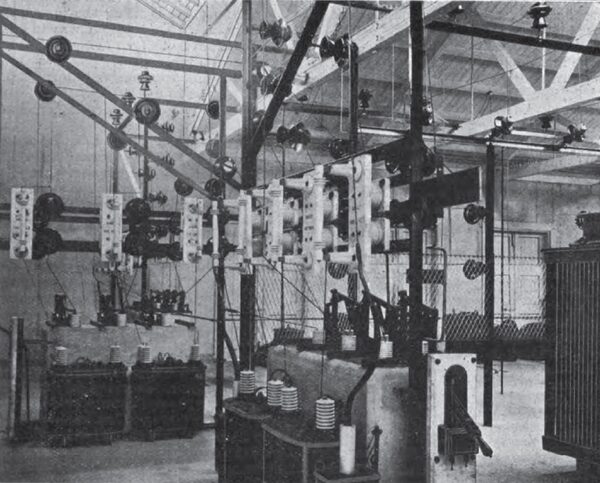
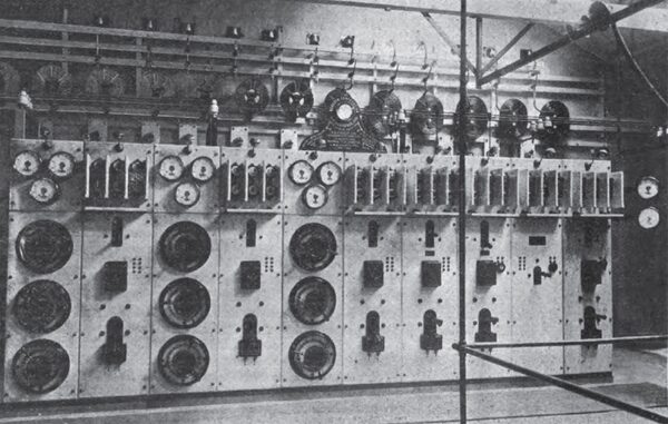
Sub-station No. 1, known as Half-way Bush, is designed to contain two banks of transformers of three each and one as a spare. Four transformers are installed of the Westinghouse oil-insulated, self-cooling type (Fig. 12), one being used as a spare. Each has a rated capacity of 600 kw., with a ratio of 18,000 to 3,300 volts. Taps are brought out on the high-tension side at 17,000 and 16,000 volt turns. The efficiency is 98 per cent, at full load, with 100 per cent, power factor, and 97 1/2 per cent, at 90 per cent, power factor The regulation is 1.1 per cent, at 100 per cent, power factor, and 2.9 per cent, at 90 per cent, power factor. The temperature rise does not exceed 40 C. after 24 hours' run at full load, and they are capable of carrying 25 per cent, overload for six hours after 24 hours' run at full load without temperature rise exceeding 55°0. The transformers are connected in "star" on the high-tension side and in "delta" on the low-tension side. As it was found necessary to take distributing mains from this sub-station, in order to provide easy regulation of the single-phase circuits, these mains are connected in "star," and the writer provided an artificial neutral by means of a No. 2 B. & S. gauge bare copper wire carried on the top of the low-tension transmission line poles from the sub-station and connected to the neutral point of the synchronous motors in the converter station. The system of wiring in the sub-station is similar to that adopted at the power station. The low-tension leads are connected by clamps to the 3,300 volt bus bars, which are overhead and run to the low-tension switchboard (Fig. 13), which was supplied by the Westinghouse Co. and is 20 ft. long; there are three panels controlling the low-tension transmission lines to Dunedin. On each panel there is an automatic oil switch with time limit relay and one double-throw oil switch, by means of which the outgoing line may be connected to either bank of transformers. There is a voltmeter receptacle and six knife disconnecting switches, for the purpose of isolating the oil switches; three of these are on the front of each panel, and three on the back. There is also a one-line paralleling panel, on which there are six disconnecting switches and one hand-operated oil switch for paralleling the low-tension bus bars. Provision has also been made for three local circuits to be taken from the sub-station; each circuit is controlled by two panels, on which are mounted six disconnecting switches, one automatic oil switch with time-limit relay, one double-throw oil switch, one voltmeter receptacle, three ammeters, one on each leg, and three potential regulators, by means of which the line potential can be varied 10 per cent, either way. At the back of the switchboard there are choke coils and Westinghouse lightning arresters on each line. The building is 68 ft. by 30 ft. by 10 ft. high, constructed of wood and galvanised iron, with concrete floor and lined inside with fibrous plaster on expanded metal. An air duct runs under each bank of transformers by means of which air is forced from a blower and can be impinged on the transformer cases to facilitate cooling.
The low-tension transmission line leaves sub station No. 1 and conveys the energy to the converter station in Dunedin. The line is in duplicate and carried overhead for 1 1/2 miles, and then underground for 1/2 mile through the busy part of the city. The overhead cables are 0.2 sq. in. triple-braided waterproof insulation. The six cables are carried on one cross-arm and are spaced 12 in. apart, and both lines are transposed twice in the length. The poles are dressed hardwood, 35 ft. long, with 6 ft. in the ground, and located along the line of kerbing.
At the point where the line is taken underground a large chamber under the footpath contains choke coils and lightning arresters for the protection of the two underground cables, which are three-core paper-insulated and drawn into Doulton conduits laid under the footpaths. Each line is designed to carry 1,000 kw. A second cross-arm has been provided on each pole for extra lines when required.
CONVERTER STATION.
The converter station is located in Cumberland-street, Dunedin, and is practically in the centre of gravity of the tramway system, and also of the power and lighting system. From the station alternating current is distributed in and around the city for lighting and power purposes, and direct current for tramways and street arc lighting. The generator room is 28 ft. 6 in. by 77 ft., and contains the machinery and switchboards. Adjoining this room is the transformer fireproof chamber, 10 ft. by 52 ft.; to the right of the transformer room there are two battery rooms, one above the other, and each 23 ft. by 77 ft.
| |||
| Fig. 12.Interior of Sub-Station No. 1, Showing Arrangement of Instrument Transformers and 35,000-Volt Fuses. |
In the generator room there are three motor-generators, each unit consisting of one Westinghouse 440 H.P. 3,000 volt three-phase synchronous motor coupled to a 300 kw. 550 volt direct-current generator. The field of the motor and the armature of the generator are mounted on one shaft, which is extended at the motor end to carry the rotor of a 40 H.P. 400 volt induction starting motor. The connections are arranged on the switchboard so that the set may be started and synchronised from either the direct-current or alternating-current side. The synchronous motors are designed for ample regulation so as to work satisfactorily at any power factor from 80 per cent, leading to 80 per cent, lagging; the temperature rise after 24 hours' run at 80 per cent, leading power factor does not exceed 40C. The alternating-current part of the machine had to stand a breakdown test of 10,000 volts.
The direct-current generator is designed to deliver 15 per cent, overload at 550 volts when running as a shunt machine, and to maintain the voltage at 550 volts from no-load to 5 per cent, overload when running as a compound machine. It was first intended to install rotary converters as a translating device from alternating current to direct current, but, owing to the contemplated nature of the power load on the system, the writer decided to install motor generators, in order to get the advantage of leading power factor by the synchronous motors when required.
The switchboard in the converter station is located on three sides of the generator room, and its total length is 68 ft. On the side adjoining the transformer room the switchboard is 47 ft. 4 in. in length, and consists of three sections. Section A consists of five panels; one panel controls the incoming transmission line A from sub station No. 1. On this station there is an automatic oil switch, polyphase wattmeter, reverse-current relay, three ammeters, one in each leg, line power-factor meter, static earth detector, voltmeter receptacle, and on the swinging brackets attached to the side of the panel are synchroscope, voltmeter for line, voltmeter for synchronous motors, and direct-current voltmeter for exciter generator. The second panel is for controlling the exciter and motor, whilst the other three panels are for controlling the synchronous motors, and mounted on each are:Power-factor meter, alternating-current ammeter, direct-current ammeter for field circuit, rheostat, voltmeter receptacle, automatic oil switch for synchronous motor, held-discharge switch, starting switch for induction motor, and reverse-current relay for synchronous motor.
The next section, switchboard B, is for controlling the low-tension distributing circuits to the low-pressure area in the centre of the city. This is arranged on the three-phase four-wire system, with 230 volts between each phase and the neutral.
Switchboard C, which is located at the end of the generator room, consists of four panels for controlling the 3,000-volt distributors. On each of these panels there are three potential regulators, automatic oil switch, three ammeters, one in each leg, and voltmeter receptacles for reading the voltage on each phase. The connections between the hand regulators and regulating transformers are taken overhead, and the latter are located in the transformer room.
At the end of switchboard A are the direct-current tramway panels, which consist of three generator panels, summation panel, battery-booster panel, three double-circuit feeder panels and one Board of Trade panel, mounted with the usual instruments. There are also two arc-lighting panels, which control six circuits of street lamps, there being 60 enclosed 6 ampere Angold lamps erected on top of the tramway poles.
| |||
| Fig. 13.3,000-Volt Switchboard in Sub-Station No. 1. |
On the opposite side of the generator room is the switchboard for controlling the three steam generators. During the last oh years the tramways have been operated from the steam power station adjoining the converter station. The plant consists of three 200 kw. Westinghouse generators, coupled to BellisB engines, and will be kept for service as a stand-by or auxiliary when required.
At the other end of the generator room there is the exciter for the synchronous motor fields, which is a 20 kw., 125 direct-current generator, connected to a 400 volt induction motor. A special motor-generator has been installed, consisting of a direct-current 500 volt motor, coupled to a three-phase, 400 volt, 50 cycle generator. This unit is for the purpose of maintaining the electrical supply to the railway department in the event of a stoppage in the hydro electric scheme, the power for operating the motor being obtained from the steam power station adjoining. There is also a differential battery booster consisting of a 37.5 kw- generator coupled to a 50 H.P. direct-current motor.
In the transformer room at the rear of the switchboard are four 150 kw. Westinghouse oil-insulated water-cooled transformers (one being a spare), ratio 3,000/242 volts, connected in "delta" on primary and in " star " with neutral earthed on secondary. The high-tension side is wound to give 10 per cent, up or down, and has turns tapped for 3,300 and 2,700 volts. The high-tension 'bus-bars are run overhead and connect to the oil switches on the switchboard. The transformers are connected to water and oil service systems, and in the transformer room there are also 39 regulating and instrument transformers. In the lower battery room there is a 300 ampere buffer battery with 260 cells. The whole of the converter station equipment was supplied by the Westinghouse Co.
DISTRIBUTION.
The low-tension distributing network in the busy portion of the city is by means of underground Callender vulcanised bitumen cables, laid on the solid system in new form of cement conduits. The feeders to the networks are four-core cables. The four cores are of equal sectional area, the object being that in the event of any core feeding the outers becoming earthed, it could be exchanged with the core serving as neutral. The mains are laid along each side of the streets under the side-walks, and consist of four separate cables, the neutral being half the sectional area of the outers. These mains are also laid on the solid system, and service boxes are provided at every alternate building. The outlying portions of the city and suburbs contiguous to Dunedin have been partly supplied with overhead mains at 3,000 volts, with local transforming stations at points of distribution.
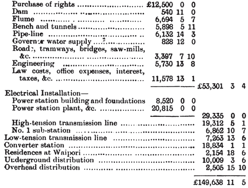
COST OF SCHEME.
The costs of the various works are given below. In reviewing the costs, it must be remembered that the work had to be carried out under most difficult conditions, and the cost of transport was exceedingly high, being from Dunedin £5 per ton. The stators for the generators, which weighed 10 tons gross, eaoh cost £60 for haulage from Lawrence railway station to the receiving shed, a distance of 26 miles, and 32 horses were required for each team; and they were four days doing the journey. Lawrence is 60 miles from Dunedin. The total value of electrical plant used in the installation is £24,251, of which £8,373 is General Electric and £15,878 Westinghouse. Hydraulic Installation
 |
Dunedin is the manufacturing centre of New Zealand, and in the vicinity there are large woollen mills, cement works, saw-mills, rope works, &c, and after a careful survey as to the probable demand for power and lighting the writer plotted out a series of curves.
From these it is seen that the estimated peak in winter-time occurs between the hours of 4 p.m. and 5 p.m. and is 1,380 kw., while in summer-time the peak occurs between the hours of 8 a.m. and 10 a.m. and is l,150kw. In a report by the author to the Council in June, 1900, recommending the scale of charges for electrical energy, the total cost of the scheme was estimated as £210,000, which amount included £75,003 for distribution. The operating expenses were estimated at £24,146 per annum, £6,829 being for salaries, wages, management expenses and maintenance, and £17,317 for capital charges, such as interest, depreciation, sinking fund, taxes, &c.
After careful consideration of the capital charges per unit sold per annum and the cost of generation and distribution per unit, the following rates were fixed: Lighting during ordinary hours, 5d. per unit lor the first 1J hours and afterwards Id. per unit. Special lighting rates during extraordinary hours, 4d. per unit for the first hour, afterwards Id. per unit. Power, 2d. per unit for 50 units consumed per month per kilowatt or brake-horse-power installed, afterwards id. per unit. For special consumers whose average demand is over 25 kw. or brake-horse-power special rates are quoted. The estimated output was as follows:
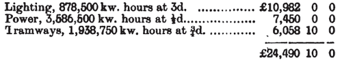 |
It may be asked why the tramways are charged fd. per unit. The reason is that all the rotating machinery, battery, and half the switchboard in converter station is solely for tramway purposes and necessitates the wages of three extra attendants.
In Dunedin, the summer evenings are long and the twilight lasts till 9p.m. Nearly all the shops close on ordinary week-nights at 6 p.m. and at 9 p.m. on Saturdays; the large retail houses mostly close at 1 p.m. on Saturdays. For these reasons, and bearing in mind the probable nature of the load factor and the anticipated diversity factor, the writer did not recommend any "flat lighting rates," and fixed the high rate on the "maximum demand system" for 1 1/2 hours per diem. This system of charging, considering the latitude of the locality, is undoubtedly the fairest to the long-hour consumer, as the larger shops and retail houses would only require lighting during about four months of the year from 4 p.m. to 6 p.m., Saturdays and Sundays excluded, and, as the capacity of the generating plants, mains, &c, has to be sufficient to supply consumers of this class for such short periods of the year, it follows that there should be a wide range between the high and low rates of the "maximum demand system." The large shopkeepers, therefore, will pay 5d. per unit, but the small householder, who will probably keep all his lamps running for an average of three hours per night throughout the year, will pay 3d. per unit.
With a hydro-electric plant of this nature the capacity is absolutely limited to the quantity of water available, and the object of a scale of charges such as shown in the diagram is to induce large consumers to keep off peak-load hours. Several good power consumers have been secured, such as cement works, 250 H.P., 24 hours a day; rope works, 150 H.P., 16 hours a day; newspaper offices, 300 lamps and 70 H.P.; railway station, 60 kw.; and the annual income derived from the above is estimated at £13,500. The rates had to be cut very fine in order to compete with the extraordinary statements made by the exploiters of suction-gas plants.
* Abstract of a Paper read before the Electrical Association of New South Wales.
