[Trade Journal]
Publication: American Institute Of Electrical Engineers
New York, NY, United States
p. 18-45, col. 1
BURNING OF WOODEN PINS ON HIGH-TENSION
TRANSMISSION LINES.
BY C. C. CHESNEY.
Facts concerning a number of examples of the burning of wooden insulators pins and a recommendation as to the use of iron pins.
In this country it has been almost the uniform practice in high-tension pole line construction to use wooden pins. The reason for their use has been the belief that because they were made of wood they strengthened the entire insulation of the pole line system, and were in consequence additional safeguards. These pins have generally been made of locust, oak or eucaliptus [sic] eucalyptus; and in order that the insulation might not deteriorate from the action of the weather, they have usually been treated carefully with hot asphaltum, paraffine or linseed oil. The temperature and character of the treating liquid have depended more or less upon the whim of the constructing or designing engineer. Although there has been no uniform method followed and although/ the materials used in the treatment have differed greatly, the results have been universally the same. Wood pins when used with glass or well vitrified porcelain insulators, have given very good service on potentials as high as 25,000 or 30,000 volts. There have been no unusual pin troubles at these voltages which could not readily be explained by porous or cracked insulators or by some peculiar climatic conditions. In my opinion, the success secured in the operation of the great majority of these lines is due to good insulation of the insulator, and the insulation of the pin has in reality contributed very little to that success. For 40,000 volts and for higher potentials, the insulators offered by all manufacturers do not have the same factors of safety as the insulators for lower voltages offered by the same manufacturers. The difference is not so much in the thickness or in the quality of the glass or porcelain used; it is more particularly in the general shape of the insulator and in the dimensions of the insulating surfaces and petticoats. For this reason, even under severe local surroundings, the 10,000, 15,000, 20,000 or 30,000 volt insulators have shown very little surface leakage and in consequence there has been comparatively little pin burning at these voltages. It is true that in localities of salt storms, of heavy sea fogs or chemical factories, there has been more or less pin burning without regard to the type of insulator used, or to the potential of the system. The writer has been informed that a certain plant using only 440 volts has at times great trouble from the burning of pins, although 10,000 volt insulators are used. This trouble is due entirely to the deposit on the insulators from a neighboring chemical factory, and as might be expected their period of no-burning is during the rainy season.
 |
| Fig. 1. |
 |
| Fig. 2. |
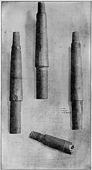
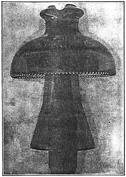
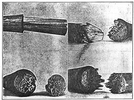
These instances however, are rare, and when the cause is apparent, the remedy is usually at hand. The pin burning on 40,000 and 50,000 volt lines is somewhat different. Eliminating all causes due to broken or defective insulators, the actual flow of current over the surfaces and through the body of the pin is probably very small. On the lines from which the writer has secured burned pins two used 11-inch Locke insulators, as shown in Figs. 1 and 2; the third used the Redlands type, Fig. 3. The first two lines were operated at a potential between 45,000 and 50,000 volts, and the pole and occupied the relative positions as shown in the cuts. The burned sides stood towards the damp winds from the ocean. Fig. 6 shows a burned pin of the type shown in Fig. 2. Fig. 7 is the Locke iron-pin with porcelain base (Fig. 3) taken from a 33,000 volt line. The striking feature is the burning of the wooden thread to the iron pin. The writer has been informed by the general superintendent of this plant that every pin that has been examined on this line is burned in exactly the same way, yet third at about 33,000 volts. The pins shown were taken from perfect insulators and in some cases the insulators were immediately put back on the line. Pins shown in Figs. 1 and 2 were made of eucaliptus [sic] eucalyptus and boiled in linseed oil. The line using pin shown in Fig. 2 also used a porcelain sleeve covering the base of the pin. Fig. 3 shows the well-known Locke iron-pin with porcelain base and oak thread. Fig. 4 and Fig. 5 show three pins all of the type shown in Fig. 1.
 |
| Fig. 3. |
| |||
| Fig. 4. |
| |||
| Fig. 5. |
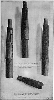
These pins were taken from the same there has been comparatively few punctured insulators and no cross-arms burned from the current leaking over the surface of the insulators. Fig. 8 shows the pin taken from the same 50,000 volt line as those shown in Fig. 4. This pin is shown sawed in sections in Fig. 9. The noticeable feature is that the burned section is entirely in the upper part of the pin about 1 3/4" below the thread. The outside surface and the centre of the pin below this point shows no charring. It would appear that at least in this instance the burned section was the point of highest resistance of the pin, and that the lower part of the pin was a good enough conductor to permit the small current which leaked over the surface of the insulator to flow without any special generation of heat in that section of the pin. The reduced insulation of the pin and insulator was no doubt due to the dust and fog. The upper portion of the pin, being better protected by the insulator from fog and dust, had in consequence higher surface resistance. The dark spot shown on the right hand edges of the lower section of Fig. 9 is the sap section of the wood and has been discolored by the linseed oil boiling which the pin originally had. This section has been in no way affected by the current. In Fig. 9 is illustrated a peculiar action which is occasionally found on high tension transmission lines, and which, for a better name, has been called "digesting the thread of the pin." The thread of the pin softens while in service and may be rubbed off with the fingers. This soft wood has a sour taste and resembles digested wood pulp. This action is not necessarily accompanied by the burning of any portion of the pin.
The evidence here presented, while not conclusive, still points to the advisability of using iron pins with modern insulators properly chosen for the line potential.
 |
DISCUSSION.
PRESIDENT SCOTT:The subject of the meeting this evening is Power Transmission on High-Tension Lines.
There are a number of different subjects to be presented; these have been prepared by the members of the Transmission Committee as introductions to discussions, not as complete, formal and exhaustive papers in themselves, but written with the intent of calling attention to and introducing a number of points on the several subjects which would lead to contributions from others. Mr. Mershon and I think that the best method of conducting the meeting this evening would be to take up each subject in turn and to devote a specified time to it, so that some attention could be given to all. The gentlemen having the subjects in charge will have a certain amount of time at their disposal. They can present the written material first and then the subject will be open to general discussion for the remainder of the half hour which will be allotted to each of the subjects. The first topic is "Mechanical Specifications for a Proposed Standard Insulator Pin," by Ralph D. Mershon.
MR. RALPH D. MERSHON:Before the discussion is begun, I wish to state that my object in writing this introduction was to get a discussion sufficiently full to form the basis of recommendation to the Standardization Committee.
There are a number of written contributions which I shall read. The first is from Mr. M. H. Gerry, Jr., of the Missouri River Power Co.
MR. M. H.GERRY, JR.It is too early in the development of high-tension transmission to attempt to make standard the details of construction. Such action at this time by the INSTITUTE would result not only in failure, but in a tendency to prevent advancement in this line. However, a full discussion by the membership cannot fail to be of great advantage and profit.
 |
| Fig. 1 and Fig. 2. |
Mr. Mershon has suggested the adoption as standard of certain forms of wooden pins, the designs of which conform to common construction. Most engineers of experience, however, would be in favor of a diameter greater than one inch at the top of the pin, and a greater length of thread than two and one-half inches. Wooden threads most frequently fail by shearing, and the strength in this particular is greatly increased by a larger diameter of pin, and a greater length of thread. The longer thread is an advantage also in preventing the insulator from tipping out of line, when the fitting is loose between the thread of the pin and that of the insulator.
 |
| Fig. 3. |
 |
| Fig. 4. |
 |
| Fig. 5. |
The shoulder of the pin, as suggested by Mr. Mershon, has certain disadvantages for heavy construction. On account of the rounding off of the top of the cross-arm, this form of shoulder does not bear well, as shown in sketch, Fig. No. 1, and the sharp corner at the point of greatest strain, introduces an element of weakness. In Fig. No. 2, a form of shoulder is shown which has been used by the writer with considerable success. This shoulder tapers at an angle of 60°, and fits into a counter-bore in the top of the cross-arm. With this design the pins may be driven to a firm bearing at the top of the cross-arm, which has the effect of steadying them and increasing the strength of the construction at this point.
In lieu of the form of thread proposed by Mr Mershon, the writer suggests that shown by sketch, Fig. No 3. In this design the square top of the thread is as wide as the groove, resulting in increased area of wood to withstand shearing strains. The threads of the insulators are always stronger than those of the pins, and for this reason the form of thread as proposed has considerable advantage. This form of thread may also be easily cut, in either seasoned or unseasoned wood, and the depth not being so great the pin is stronger at the bottom of the thread.
Figs. No. 4 and No. 5 are drawings of the high-tension pins now used by the Missouri River Power Company. They show the form of the thread and of the shoulder as described above, and also give the general dimensions of the pins. The upper shoulder as shown by the drawings is for the support of a glass sleeve, which is used to protect the pin from the weather. Fig. No. 6 is from a photograph of the 50,000 volt line insulator assembled on one of the pins.
| |||
| Fig. 6. |
MR. MERSHON:The next written contribution is by Mr. William R. C. Corson, Electrical Engineer, of Hartford, Conn.
MR. WILLIAM R. C. CORSON:I believe I am only concurring with the general feeling in expressing my pleasure that our Committee on High-Tension Transmission has seen fit to commence its work by an effort to standardize an essential element of construction, and in hoping that this line of effort may be continued and result in recognized and approved standards for all other items capable of a general determination.
Mr. Mershon's method of developing the table of dimensions of the proposed pin is so rational that criticism of it is difficult. Briefly stated, of course, this method assumes the pin in general use as a basis, and mathematically determines the diameters of pins of differing length, which shall be capable of sustaining the same tension at their extremity as will this pin. In other words, the safe load that may be applied at the top of the proposed pins is of constant value in all. This value is not discussed in the "Introduction," and feeling that its determination would be of interest to me, and might prove of value, I have made a series of tests in a Sellers' machine to ascertain the value of S in equation (1,) for the ordinary locust pins, under the actual conditions of support suggested.
Six standard locust wood pins were selected at random from a supply at hand. The larger diameter of the shank varied from 1 7/16 inches to 1 1/2 inches, while the smaller diameter was uniformly 1 11/32 inches. These were supported in a 1 1/2 inch hole in a hard wood block, and the measured tension applied about 4 1/2 inches from the block, the exact distance of the point of application being measured.
The load was very gradually applied in increments of a few pounds, and the amount noted when the first separation of the fibre appeared. Most of the specimens showed distress at from 700 to 750 lbs., with maximum strength of about 10 per cent. above this. One specimen, however, showed a crack at 600 lbs., and an ultimate strength of 1083 lbs. The average value of S determined from the tension at which the first fibre separation appeared was 11,130 lbs. per sq. inch, and the average value calculated from the maximum loads sustained was 13,623. The value of s, calculated for the specimen crackling at 600 lbs., was 9,280. While this is somewhat below the average due to an apparent defect in the wood, it is probably best to assume that for a maximum load, s should not be greater than 9,000. Assuming this value, the maximum load that may be applied to the proposed pins at a distance from the cross-arm equal to the designation of size, would be as follows:
 |
Of course these values of P would be identical but for the difference between the actual diameter selected and that of the theoretical pin. The average value is 636 lbs., which may be considered the maximum load that the standard pins will sustain at the point designated.
Even with very generous factors of safety, it would appear that the pins suggested would prove of ample strength to withstand the side strains to which they may be subjected. For heavy work and for end poles, an insulator carrying the wire at some distance below the top of the pin would, of course, increase the strength of the construction. A table of standard insulators could perhaps with advantage be prepared so proportioned between groove and bottom of threaded bore as to maintain the stress on the pin within the allowable safe values for the various tensions applied.
I would call attention to one seeming error in the table of the dimensions of the proposed pins. In the paragraph headed "Designation," the following appears: "It is proposed to designate that portion of the pin above the cross-arm as the 'stem' of the pin," and further, "It is proposed to designate a pin by the length of its stem." From this definition the stem of the pin would have a length equal to the sum of the dimensions A and G of the table. For the five-inch pin shown in the table this would be 5 1/4 inches, and thus is not equal to the designation.
MR. MERSHON:Another written contribution to this discussion is by Mr. C. L. Cory, of San Francisco.
MR. C. L. CORY:The mechanical strength of insulator pins for use on long distance transmission lines has been given much consideration by electrical engineers in California during the past six years. For the most part the insulator pins in use are wood. On the 33,000 volt, 83 mile, double circuit, three-phase transmission line of the Edison Electric Co., from their Santa Ana power house to the city of Los Angeles, iron pins with porcelain sleeves are used. This transmission is the most notable system in California at the present time using insulator pins other than wood.
Eucalyptus has been found to be perhaps the best wood to use for insulator pins. After being turned up and threaded, they are usually treated with hot linseed oil. This treatment is desirable more on account of the protection which such treatment gives the pin against weather than on account of the insulating qualities of the oil or oil treatment.
It should be understood in this connection that an insulator pin should be depended upon only to support the insulator. The insulator in turn should be depended upon to provide the necessary insulation for the line wires. No pin after being in use for a few years on a pole line can maintain to any marked degree the insulating qualities originally existing, due to such oil or paraffin treatment.
The tests outlined below were made in the electrical laboratory of the University of California, for the purpose of determining how near the pins generally in use in California conform to the proposed standard pins suggested by Mr. Mershon. In the test twenty-two pins were broken. These were not selected particularly for the test, but were taken at random from a large lot of such pins which were to be used in construction work. Of these, twelve were of the size generally in use on transmission lines where the voltage does not exceed 30,000 volts. These pins are 11 1/2 inches long, including shank and stem, the latter being 6 7/8 inches in length. The other ten pins tested were of the size used on the lines of what has been known as the Bay Counties Power Co., now the California Gas & Electric Corporation, and the Standard Electric Co. The line voltage in each of these transmission systems is from 40,000 to 60,000 volts. These pins are 15 3/4 inches long, including shank and stein, the latter being 10 1/8. inches long. All of the dimensions of the pins tested are given in Figs. 1 and 2.
 |
| Fig. 1. |
These pins do not exactly conform in size or length of stem with any of the proposed standard pins. Below, however, is given the comparative dimensions of the two samples of pins tested and the nearest sizes of the corresponding proposed pins. For sake of comparison, a 7-inch pin, as proposed, is contrasted with the 6 7/8 inch tested pin, and the 11 inch proposed pin is contrasted with the 10 1/8 inch tested pin. The above dimensions refer to the length of the stem of the pin, as suggested by Mr. Mershon.
 |
In general, it will be seen that the dimensions of the proposed and tested pin agree fairly well. The most marked difference is in the diameter of the portion of the pin which is threaded to receive the insulator. It seems evident that one inch is not a sufficient diameter for the thread of the pin for all sizes. If there is any burning of the pin just below the insulator, the inevitable result will be breaking at the bottom portion of the thread. Such a break will usually leave the pin, except the threaded portion, standing in the cross-arm, while the insulator with the threaded portion of the pin inside, will hang suspended on the line wire. This sort of break has often been observed on high-voltage transmission lines.
 |
| Fig. 2. |
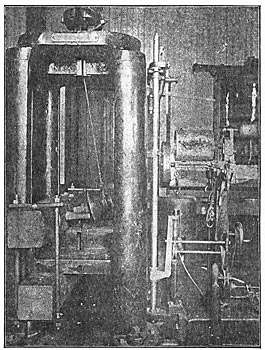
The method of testing the pins is clearly shown in the accompanying photograph. It was impossible to mount the cross-arm in the testing machine so that the strain on the pin would be at right angles to its axis. The variation from a right angle, however, is small and to a certain degree conforms with the direction of the strain on the pin, due to the sag in the line wire. The "breaking load," as given in the tables below, refers to the strain in the direction of the cable, while the "real breaking load" is the component of this strain at right angles to the axis of the pin.
 |
The average results, referring to the "real breaking load," of the tests of the two pins are respectively, 1085 pounds for the 6 7/8 inch pin and 2310 pounds for the 10 1/8 inch pin. The character of break in the two pins, however, is not the same. Almost without exception, the 6 7/8 inch pins were broken approximately square off at the cross-arm. The larger pins, however, split in the stem, the beginning of the split being just at the bottom of the thread. An inspection of the photographs clearly shows the difference in the character of break in the two pins.
| |||
| Method of Mounting Cross-Arms, Pins and Insulators in Testing Machine. |
It seems from the tests that the shank is the weakest part in the 6 7/8 inch pins, while the stem, and particularly the upper portion of the stem, or thread, is the weakest part of the 10 1/8 inch pins.
The variation of the "real breaking load" for the different 6 7/8 inch pins tested is from 705 pounds minimum to 1360 pounds maximum. For the 10 1/8 inch pins, this variation is from 1475 pounds minimum to 3190 pounds maximum.
During the progress of the test, it was observed that the "allowable breaking load" was least when the pin was turned in the cross-arm, so that the strain was across the grain of the pin, while the greatest allowable "breaking load" corresponded with the position of the pin in the cross-arm, so that the strain was parallel to the grain of the pin. In the tests made, no particular care was taken to turn the pins in any fixed position relative to the grain of the pin and the direction of the strain applied.
For good construction on lines using 30,000 to 60,000 volts the larger pin must be used. It does not seem, however, that any good reason exists for a great number of different sizes of pins, as it would seem probable that the two sizes tested might be used to fulfil almost every requirement for transmission work where wooden pins are at all allowable.
In many respects an iron pin is better than one of wood. In the first place, to secure sufficient strength in the shank, the wooden pin must be of such a large diameter that the size of the cross-arm is necessarily increased. In addition, using an iron pin, the insulator can be held down on poles or supports where the tendency of the line wire is to raise or pull the pin out of the cross-arm. In using wooden pins, this is usually prevented by driving a nail through the cross-arm into the shank of the pin.
An iron insulator pin, possessing many desirable features, has been designed for use on the extensive transmission lines of the Vancouver Power Co., of Vancouver, British Columbia, the design being due to Mr. Wynn Meredith, of San Francisco. In general, the pin consists of a steel bolt approximately 12 inches long. A cast iron sleeve 4t inches long, and fitting closely to the cross-arm, fills the space between the thread, and corresponds to the stem of the ordinary wooden pin. The thread of the pin is made of lead, this lead thread being cast upon the end of the steel bolt, the steel bolt being first chopped or made ragged, so that the lead is held firmly to the steel bolt after being cast.
The tests upon this form of pin have not as yet been completed, but as soon as possible the results will be presented to the INSTITUTE.
MR. MERSHON:The fourth and last written contribution to this part of the subject is by Mr. D. L. Huntington, electrical engineer of the Washington Power Company, Spokane, Wash.
MR. D. L. HUNTINGTON:Wooden pins are subject to so many uncertainties when used in connection with very high voltages, especially where the atmosphere contains salt, smoke or dust, that it seems desirable to abandon their use for such purposes wherever possible, and to substitute a metallic pin. The construction of a long distance line for 60,000 volts, led the writer to make some investigation as to what could be done in this direction, without excessive cost.
It was decided that a drop-forged or a turned steel pin would be so expensive as to exclude it, even if the time at our disposal would have permitted us to wait for its delivery.
Experiments were made with a cast-iron pin almost identical in dimensions to that shown in Fig. 2 of Mr. Chesney's paper, except that it was cored out internally so as to make its weight about 10 pounds. The diameter of the shank was 2k inches. This pin, before fracturing, sustained a load slightly in excess of 3,000 pounds, suspended from near the end of the threaded portion.
Fear was felt, however, as to what might occur under the sudden strain of a line parting in winter time, with the possibility of the fracture of several pins at a time due to the sudden shock.
To avoid this, several designs were made of pins cut from round steel bars of 1 inch and 1 1/8 inch diameter. The difficulty in obtaining a satisfactory shoulder for the pin at the cross-arm proved serious. Furthermore, it was feared that with a pin of that small diameter, the cross-arm would be likely to burn out at the pin-hole, as the interior surface of the hole would be comparatively small for distributing the leakage currents to the cross-arm. Moreover, actual experience with wooden pins has shown more or less conclusively that with a shank diameter of two inches or greater, there is little or nothing to fear from this trouble.
 |
| Fig. 1. |
As a result of these several difficulties we have designed and adopted a pin (see Fig. 1) eighteen inches long, made of 1 1/8 inch round mild steel bar, and having a shoulder and shank cast upon it as shown. This pin we find will begin to bend when loaded with about 1,000 pounds at the upper end, the shank being rigidly supported. This is much lower than the results obtained by the cast iron pin referred to above, but it is believed that it is more reliable and that it is sufficient for nearly all ordinary work. In addition, the steel bar will not snap off under sudden shock, but will support the insulator and line safely even when badly bent. We were unable, in the time at our disposal, to investigate what could be done in the way of malleable castings of a design somewhat similar to the cast-iron pin mentioned above, but it is the writer's opinion that it would prove a fruitful line of investigation.
High freight rates of the west and a higher initial cost will doubtless make some of those in charge of the construction of such lines hesitate at the extra expenditure (in our case it was about double the cost of eucalyptus pins), but it is in the line of safe and conservative engineering and certainly strengthens the weakest link in our high-voltage chain, our lines.
MR. W. N. SMITH:-It seems to me that the dimensions given are all very well for a pin carrying a certain weight of wire, but it does not seem to me that a single standard table of dimensions could be laid down to cover anything like all the conditions of various power transmission lines, all the way from a line of 5,000 or 6,000 volts, with, say, No. 4 wire, up to one like the Niagara Falls power transmission line, which is of 300,000 c.m. cable. The scheme of the tabulation should be enlarged and gone over carefully, so as to have a separate tabulation for a reasonably small range of weights of copper wire to cable; that is, one table for sizes from No. 6 to No. 3, another No. 3 to No. 0, another from No. 0 to No. 0000, and another from No. 0000 up. In this way the design of a standard pin would more nearly meet the varying conditions of transmission line construction. I remember reading Mr. Stillwell's paper a year or more ago on the Niagara Falls transmission plant, in which, if I remember correctly, he stated that the principal trouble with pins was their breaking at the root of the thread. I do not see that this point has been covered in Mr. Mershon's discussion, although it was referred to in Mr. Gerry's contribution. I should think it a matter of considerable importance in the design of the pin. I further agree with Mr. Gerry in his opinion that the top of the pin is rather small, certainly, for the very heavy insulators that would be required for a transmission above 30,000 volts.
MR. P. H. THOMAS:It would be a great gain to those who hope to get information from the report of the committee, if the characteristics of the different types of wood commonly used could be discussed, e.g., oak, eucalyptus and locust. It is to be hoped that in the local sections this question will be very fully discussed. Also, something should be said about the method of treating pins, which is one of the most important questions in the insulation of the line. The treating of pins to make them waterproof, without injuring the mechanical strength, is a difficult matter.
In putting up an insulator, where the pin comes to a bearing on its end inside of the insulator, expansion of the pin or contraction of the insulator may crack off the top of the insulator, especially with glass. To amend this difficulty, a shoulder might be arranged so that the pin would not touch the top of the insulator.
MR. MERSHON:--As to the question of the size of the pin, it may be desirable to have a pin larger at the top, perhaps, but I do not think the reason which has been given for this holds very well. In the first place, an insulator properly designed will not tip. If the insulator is designed so that the side pull of the line on it is transmitted directly to the pin, instead of being all the way from an inch and a half to two inches above the top of the pin, as in the case of most insulators, it will not tip. If it does, that is a fault in the design of the insulator and not in the dimensions of the pin. Mr. Gerry has criticized the shearing strength of the thread. I doubt if the thread of the pin proposed by Mr. Gerry will have a greater shearing strength than the thread of the pin referred to in the paper. The question of the shearing strength is not so important. A well-designed line will not have much up-strain. A line with much up-strain is not laid out as it should be. You cannot prevent some up-strain on some insulators, but it may be made so light that the shearing strength of the thread will not be of much importance.
VICE-PRESIDENT SHELDON:If there is no further discussion, we will proceed to the next paper. Do you care to make any closing remarks, Mr. Mershon?
MR. MERSHON:There was a further remark made by Mr. Gerry to the effect that it is too early to adopt a standard pin. I think if we adopted a standard and changed it from year to year, we should not be any worse off than we are now, when we have no standard. There are as many standards as there are manufacturers of pins and designers of pole lines. The only way now to get a pin to fit an insulator is to send the insulator to the pin manufacturer and in that way have the pins made so that they will fit. If you buy a pin from one manufacturer and the insulator from another, they may fit, or they may not fit.
VICE-PRESIDENT SHELDON:We will now proceed to the discussion of the paper by Mr. F. O. Blackwell on "The Testing of Insulators." As Mr. Blackwell is not present and has not delegated any one to present his paper, I will call upon Mr. Mershon to present the introduction.
MR. MERSHON:-If there is no objection, I will pursue the same course in regard to Mr. Blackwell's introduction as with my own. I will omit reading his introduction and read the contributions to it. 1 think they take up most of the main points and wilt serve as a basis for the discussion this evening. The first contribution is by Mr. M. H. Gerry, Jr. It is as follows:
MR. M. H. GERRY, JR.Mr. Blackwell has ably discussed a number of important matters in connection with the testing of high-voltage insulators. There are, however, a number of additional points which have not been touched upon.
Insulators are tested for two purposes: first, to determine the design, shape, material and dimensions best suited for a given voltage and set of conditions; secondly, insulators are tested as a matter of routine, to determine whether manufacturers have complied with specifications regarding material and workmanship.
There can be no complete set of tests to cover the first purpose, as it is not only a matter of experiment, but of skill and judgment in properly interpreting the results of many tests, in relation to service conditions. The testing of insulators for the second purpose is comparatively simple. For glass insulators it is usually sufficient to inspect them for physical defects, such as cracks, bubbles and incorrect dimensions. A certain percentage of the insulators should also be tested for proper annealing, and for mechanical strength. A chemical analysis of the glass of a few of the insulators is also desirable. Electrical tests of glass insulators are unnecessary, as the physical inspection will reveal everything that can be found by an electrical test. Porcelain insulators are more difficult to test than are glass insulators, on account of many defects being covered by the glaze. For very high voltages, porcelain insulators should be tested electrically, and should also be carefully inspected during the process of manufacture, and before the glaze is applied. This is especially desirable with insulators built up of several parts and cemented together by glaze or other material. Defects in insulators of this type are difficult to detect, even by electrical tests, unless they are pronounced.
Mr. Blackwell has indicated the proper method of making electrical tests of insulators. The puncture test mentioned by him, of twice the potential between wires, is usually sufficient, but a higher test is desirable where the insulators are to be exposed to severe lightning strains.
MR. MERSHON:I would like to speak in regard to the following sentence in the contribution of Mr. Gerry, which has just been read. "The puncture test mentioned by him (Mr. Blackwell), of twice the potential between wires, is usually sufficient, but a higher test is desirable where the insulators are to be exposed to severe lightning strains." I have never personally known or heard of a case of insulators having been punctured where the puncture could be laid to lightning. It seems to me the lightning would flash around most insulators rather than puncture them.
Then as to the question of the chemical analysis of glass insulators. I have never had any reason to think that the chemical composition of the glass made any difference in the behavior of glass insulators. I have made tests for difference in behavior due to composition on both insulators and tubes of glass, but never succeeded in finding any.
VICE-PRESIDENT SHELDON:The subject is open for general discussion.
MR. P. M. LINCOLN: I would take issue with Mr. Gerry, who made a statement that glass insulators did not need testing beyond visual inspection. I know of a certain line, the insulators of which were not given a voltage test, but were simply tapped with a mallet in order to eliminate, if possible, any which had undue internal strains. After the insulators were up and the normal voltage applied, quite a number of them broke down in actual service, which probably would not have occurred if they had been tested with voltage before being erected.
Another point, in regard to lightning, which Mr. Mershon speaks ofit is a fact that rain usually accompanies lightning storms, and that, of course, will give you a wet surface on the insulator. This wet surface is a very good conductor of the sudden surges which occur in lightning storms, so that lightning strains will be very apt to go over the surface rather than through the insulator. I do not think there is much danger of breaking lown of an insulator from lightning strains, after a test of double normal potential has been applied.
VICE-PRESIDENT SHELDON: Is there any more discussion?
MR. W. N. SMITH:While the subject is before the INSTITUTE, I think it would be quite interesting if any members present would state their preferences between porcelain and glass for high-tension insulators. It is a question that comes up every now and then, and no doubt there are members present who may have a very strong leaning toward one or the other material for high-tension transmission.
MR. MERSHON:As between glass and porcelain, it seems to me about the only advantage, other things being equal, that porcelain has over glass for transmission work is that of mechanical strength. Sometimes it has that advantage and sometimes it has not. It is a fact, however, that in some forms of insulator in some complex formsit is possible to get the porcelain insulator cheaper than the glass one. I have found this true, to my surprise, in one or two cases. When the insulator is large, so that it takes the form of a very heavy central portion of glass, with long, thin petticoats, it seems to be almost impossible to make it of glass and have it symmetrical. The thinner portions cool first, and when the insulator is taken from the mold the weight of the outer portions distort the inner portion of the insulator, which is still hot. An advantage has also been claimed for porcelain over glass because of the lesser hygroscopic effects, but I think in most power transmissions the small amount of power necessary to dry up whatever moisture will get on the surface of the insulator in that way would not be serious. As a matter of fact, in any measurement I have ever made, no difference could be detected between porcelain and glass in the matter of losses over their surfaces at high voltages.
MR. T. W. SHOCK:I had the pleasure of building a line this last year in the State of Pennsylvania, in which I used an insulator which tested for 75,000 volts. The ordinary pressure will be 24,000 voltsthat gives a factor of safety of over two. I think I agree with Mr. Blackwell, that in testing insulators for a line of high pressure the testing pressure should be at least two and possibly three times the ordinary line pressure. My idea in adopting that style of insulator is due to the fact that it was built for a line on the Pacific coast, for 40,000 volts, and I adopted it to give me an extra factor of safety. I made the test at a pressure of 75,000 volts. I think the insulator will give us very good satisfaction.
MR. F. N. WATERMAN:Mr. Blackwell's reference to testing a double insulatoran insulator primarily of two parts chance of being sound is required to be tested twice. The test peculiarly required by the double insulator is the mechanical test, and as far as my observation goesI have tested a good many of themif they are substantially free from large air spaces, they will stand up under the final electrical test. It seems to me that the requirement of a double test is unfair and unnecessary.
 |
| Broken 10-1/8" Pins (Stem) Total Length, 15-3/4" Showing How Pins Split. |
MR. THOMAS:Mr. Gerry, Mr. Lincoln and Mr. Mershon have referred to one point in the testing of glass insulators that deserves a good deal more consideration, and that is the initial strains left in the manufacture and annealing of the glass. The breakage of glass insulators on the line during service may more often be due to too much sun on one side of a poorly annealed insulator than to electrical strain. I do not know of any test which has been suggested to determine whether glass has been properly annealed or not, but I do not doubt that some test could be gotten up, and I make the suggestion to the committee that they consider this point carefully. A successful test would save a great deal of trouble in high-tension lines after the insulators requiring that each part should be separately tested, seems to me practically to bar out double insulators and does net seem to be logically founded. He says, "if it is to be tested for 100,000 volts and is made in two parts, each part might, for instance, be tested with 70,000 volts. The object of this is to have the weak parts rejected before they are assembled." The objection to that, from a practical standpoint of course, is evident; but there is a further objection, not so evident, and that is, as I understand the porcelain people, in the baking or vitrifying of the two parts it is not desirable to take the entire shrinkage out on the first heat. Consequently, if the insulators are to be tested before being filled with glaze and re-vitrified, they are not tested at all in their final condition. Furthermore, I think it is illogical for the reason that it is a well-known fact that if we get porcelain in thin parts, we have a very much more than equal chance of getting sound porcelain. That is, if the same insulators were made in one part they would only have our final test, while the double insulator with much greater initial are installed. There is one rather old point which should be mentioned in the testing of porcelain insulatorsnot only should they be tested with salt water, but the regulator should soak a certain definite time; the Standardization Committee might determine how long.
MR. C. C. CHESNEY:--A glass insulator, if it is not properly and uniformly annealed, has unequal strains in the different parts of the glass. I have known a number of such insulators after a cool night to break when the sun struck them in the morning. The side towards the sun cracks off. Aside from this feature, I believe a glass insulator will give as good satisfaction as a porcelain one.
MR. MERSHON:--I cannot entirely agree with the author in regard to the use of one transformer for testing purposes. A series of transformers need not have a bad regulation or seriously distort the wave form, and such a testing set has a very great advantage that a transformer breakdown is much less serious than in the case of a single testing transformer. The knowledge of this fact gives one more confidence in testing, especially in experimental testing. For very accurate results in any case a step-down voltmeter transformer is desirable.
Neither can I agree that insulators should necessarily be tested on iron pins. As I have stated before, an iron pin is likely to be the means of putting upon the insulator a mechanical stress all out of proportion to any which it would meet in practice if installed upon a wooden pin. For instance, if the insulator be screwed down tight upon a metal pin there will result stresses in the head tending to force the top of it off either at one of the threads or at the bottom of the pin-hole, or tending to burst the head. In either case there is a resulting mechanical strain in the substance of the insulator inviting puncture perpendicular to the lines of stress. An insulator that will stand up well under a salt water test, will often break down quickly when tested on a metal pin. While I do not believe in depending upon the wooden pin for insulation, I see no good reason for condemning it in general where there will be no trouble from burning. The author says that wooden pins barn off eventually unless the insulator be good enough to be used with an iron pin. If the insulator be good enough to prevent-burning of the wooden pin, why not use the wooden pin unless there be some mechanical requirement which it cannot meet.
 |
| Iron-Pin Insulator. |
 |
| Parts of Iron-Pin Insulator. |
 |
| Parts of Iron-Pin Insulator. |
I agree thoroughly that any new type of insulator should be given a rain test; that is, a voltage test while water is being sprayed upon the insulator in imitation of rain. If a wooden pin is used in this test, it should be covered with tin-foil from a point inside the petticoat nearest the pin to a point two or three inches below. The voltage should be applied between the foil and a wire around the neck of the insulator, or, preferably, between the foil and. a piece of wire representing the line wire and tied to the insulator as it will be in practice. The recommendations of the Introduction as regards the angle at which water should be sprayed, is all right, if this angle be uniformly adopted in testing; but some definite angle should be adopted, as the angle makes considerable difference in the voltage at which the current will arc from the line wire to the pin. The recommendations in regard to the spray are not, however, so specific as could he desired. The amount of water sprayed, as well as the angle, makes a difference in the arcing voltage. Some time ago I endeavored to obtain from the United States Weather Bureau information as to the most violent precipitation on record in this country. The record sent me showed the most violent downpour as being about .8 of an inch in five minutes. The maximum rate of downpours during that time may, of course, have been greater than this. It has been my practice to endeavor to adjust the spray for a precipitation of one inch in five minutes. This can be most conveniently done by placing under the insulator a suitable pan and collecting in it the water for five minutes. Care must be taken that in placing the pan it does not receive water from any part of the cross-arm other than that just over it. The question of the method of obtaining the spray is one which it is well to consider. It is no easy thing properly to adjust the spray from an ordinary garden spray-nozzle or rose-spray and it is no wonder that uniform results are not easily obtainable. It is desirable, if possible, to have some special form of spray-nozzle which will give a uniformly distributed spray. This might perhaps be in the form of a very large rose-spray of a foot or more in diameter.
It is desirable that if possible we arrive at some definite decision this evening on the points mentioned in regard to the methods of testing insulators, so that recommendations can be made on this subject to the Standardization Committee.
| |||
| 1. Pin Split in Shank and Broken at Cross-Arm. 2. Pin Broken at Upper Part of Shank at Cross-Arm. 3. Pin Broken at Upper Part of Shank at Cross-Arm. 4. Pin Broken at Upper Part of Shank at Cross-Arm. |
VICE-PRESIDENT SHELDON:There is a written contribution on this subject from Mr. W. L. Waters, of Milwaukee, Wis.
MR. W. L. WATERS:The form of potential wave given by modern alternators differs very little from a sine wave. The worst case commonly met with is that of a three-phase alternator wound for high voltages. These machines have usually three slots per pole, and the wave form shows pronounced harmonics of five and seven times the fundamental frequency, but the effect of this distortion on breakdown voltage of an insulator is inappreciable. The only commercial machines that have wave forms which would affect the accuracy of the results to any extent are the old single-phase revolving armature machines with projecting poles on the armature, which show a pronounced third harmonic. But these machines are seldom met with now. The charging current in a test on insulators or an overhead line generally conforms more or less to the potential wave form of the alternator, and whether the current is lagging or leading the distorting effect on the wave form is slight, and with all ordinary excitation and loads on the alternator the effect on the insulator test will be inappreciable.
Generally speaking, an insulator will stand momentarily a voltage strain which, if continued long enough, will break it down; and. this time effect is most marked in solid insulators. A gas such as air does not show this. When air is going to break down under a given strain, it will do so almost as soon as it is applied, except where the insulation of the air is subsequently weakened by a violent brush discharge. Solids show this effect to the greatest extent, and liquids such as oil to a lesser extent. And I have found that in insulating materials where this effect is most marked, differences in wave form have little effect upon the breakdown voltage; it seems to be the mean voltage or possibly the r.m.s. voltage which decides the breakdown. In air the wave form has quite an appreciable effect, and the difference between a peaked wave and a flat wave may he as much as 20 per cent. of the sparking distance. Porcelain insulators show very markedly this time effect; they will stand a much higher potential if applied instantaneously than they will if applied continuously, and as far as can be seen from the experiments I have made, they appear to conform with the rule mentioned above, and are practically unaffected by wave form. The sparking distance in air, on the other hand, being considerably affected by wave form, shows at once the unsuitableness of using a spark gap as a voltmeter if there is any doubt about the wave form. And I have found that unless it was in the hands of a very careful and experienced man, a spark gap was not of very much use in accurate work. Using needles as electrodes, the voltage seems to vary so much with the condition of the points, the state of the atmosphere, the proximity of other high tension conductors etc., that consistent results cannot be obtained in ordinary work. Using amalgamated brass balls, one inch in diameter, gave better results, but they are far from satisfactory. I think there is only one really satisfactory way of measuring high voltages, and that is by means of a voltmeter transformer connected straight across the insulator being tested. This method is accurate and is direct reading, and there is no chance of mistake and no continual trouble fixing and adjusting your spark gap. Reliable voltmeter transformers can be made for all ordinary voltages for a few hundred dollars, and the use of one would save its cost in worry and hard work in a very short time.
The above remarks are, strictly, only applicable to voltages up to 50,000, as I have had no experience with higher voltages. But I think that with slight changes they will apply to the highest voltages at present in use.
VICE-PRESIDENT SHELDON:We will now take up the paper by Mr. P. M. Lincoln, entitled, "Transposition and Relative Location of Power and Telephone Wires."
Mr. Lincoln read his introduction (see page 11), and the following contribution by Mr. M. H. Gerry, Jr.
MR. M. H. GERRY, JR.:Mr. Lincoln has discussed the most important requirements of telephone construction in connection with high-tension transmission lines. There is no especial difficulty in installing a successful telephone circuit which will give satisfactory service and reasonable safety in operation on a pole line carrying from 50,000 to 60,000 volts.
Mr. Lincoln has mentioned the principal requisites of successful design, which are a proper adjustment of the capacity, a maintenance of high insulation from ground, and a complete transposition of the telephone wires in reference to each other, to the power circuit and to the ground. In addition, might be added the use of certain safety devices, which reduce the danger in handling telephones connected with circuits on high tension pole lines.
In regard to transpositions! Mr. Lincoln advocates the transposition of the telephone wires only, but it is desirable also to transpose the main power circuits, in order to reduce to a minimum the voltage to ground on the telephone circuits. But few transpositions of the power circuit are required, and the service as a rule is materially improved thereby. Where there is considerable lightning, arresters should be installed on the telephone circuits of a design similar to those used on lighting circuits. The ordinary telephone lightning arrester is an undesirable and unsafe piece of apparatus for this purpose. Fig. No. 7 is a sketch of a telephone arrangement devised by the writer, which will give excellent results in service. Especial attention is called to the short gaps across the line, to the location of the lightning arresters, and to the repeating-coils, which should be insulated for at least 5,000 volts, and may be immersed in small glass jars containing transformer oil.
 |
| Fig. 7 |
The Missouri River Power Company, with which the writer is connected, regularly maintains a very satisfactory telephone service on its 50,000 volt transmission lines between Canyon Ferry and Butte, a distance of sixty-four miles, and this service is rarely interrupted, even during the most severe lightning disturbances. Under normal conditions, there is no potential on this telephone line, and only the slightest hum can be detected.
(the article is continued in 10272)
