[Trade Journal]
Publication: American Institute Of Electrical Engineers
New York, NY, United States
p. 65-78
(continued from article 10272)
DISCUSSION AT PITTSBURG, APRIL 9, 1903.
Programme.
The meeting was called to order by Chairman P. M. Lincoln.
1. Introductory Remarks.President C. F. Scott.
2. "Mechanical Specifications for Proposed Standard Insulator Pin," by Ralph D. Mershon, read by W. K. Dunlap.
3. "The Testing of Insulators," by F. O. Blackwell, read by C. E. Skinner.
4. "Transposition and Relative Location of Power and Telephone Wires", by P. M. Lincoln.
5. "Burning of Wooden Pins on High-Tension Transmission Lines," by C. C. Chesney, read by E. M. Tingley.
The discussion was participated in by C. E. Skinner, S. P. Grace, P. M. Lincoln, H. Etheridge, C. W. Rice, Mr. Bedell, P. H. Thomas, B. Frankenfield, J. S. Peck and President C. F. Scott.
MR. SKINNER:I have always been under the impression that for glass insulators a potash glass would give better results than a lead glass. This impression has not been thoroughly proved by test. Mr. Blackwell says that the striking distance of a given e.m.f. is greater at high altitudes than at low altitudes. If the striking distance is to be used by the INSTITUTE as a measure of the e.m.f., some figures should be obtained showing the variation of striking distances with the variation in the height of the barometer.
In early high-tension work the question of surface leakage over the insulator was considered of very great importance, and many of the earlier designs of insulators included an oil cup underneath to give a higher surface resistance. As far as I am aware, this construction has not been used on any of the long-distance transmission lines in the United States, and later practice has proved that such a device is entirely unnecessary. It is objectionable because it is soon filled with foreign substances and defeats the object for which it was designed.
The method of regulating the voltage of the testing transformer should receive consideration. There are three methods which have been followed, viz: first, by varying the field of the generator; secondly, by the use of a resistance in series with the low-tension side of the testing transformer; thirdly, by varying the voltage on the low-tension side of the transformer by means of a regulator dial connected to a suitable regulating transformer with a number of taps brought out from its secondary winding.
The first method can be used only where a generator is provided exclusively for this work. In the second method a water rheostat is usually employed. This gives a very smooth variation in e.m.f., and while unwieldy and requiring constant attention during the test, it is capable of giving very good results. The third method requires that the voltage on the high-tension side be changed by comparatively small steps, which may be done with proper regulating dials without opening the circuit. Steps even as great as 5 per cent. are not considered particularly harmful in the testing of insulators.
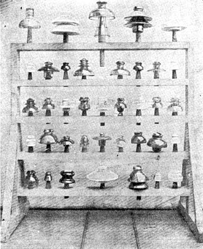
I am pleased to be able to show you an exhibit of insulators intended for high-tension work. This exhibit is not complete by any means, but shows a number of types which are in use at the present time. Most of these insulators have been given a test which may be briefly described as follows: the insulators were placed on the standard-size pin, the pin being wrapped with tin-foil. A photograph of the insulators (Fig. 1) as they appeared on the testing rack after a snow storm is submitted as part of this discussion. The test was made by applying the high potential from a testing transformer, the voltage of which was regulated by means of a regulator dial giving very small steps. The testing voltage was applied between a "tie" made in the ordinary manner and the tin-foil coating of the pin and the test was made under different weather conditions. The breakdown test was repeated at intervals for a period of some months, beginning about the middle of February and ending about the first of July.
|
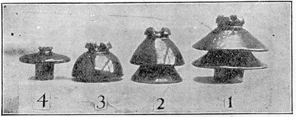
In no instance did a breakdown occur through the insulator itself, the break in every case being over the surface. The maximum testing voltage available was approximately 90,000 volts. In some instances, when the insulator was dry, no breakdown over the surface could be obtained. The following are the results of tests on certain characteristic insulators, as shown in the accompanying photographs. (Fig. 2 and Fig. 3).
No. 1Porcelain, brown glaze:
Diameter at base.......10"
Height.........8-¾"
Surface distance from wire to pin...... 22-3/4"
Shortest breaking distance. ............12"
When dry and clean, stood ....... 91,000 volts.
During heavy, dry-snow storm, stood........ 90,000 "
During moderate rain storm, broke down at ..... 86,400 "
When covered with ice and snow, broke down at......52,200 "
When dry, stood for hr......71,500 "
| |||
| Fig. 1. |

During the last test the snow was piled on the cross-arm almost to the lower petticoat.
No. 2Porcelain, brown glaze:
Diameter at base ......7-1/2"
Height ........6-3/4"
Surface distance from wire to pin ........13-1/2"
Shortest breaking distance........9-5/8"
When dry and clean, stood........92,000 volts
During dry-snow storm, broke down at........87,300 "
Covered with wet snow, broke down........62,100 "
During moderate rain storm, broke........68,400 "
When dry, stood for 1/2 hour ........66,000 "
No. 3Porcelain, brown glaze:
Diameter at base........6-3/4"
Height........4-7/8"
Surface distance from wire to pin.......13"
Shortest breaking distance.......7-1/4"
When dry and clean, stood .......91,000 volts
During dry-snow storm, broke down at......78,700 "
During moderate rain storm, broke down at.......48,600 "
Covered with wet snow, broke down at........54,000 "
When dry, stood for ½ hour........64,400 "
No. 4Porcelain, brown glaze:
Diameter at base........6-1/2"
Height........4-3/4"
Surface distance from wire to pin........8"
Shortest breaking distance........6-5/8"
When dry and clean, broke down at.......73,800 volts.
During dry-snow storm, broke down at.......78,850 "
During moderate rain storm, broke down at.......53,400 "
When covered with wet snow, broke down at .......52,350 "
When dry, stood for hour........55,000"
| |||
| Fig. 2. |
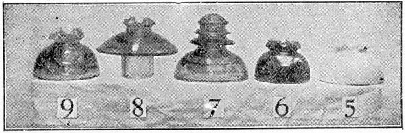
No. 5Porcelain, white glaze:
Diameter at base........6"
Height ........4"
Surface distance from wire to pin.......11-1/4"
Shortest breaking distance........6-1/4"
When dry and clean, broke down at .........74,700 volts.
During dry-snow storm, broke down at ........70,200 "
During moderate rain storm, broke down at ........ 70,400 "
When covered with wet snow, broke down at .......42,800 "
When dry, stood for 1/2 hour ....... 52,500 "
No. 7Glass:
Diameter at base ........ 7"
Height .......... 6"
Surface distance from wire to pin........15-1/2"
Shortest breaking distance........7-7/8"
When dry and clean, broke down at............74,700 volts
During dry-snow storm, broke down at........73,800 "
During moderate rain storm broke down at........52,800 "
When covered with wet snow, broke down at..........51,100 "
When dry, stood for 1 hour.............55,000 "
No. 8 Glass:
Diameter at base.....................7-1.2"
Height.................5-1/2"
Surface distance from wire to pin..............12"
Shortest breaking distance..............7-5/8"
When dry and clean, stood..............91,800 "
During dry-snow storm, broke down at...............87,300 "
During moderate rain storm, broke down at.............62,700 "
When covered with wet snow, broke down at.............58,800 "
When dry, stood for ½ hour................63,000 "
| |||
| Fig. 3. |
After the insulators had been up for some months and were well coated with dirt and soot they were given a time test on a dry day. The time test was made by applying of the maximum test voltage for hour. The figures are given under the last heading in each set of tests. All the insulators stood this test without any evidence of trouble, except a considerable static discharge over some of those with the thinner sections.
I think that the burning of pins is caused in many cases by the static discharges which appear at the wire and at the pin. If the material can be made thick enough, so that these discharges will not appear, the burning of the pins will probably be decreased to a very considerable extent. I think the final solution of the pin-burning question would be to discard the wooden pin altogether and substitute a metal pin properly cushioned to take undue local strains off the insulator itself.
Mr. Grace called attention to the trouble which the telephone companies have had from electrostatic effects. As fast as one difficulty has been overcome another is encountered, to overcome which new methods must be devised. The system of transposing wires in order to overcome the inductive effects of one circuit upon another was devised by the telephone engineers and first used on the long-distance circuit between New York and Philadelphia.
The necessity of keeping telephone circuits in absolute balance was mentioned and a number of instances were given where an extremely small amount of unbalancing was sufficient to produce serious disturbances.
Mr. Grace said that Mr. Lincoln's paper treated only of telephone circuits upon the same poles with the power circuit, whereas in commercial telephone service there were many thousands of circuits and it is manifestly impossible to insulate them to so high a degree as where there is but a single telephone circuit. He thought that representatives from the telegraph, telephone, and power-transmission companies should convene and devise suitable means for crossing the different lines where it is necessary.
Mr. Frankenfield commented on the effect of grounding the neutral point of a transmission system. He also commented on the burning of insulator pins.
Mr. Bedell recounted his experiences while testing insulators. His general conclusions were that the question of dielectric strength of glass and porcelain had been satisfactorily settled, as insulators almost never broke through the dielectric but over the surface.
MR. LINCOLN:One interesting statement made by Mr. Grace was that the arc circuits of the " tub system," so-called, is one of the hardest things the telephone people have to contend with. This sustains one of the arguments made in my discussionthat the static induction gives more trouble than the electromagnetic. The conductor in such an arc system is apt to be at a considerable difference of potential from the earth, and usually in the arc circuit the equal and opposite potential is not present to neutralize its effect as is the case with a statically balanced transmission line. I should imagine the arc circuit would be harder to contend with, though its potential is not so high as that of the usual accompanying transmission line. I should like to have Mr. Grace explain what he calls a retardation coil.
MR. GRACE:--It is an electric choke-coil and we speak of it as a retardation coil.
MR. ETHERIDGE:--I wish to refer particularly to the necessity of studying every detail of a transmission line, with the view of applying the latest and best possible forms of construction to insure the stability of the medium between the step-up and the distant step-down transformer.
Estimates are carefully prepared and the best engineering skill applied to the erection of central plants and substations, but the transmission line, which is subjected to the worst possible mechanical and electrical strains and conditions, is, generally speaking, the least considered and provided for.
The building of a transmission line is purely a mechanical problem, and must receive as much care and skill as the remainder of the system, if stability of actionwhich is the keynote of engineering successis to characterize its operation.
The average transmission line suffers from comparison with the modern power house and substation equipment, and as the system is strongest only at its weakest point greater care and skill must be applied to that part of the system which is found outside the buildings, where the most adverse mechanical and electrical conditions are encountered.
Our worst experience in the operation of transmission lines has been due to mechanical weakness of some of the details of the line; particularly wooden pins and faulty mechanical design of some of the insulators. The angles and guys have also given us trouble on account of their inadequacy for the heavy strains put upon them. I can safely say that electrical troubles of our line have been entirely absent. To overcome the mechanical troubles of pins and insulators, we were compelled to design and adopt a form of pin and insulator a sample of which you will find on exhibition here this evening, and in which the greatest mechanical strength and other features are embodied.
Having solved the question of weak pins and insulators, we next turned our attention to the angles of our line and to proper guying with the result of developing a rigid and successful form of construction. In these angles we have adopted poles of 13" and 14" tops, 4" X 5" double oak cross-arms with 3/4" ring bolts and washers. The braces are 3/8" X 1-1/2" and 30" long, bolted with 1/2" X 5/8" bolts and washers in cross-arms and through the poles, respectively. The cross-arms are bolted together with 5/8" bolts and washers with the usual making-up piece between them. The pin-holes in the cross-arms are 1-1/2" diameter, thereby maintaining the strength of the arm. Great care is also exercised in placing the arms diagonally across the angle so as equally to distribute the strain on each pin and insulator.
The "wet-rot" of our poles at the butt received our next attention, as it became evident to us that in seven to ten years our entire pole line would have to be rebuilt; a feat fraught with great danger, expense, and interruption in our service, if it did not threaten absolute shut-down.
I developed and adopted a remedy against this "wet-rot" of our poles. This consisted in cementing about one-third of the pole flush to and extending about 3" above the ground line, and then placing a fillet of pitch, asphaltum, or some such moisture-proof material to a depth of about 8" between the pole and cement of the ground-line, so as to separate or seal the pole from contact with the moisture in the earth at the ground-line. This very effectually prevents " wet-rot " of wooden poles and oxidation of steel poles at the ground-line. The additional expense of preparing and treating our poles in this manner is very trifling compared with the great expense of replacing them.
Mr. Scott has well said that "development of detail in electrical machinery has made possible very reliable forms of apparatus," and the same reasoning and skill must be applied to our transmission line before the ideal electrical transmission will be attained.
At the request of Mr. Lincoln I will explain the features of the pin and insulator which it was my pleasure to develop. It consists of a malleable iron tube 1-7/16" outside diameter and 1-1/8" inside diameter. On the outside of this tube-pin is cast a shoulder on which it rests when placed in the cross-arm. To lock this tube-pin to the cross-arm a flat high-carbon steel springon each end of which if formed a gibis driven through the pin until the bottom end springs out over the bottom end of the pin and cross-arm.
The insulator, which has a plain hole to receive the pin, and a recess at the bottom of the hole to receive the top gib of the spring, is then forced down over the pin until the top gib springs out into the recess in the insulator. This combination very securely locks the insulator to the pin and the pin to the cross-arm; to unlock, place a screw-driver between the lower gib and the pin, force the gib back and drive the spring out through the pin again.
The features of this form of pin and insulator are:
(1) Simplicity and durability.
(2) The presenting of a plain surface, so as equally to distribute the wire pressure between the contact or bearing surface of the pin and insulator.
(3) Secure locking to the cross-arm and ease of removal therefrom.
(4) Freedom of insulator to turn in either direction on pin and act as a sheave to the wire when used in angles.
(5) Looseness of the insulator on the pin, avoiding the breaking of insulators from expansion or contraction.
(6) Locking the insulator to the pin and cross-arm, yet preserving looseness and freedom on the pin.
(7) The placing of the wire groove in insulator so as to relieve the insulator from any wire leverage and any stress other than one tending to crush the glass or porcelain, etc.
Our telephone system is erected on the same poles and is bracketed about 5 feet below the lower cross-arm. These lines are absolutely quiet; the electromagnetic and electrostatic influence being overcome by using twisted pairs of wires.
(For illustrations of pins described by Mr. Etheridge, see New York Discussion, pages 26 to 57.)
MR. THOMAS:As Mr. Etheridge has said, the greatest practical difficulty in the operation of high-tension transmission lines arises from mechanical defects rather than electrical ones. Broken pins, broken cross-arms, broken insulators and injuries to the line from external causes vastly outnumber the electrical failures. As is easily seen, the pin is the weakest mechanical link of the system and when of wood of good insulating quality it is liable to be weak. I wish to call your attention to a plant installing at Mexico, which marks an improvement in pole-line construction from a mechanical point of view. Five hundred foot spans are used, which is approximately five times the length of span usually employed elsewhere, and instead of the usual wooden poles there are built-up steel towers. The cross-arms and pins, I understand, are of steel, the insulators of porcelain. This construction if well designed assures excellent mechanical qualities, and should be watched with great interest. On account of the small number of poles a much larger pin can be economically used for each one.
Ground wires, such as Mr. Lincoln has recommended for protecting the telephone circuit on a transmission line, might be used on telephone trunk lines, parallelling transmission lines, close to the telephone line but between it and the power line. It is probable that a very great reduction of the static induction from the high-tension would be obtained by the use of even a few grounded wires as a screen. I make this suggestion to Mr. Grace.
The question of lightning arresters for telephones, and the fact that they are ordinarily adjusted to discharge at about 300 volts, suggests the mention of a point in the operation on the telephone lines and power circuits by which in some cases the service has been very much improved. In a good many power transmission systems where the standard telephone' arrester is used on the telephone circuit, it has been found that there is at almost all times a sufficient unbalance of the high-tension voltage so that a frequent discharge to ground occurs over these arresters, the result being a leaky line and more or less continuous rattle of the telephone. The construction of an air gap in place of the lightning arrester very much reduces the number of such discharges to ground and entirely prevents the high resistance leak which usually occurs in a telephone arrester. The result is a great improvement in the speech.
Some of the telphone engineers here have referred to the problem of making satisfactory cross-overs between two lines. From their point of view the transmission line is a telephone line. The problem is broader, however, and should include the crossing of two high-tension lines. The National Board of Fire Underwriters has recently adopted recommendations as to methods of such cross-overs. They suggest three methods, but preference is expressed for crossing by means of a pole common to the two lines. This pole should, of course, have extra strength and extra height, the highest tension line being carried at the top. Extra long cross-arms are used and the difference in the height of the poles of the upper and lower lines will ordinarily prevent anything which falls from the upper wire to the ground from touching the lower wires. To prevent a wire breaking at the farther end of one of the adjacent spans of the higher line from falling against the lower line, a guard wire mounted on the line, preferably insulated, should be installed outside of the extreme wire of the lower line.
A wooden pin is burned by leakage current because either its resistance is too high to transmit the current without excessive heating, or because its insulation is too low to prevent the leakage. In most cases either a better or a worse pin would not be injured. A comparatively few per cent. improvement of the pin would in many cases be sufficient to prevent destructive heating. Therefore, the method used by Mr. Gerry for protecting the pin which has been put in first-class condition, from moisture and dirt, by means of a sleeve, is an excellent one, since it will certainly give a considerable protection to the pin and render it oftentimes safe where an unprotected pin will conduct enough to become charred. Mr. Gerry's freedom from trouble from burned pin referred to by Mr. Skinner is probably due to the fact that his pins are protected by glass sleeves, but also it must be admitted that his line is yet young and the climatic conditions are not severe. San Francisco is probably one of the hardest places in the country on pins and I think no wooden pins would be able to stand indefinitely there without burning.
Since the difficulty of operating a telephone line on an unbalanced high-tension power line results from the tendency for a high-potential to groundequally on both telephone wires, provided the telephone line be transposedit may be possible to solve the difficulty by insulating the telephone line highly and allowing it to assume its neutral potential, and transmitting the speech through a raising and lowering transformer at either end. The low-tension windings of these transformers may then be grounded, and with good insulation between the high and low-tension windings the operation may be made very secure.
I would like to ask Mr. Grace whether it is feasible to use such a transformer for transmitting telephonic speech.
The same sort of result might be attained by the use of condensers, two in series with middle grounded, connected between the wires of the insulated telephone line, the telephone receiver or transmitter being connected between the ground plates of the two condensers. For this purpose it would probably be necessary to use a double winding, either on telephone-spool or choke-coil, so that the charging current to the condensers would have its effect on the telephone circuit neutralized.
MR. GRACE:The use of the transformer, as suggested by Mr. Thomas, is feasible.
MR. PECK:In his paper on the testing of insulators, Mr. Blackwell says: "There should be but one transformer used to step up to the highest potential required and its reactance should be as low as possible. A number of transformers in series is particularly bad, as it gives poor regulation and leads to great uncertainty as to the actual potential to which an insulator is being subjected."
In the discussion at New York, Mr. Mershon called attention to the advantages obtained by the use of a number of transformers in series for obtaining a high voltage, saying that it was possible to obtain such a series having a good regulation; and great point in its favor was that in case of accident to one transformer of a series, the remaining transformers could be used to deliver a some what lower potential.
There is an idea more or less generally prevalent that it is possible to obtain without danger a high voltage by connecting in series a number of transformers wound and insulated for a low voltage, as long as cases are insulated from each other and from the ground. Fig. 1 shows such an arrangement, where three 10,000 volt transformers are connected with high-tension winding in series for giving 30,000 volts.
It will be at once seen that there is a strain of 30,000 volts at the two points (A) and (B). The normal strain for one transformer is 10,000 volts, so that the outside transformers of the series are subjected to three times normal voltage strain between primary and secondary windings. If there were ten 10,000 volt transformers connected in series for 100,000 volts, the strain across the outer transformers of the series would be 100,000 volts, ten times normal.
| |||
| Fig. 1. |
In the operation of a number of transformers in series for obtaining a high voltage, there are much more severe internal strains introduced than where the transformers are used for a 1ow voltage. This strain occurs between turns and lavers and comes principally on the outside coils of the outside transformers of the series. In designing transformers for connecting in series it is therefore necessary to insulate each transformer not only between high-tension and low-tension windings, but between turns and layers of each winding, in the same manner that would be required were the transformers to furnish alone the full voltage of the series.
On account of the large amount of insulating material demanded between high-tension and low-tension windings, it is extremely difficult to make these transformers with good regulation on inductive loads.
The cost of small transformers for very high-voltage work is, within certain almost independent of the capacity; so the difference in cost between one transformer of the series and a single transformer wound for the total capacity would be very small.
It is true that the outer transformers of a series may be more heavily insulated than the others, making a reduction in cost on the inside transformers, but this affects the interchangeability of the transformers and the extra cost of manufacturing transformers which differ slightly from each other will probably more than counterbalance the saving in insulation.
The question of a spare unit is undoubtedly of importance, but I believe that in general it will be cheaper to purchase two transformers, each wound for the full testing voltage, than to buy a large number of transformers which are to be connected in series for giving the desired voltage. Where two transformers, each wound for the full testing voltage, are purchased, one will of course be held as a spare and may be used as a voltmeter transformer for obtaining the exact voltage applied to the apparatus on test.
When a number of transformers are in series, the voltage measured across the high-tension winding of one transformer will not be an accurate indication of the total voltage on the series.
Mr. Rice called attention to the importance of uninterrupted service and to time tests on insulators. He predicted that the highest transmission voltage would very soon be generated directly by the dynamos, without the use of raising transformers. He also thought that the shoulder on the proposed pin was too small as the side strain would cause the shoulder to cut into the cross-arm, thus enlarging the hole so that the pin would finally pull out.
MR. SCOTT:I recall my first experiments on the relation between the telephone and a high voltage. In the laboratory a telephone was connected in circuit between a high-tension terminal and a short length of wire. It gave a vigorous sound which was attributed to the flow of current to the wire acting as a condenser. The wire was disconnected and the telephone still responded. The wire was then disconnected from the telephone circuit and was connected to the insulated magnet. The telephone still responded.
Some measurements upon the potential generated on an insulated wire not far from a high-tension circuit which were made by Mr. Tingley, who is here this evening, are reported in a paper on High-Voltage Transmission presented before the INSTITUTE by me in 1898. These experiments show that a single insulated wire not far from a high-tension wire may have a potential sufficient to cause a spark to jump over considerable gap to the earth.
I had an opportunity a few years ago to inspect the burning of pins and cross-arms on a 10,000 volt transmission line on the Pacific Coast, which ran for some distance close to the shore. Large holes were burned in some of the cross-arms and poles. The burning was particularly apt to occur at the ends of the iron braces between the pole and the cross-arm. There was little doubt but that particles of sea water as "fog" were carried by the wind and deposited salt upon the poles and cross-arms. I understand that this difficulty has been avoided by placing wooden frames over the insulators on the ocean side.
Mr. I. Sternefeld of Mexico has called my attention to the deterioration of copper wire due to the salt air from the ocean He says that he has found a satisfactory remedy in an insulated coating consisting simply of cotton dipped in a solution of minium and linseed oil.
It is notable that megohms, which used to be considered of prime importance in the testing of electrical apparatus, has not been mentioned in the discussion this evening. The problem in line construction is primarily to prevent disruptive and disastrous breakdown. It is not the ohms but the volts which are of first importance.
The collection of insulators before us this evening, containing some early forms as well as recent ones, small insulators as well as big ones, indicates the evolution which has taken place in insulator construction, both in materials and form during the last ten years.
The insulator problem, as presented in the discussion this evening, is at the present time primarily a mechanical problem. Electrically, it is partly one of materials and partly one of geometry. There is an intimate relation between geometry and voltage in insulator design. There is also the commercial problem.
High-tension tests upon apparatus, particularly transformers, is an important matter. The conditions prevailing at high voltages are to my mind different from those at lower voltages. Low-voltage apparatus may probably be tested at several times its operating pressure. The margin between the normal pressure and the test will be but a few thousand volts. If, however, transformers for 40,000 or 50,000 volts be tested at double pressure the margin is also 40,000 or 50,000 volts. The purpose of making a test of this kind is to determine first whether the design is satisfactory in giving sufficient surface distance and the like, and second to detect flaws in material (3,1. in construction. A momentary or short test is in general sufficient to determine these points. The prolonged test may have a deleterious effect upon the insulating materials by weakening them. The test may result in a breakdown due to conditions entirely abnormal to service. On the other hand, although there may be no breakdown the materials may be left in a condition weaker than they would have been if the test had not been prolonged.
MR. BUDD FRANKENFIELD:Speaking of the dependence of transmission systems on the telephone in time of emergency, recalls an incident that came under my observation on the coast. It belongs in the category with the somewhat disastrous accidents that sometimes occur when too great reliance is placed on automatic devices.
A fire occurred in a city that received power from a long-distance transmission system. The fire caused havoc in the secondary network, and the substation attendant pulled all his switches in the emergency, without first notifying the power house. At the power house the governors happened to be off duty and the impulse wheels took on speed. Instead of taking recourse to the "Armstrong system" and shutting down the plant as he might have done, the power station attendant ran to his telephone booth to call up the substation.
He never got into communication; for there was a crash which brought him out of the booth to gaze in open-eyed wonder at the roof abovethe fly wheel had gone soaring heavenward and it left a great hole in its wake. Here is an instance where it had become so natural to use the telephone in every emergency that, what is ordinarily a blessing, proved a source of danger. The moral is to use "horse sense" even when surrounded by modern conveniences.
In regard to the suggestion that the ground be brought near the telephone line by means of an earthed conductor placed in proximity, I would like to recall the fact that grounding the neutral of a Y. connected transformer system has this effect, as stated in the paper, that the telephone line tends to assume the potential of the neutral point of the transmission system; and the grounding of this point will virtually bring the telephone line to the potential of the earth. It seems to me a method worthy of careful consideration.
It has been suggested that by using an iron insulator pin burning would be avoided because of the low resistance of the pin; and it has been urged in opposition, that the wooden pin bas some give to it and is less likely to break insulators. Why not combine all the good qualities in one pin, a wooden pin with a metallic coating? Cover it with foil, paint it with a metallic paint, electroplate it if need bedo anything to make it a good conductor. A study of the Redlands type of pin, which is said to have shown deterioration only at the wooden thread and which is said to have caused no burning of cross-arms, is an indication of the result to be expected with a metal-coated pinno burning at all.
