[Trade Journal]
Publication: Electrical Review
New York, NY, United States
vol. 29, no. 21, p. 247-249, col. 1-3
NIAGARA FALLS POWER IN BUFFALO.
A Successful Test at Midnight, Sunday, in the Presence of the Officials.
ONE THOUSAND HORSE-POWER TRANSMITTED FROM THE NIAGARA FALLS POWER COMPANY'S GENERATORS TO THE BUFFALO RAILWAY COMPANY'S NIAGARA STREET STATION - A DESCRIPTION OF THE TRANSMISSION LINE AND ITS CONSTRUCTION - THE FIRST CURRENT SENT OVER THE LINE AT 8:57 O'CLOCK SUNDAY NIGHT, NOVEMBER 15 - ONE MINUTE AFTER MIDNIGHT POWER WAS DELIVERED AT BUFFALO AS AGREED - EVENT CELEBRATED WITH FIRING OF CANNON - MAYOR JEWETT AND ELECTRICAL OFFICIALS PRESENT.
[Special Dispatch to the ELECTRICAL REVIEW.]
BUFFALO, N. Y., November 15, 1896 - When the Buffalo Railway Company some time ago made a contract for the delivery of 1,000 horse-power of electric current from the great plant at Niagara Falls, and this fact was announced, there were many skeptics who observed that it was not quite time to cancel orders for coal. The contract specified that 1,000 horse-power of current should be transmitted from the Falls to the Niagara street power house of the Buffalo Railway Company on or before November 15, 1896.
As the result of some unusually intelligent and rapid construction work on the part of the White-Crosby Company, of New York city, and in spite of certain apparatus required on the line, the contract has been fulfilled in all requirements, and it only remains for the officers of the Cataract Power and Conduit Company and the Buffalo Railway Company to decide when to turn the current on the line.
This will probably be done some time to-night. It is hoped and expected that everything will go off as smoothly as the launching of a ship, but it is deemed advisable to have one section of the Buffalo Railway Company's lines in readiness to receive current from the Falls alone, so that a more exact idea may be obtained as to how everything connected with the transmission of current will work. This can be best accomplished during the night hours.
| |||
| Fig. 1. A View of the Buffalo-Niagara Falls Electric Transmission Line, Showing Method of Turning Corners. the Capacity of This Line is 20,000 Horse-Power. (See "Niagara Falls Power in Buffalo.") |
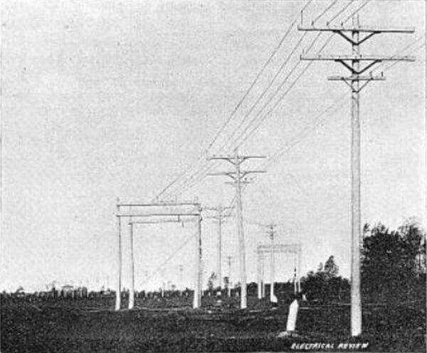
The transmission line is 26 miles long and extends from the rear of the Niagara Falls Power Company's transformer house at the Falls to the Niagara street power house of the Buffalo Railway Company. The exact route of the line is as follows:
Northerly side of Adams avenue on the power company's property to a point one and one-half mile east of Sugar street, where it leaves Adams avenue and runs along the west side of the Niagara Junction Railway to a point one mile north of La Salle. From this point it runs along the old Mile Line survey to Tonawanda Creek. It crosses Tonawanda Creek near Division street in Tonawanda and then passes southerly across the lands of the Buffalo, Thousand Islands & Portland Railroad to Ellicott Creek, which it crosses. Then it continues south to the southerly line of the village of Tonawanda. From this point it runs west for a mile and a quarter, where it strikes the east bank of the Erie Canal near Hinds street in the village of Tonawanda. From this point the line extends along the banks of the canal all the way to Buffalo.
A description of the line and the work involved in its construction may perhaps be more readily understood if the course of the current from the big generators at Niagara Falls to the railway power house is followed. A three-phase alternating current of 2,200 volts is carried from one of the big generators through a cable across the "Bridge of Sighs" to an air-tight chamber in the transformer house. These cables are here connected to two step-up transformers of 1,250 horse-power each, which transform the current up to 11,000 volts. The cables carrying this voltage are led to a marble switchboard situated near the transformers and provided with immense knife switches and fuses, whence the circuit passes to the pole line which begins immediately in the rear of the building.
This pole line is a work of art beside being an engineering feat of importance and magnitude. Many novel features are incorporated in its construction, which will no doubt be used with advantage in the construction of similar lines. The White-Crosby Company, to whose hands this important work was entrusted, were practically allowed carte blanche in the matter of expense, as the desire of the projectors of the line was that it should be of the very best construction and material, irrespective of cost.
Owing to the peculiar circumstances encountered in securing the right of way for the line, it was not possible to build it in a straight line, as would have been desirable. It followed, therefore, that a considerable number of angles and turns had to be provided for. That this has been done in a novel and most substantial manner will be apparent from the various illustrations shown herewith.
There are about 2,100 poles in the line, ranging from 35 to 65 feet in height, from 15 to 30 inches in diameter at the base, and from 9 to 10 inches in diameter at the tops, set about 75 feet apart. They are of round cedar, shaved and painted. When the line is finished the color of the poles will be dark green. There are two large cross-arms provided for carrying the transmission line proper. These arms are of hard yellow heart pine, 4 by 6 inches by 12 feet, dressed, chamfered and painted. A radical departure in the bracing of these cross-arms has been designed by the White-Crosby Company. Instead of the usual flat iron braces attached to the pole and arm by lag bolts, a brace made of one piece of angle iron is used. As shown in the accompanying drawing, Fig. 3, this brace is fastened to the pole with one lag bolt. It is attached to the lower surface of the cross-arm, instead of on one side, as usual. It will be seen that such a brace, attached in the manner described, at once acts as a truss. Each brace weighs about 20 pounds, and is made of two and one-half by one quarter-inch angle iron, formed hot and bored for lag bolts. The braces were made by the Cambria Iron Company, of Johnstown, Pa.
Below the two large cross-arms is a standard six-pin electric light arm bored for two pins. This is to carry a private metallic telephone line, which is now in process of construction. The smaller cross-arm is braced in the ordinary manner with flat irons. The drawing referred to before affords a good comparison of the two methods of bracing.
The pins shown on the extremities of the lower, long cross-arm are steel guards, to prevent any of the conductors from falling in case a tie-wire, pin or insulator breaks. The long steel pins on the top cross-arm are for a similar purpose, and also to carry the wire which will be used as a lightning conductor. Another conductor of the same kind is carried on top of the poles. At every fifth pole these lightning conductors are grounded to a coil of wire buried at the foot of the pole.
When the entire line is completed, it will have a capacity of 20,000 horse-power. As it is a three-phase line, each circuit will be composed of three conductors carrying 5,000 horse-power, or four circuits in all. To overcome the effects of induction, the various circuits composing the line are transposed from pole to pole. When the line is finished to its full capacity, the phase of this transportation will be such that the entire line will be shifted on five poles. The overhead portion of the line will be fenced in throughout its length.
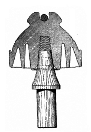 |
| Fig. 2. Type of Specially Designed Porcelain Insulator Used on Buffalo-Niagara Falls Electric Transmission Line. |
A most important feature of this line is the special type of porcelain insulators used. These were designed especially for this work by the White-Crosby Company, and have been manufactured by three separate concerns. The illustration, Fig. 2, shows one of these insulators attached to a cross-arm pin. The insulators are of the triple petticoat type, with uniform strength. The design is so proportioned as to protect all weak points. Along the lower edge of the outside petticoat is a gutter designed to drain away water on each side of the cross-arm. The construction is such that icicles are compelled to form at but two points, both clear of the cross-arm.
Before being accepted for use on the line, the insulators used were subjected to an unusually rigorous test under the supervision of Mr. Paul M. Lincoln, electrical superintendent for the Niagara Falls Power Company. The tests were made to determine both the electrical resistance and to discover any possible mechanical defects in each individual piece. The method of testing was about as follows: The insulators were immersed in a salt water bath and a current of 40,000 volts form a transformer covered with oil was passed through each piece. It was found, after many experiments with both fresh water and salt water baths, that a great gain in the speed of making the tests was secured by using slat water. At the slightest sign of a defect of any kind, the insulator showing it was at once condemned. Although such a test may appear unusually severe for insulators designed to carry a circuit transmitting but 10,000 volts, it was deemed to be the wisest course to pursue, as it assured a large factor of safety.
As mentioned before, these porcelain insulators, which, by-the-way, weigh nearly 12 pounds apiece, were made by three separate concerns. It is but just to state that those manufactured by the Imperial Porcelain Works, of Trenton, N. J., passed the severe test with an unusually high record. Less than two-thirds of one per cent of one pattern of the insulators supplied by this firm failed to stand the test.
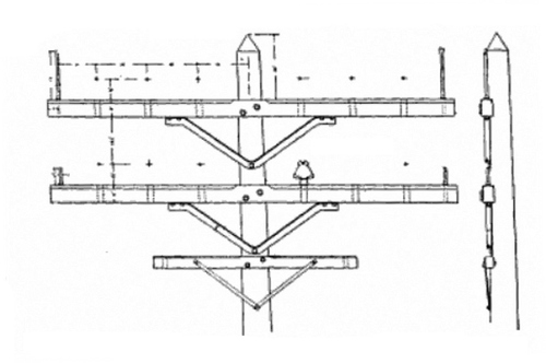 |
| Fig. 3. Top of Pole and Pole Fixtures Used on the Buffalo-Niagara Falls Electric Transmission Line. |
The overhead conductors used on the line are bare stranded copper, each 350,000 circular mils in diameter. Each conductor is formed of 19 No. 10 wires. For the present demands of the transmission line the American Electrical Works, of Providence, R. I., has supplied 66 miles of the bare conductors just described. The facilities which this concern has for turning out large orders for heavy wire enable it to produce a product uniform in all respects, both mechanically and electrically.
When the line is completed to its full capacity, each pole will carry a weight of 1,200 pounds of copper. The mechanical strains to which the poles and line may be subjected have been determined with great exactness. These calculations have been carried to the extend of assuming the whole line to be covered with one-half inch of ice. The staunchness of the line may be inferred when it is stated that when the writer inspected it to-day there was a wind of at least 40 miles an hour blowing across the line. Not the slightest tremor in a single pole could be discovered, and the vibrations of the three overhead conductors were barely visible. The only effect of this high wind was to produce the Aeolian sighing common to telephone and telegraph lines.
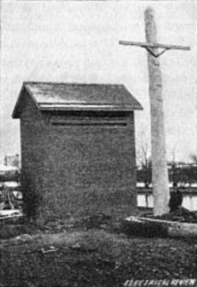
For a considerable part of its length the transmission line follows the bank of the Erie Canal. At a point about 4,200 feet north of the Buffalo Railway Company's power house the overhead line stops, and from there to its end the line is carried under ground. The last pole on the line is about 35 feet high and 30 inches in diameter at the base. It is set in a bed of concrete about five feet in diameter and 10 feet deep. This pole is also heavily braced from the north, and the ends of the line are held firmly in place by double cross-arms with braces between them. The line descends from the pole in a slight curve and enters a neat brick terminal house at an upward slant through a slit in side of the house. Inside the house connections are made with the underground cables.
The subway carrying these cables is also laid along the bank of the canal at an average depth of about one and one-half foot. The subway is constructed of vitrified tile ducts, each having a single hole three inches in diameter. The subway is built up of 12 of these ducts laid in cement, with the joints suitably broken. There is at least four inches of concrete on all sides of the subway. There is at least four inches of concrete on all sides of the subway. With 12 ducts, the capacity of the subway is the same as that of the overhead line. After the whole 4,200 feet of subway had been laid, it was thoroughly inspected, and it was found that not a single tile had been broken in the course of construction. In only two places was it necessary to file out cement which had seeped through the joints. The tiles were made by the H. B. Camp Company, of Aultman, Ohio. There are 16 manholes along the line of the subway. They are octagonal in form, with an interior diameter of about five feet. The bottom is formed of six inches of concrete and one layer of brick, and the sides are brick walls one foot thick.
The three lines of cable now laid in the subway consist of a stranded copper core, 350,000 circular mils in diameter, covered with 9-16 of an inch pure rubber, two servings of rubber tape and a coating of lead. The diameter of the cable over all is one inch and a half. There are about 13,000 feet of cable now in the subway, all of which was furnished by the Safety Insulated Wire and Cable Company, of New York city, under rigid guarantees. The tests of this cable were made at Niagara Falls by Mr. Paul M. Lincoln, and it may be interesting to know that the cable in all cases successfully withstood a current of 40,000 volts, alternating. The method of making these tests permitted it to be positively known that at least 40,000 volts had no effect on the insulation. Mr. Lincoln carried the tests to an extreme, and finally succeeded in forming an arc between the lead covering and the core of the cable at a voltage which he estimates as between 80,000 and 100,000 volts.
| |||
| Fig. 4. Buffalo-Niagara Falls Line Terminal House Where Under-Ground Cables Begin Pole 30 Inches in Diameter. |
The underground cables, as stated before, are carried 4,200 feet along the canal bank to a transformer house which has been built in the rear of the Niagara street power house of the Buffalo Railway Company. This is a one-story brick structure whose inside dimensions are 16 by 20 feet. At the rear of this room is a marble switchboard similar in character to the one at the Falls end of the line and similarly equipped. The cables are carried in the conduit under ground clear up to the switchboard. In the center of the room is an air-tight platform on which the three step-down transformers stand. All the transformers were supplied by the General Electric Company. This room is equipped with a blower operated by an electric motor similar in character to the outfit at the Falls end of the line. The object of the blower is to drive a current of air inside the air-tight platform, whence it ascends through and around the transformers, thus helping to keep them cool. The lines are carried from the switchboard to the transformers and from them to the rotary converters located on the floor of the power house above. Each of these transformers is of 265 kilowatts capacity, and steps the current down from 10,700 volts to 370 volts. After these 370 volts of alternating current have passed through the rotary converters, it becomes 550 volts direct current, and is ready to send out over the electric railway lines. This, in brief, describes the various changes through which current generated at Niagara Falls passes before it is used to operate street cars in Buffalo, 26 miles away.
| |||
| Fig. 5. Buffalo-Niagara Falls Line Where Line Enters Power House, Niagara Falls, N. Y. |
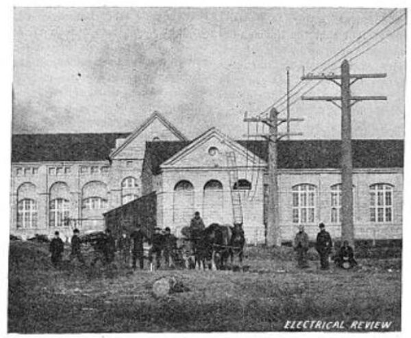
This transmission line has been built by the White-Crosby Company, of New York city, for the Cataract Construction Company, of which Mr. William A. Brackenridge is chief engineer. Mr. Brackenridge has been in charge of the construction work of the line on behalf of his company, and it was under his direction that the transformer house of the Niagara Falls Power Company was fitted for its part in the work described. When the line is completed, the Cataract Construction Company will turn it over to the Niagara Falls Power Company, whose final property it becomes.
The Niagara Falls Power Company will generate the current at the Falls and send it over the line to the city limits of Buffalo. Here it will be delivered to a sub-company of the Niagara Falls Power Company, known as the Cataract Power and Conduit Company. The latter is the distributing company in Buffalo. Its president is Mr. George Urban, Jr., and Mr. George R. Huntley is its vice-president and general manager. The capital of the company is $2,000,000, and its board of directors is as follows: E. D. Adams, John Jacob Astor, D. O. Mills, Daniel O'Day, William B. Rankine, Francis L. Stetson and Edward L. Wickes, of New York, and Charles R. Huntley and George Urban, Jr., of Buffalo.
The intense interest taken in the construction and successful opening of this line has been very marked in Buffalo and surrounding cities and towns. A large number of engineers, both electrical and mechanical, have visited the work during its progress and have expressed themselves as greatly surprised and pleased at the extent of the work and at the splendid ability shown in the designing and building of the line. There are thousands of men in the city of Buffalo who believe that the successful transmission of Niagara power to that city will be a most important factor in its future growth and prosperity. It is expected that this current will be sold within the city limits of Buffalo at a price below $40 per horse-power per annum. With such advantages as electric power offers, and with the civic enterprise and spirit which is a characteristic of Buffalo business men, it is expected that the growth of the city, at least on its manufacturing side, will from now on be very rapid.
A number of these gentlemen, prominent among them Messrs. George Urban, Jr., and Charles R. Huntley, are arranging to have a fitting celebration of the the transmission of Niagara power to Buffalo at some future date, probably during the holidays. The exact time has not finally been decided upon.
As is well known, some of the most enterprising and far-seeing business men of the State, and some of the most able engineers, are connected with the Cataract Construction Company and the Niagara Falls Power Company. What their plans may be for the future extension of transmission lines from Niagara Falls to the surrounding cities and towns can not be ascertained, as they prefer to do their work in a quiet manner, without the help or advise of the public at large. It is safe to presume, however, that the line just completed is but the first of several which are yet to be built. The work on the extensive addition to the Niagara Falls Power Company's plant is well under way. When it is completed the plant will probably have sufficient capacity to supply all demands in the immediate vicinity of Niagara Falls, and enough to spare for any enterprising town or village within a reasonable radius which may apply for it. In the successful construction and operation of the line just opened, a splendid beginning toward this end has been made.
STEPHEN L. COLES.
