[Trade Journal]
Publication: Cassier's Magazine
New York, NY, United States
vol. 27, no. 3, p. 171-200, col. 1-2
PIONEER WORK IN HIGH - TENSION ELECTRIC POWER TRANSMISSION
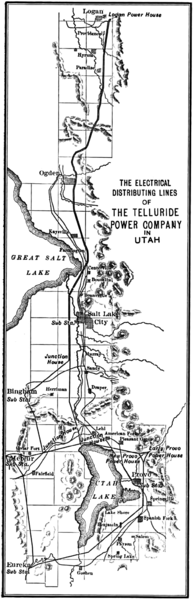
THE OPERATIONS OF THE TELLURIDE POWER COMPANY
By P. N. Nunn
In the light of present achievements in high-tension, long- distance electric power transmission, the early work of the Telluride Power Company, fourteen years ago, and further developed in the immediately succeeding years, commands unqualified admiration. It was work of daring enterprise, pioneer work in the face of discouraging comment from almost everywhere, making its successful outcome all the more gratifying to those who undertook it, and interesting to the profession generally. Mr. Nunn's account of it was given for the first time in a paper presented at the recent International Electrical Congress at St. Louis, and its publication here, embellished by many additional illustrations, has been made possible through his kind co-operation. The Editor.
DURING the winter of 1890, the year preceding the famous Frankfort-Lauffen experiment, apparatus was installed for the first commercial, high-pressure, alternating-current power transmission of the world. From that beginning has grown the Telluride Power Company.
The mining district surrounding Telluride, Colorado, is at the same time one of the most rugged and one of the richest in the Rocky Mountains; but its inaccessibility and the consequent cost of producing power caused the financial failure of many important enterprises in the early days of its history. The statement made in the annual report of the Treasury of the United States, in 1901, that "for the growth of its mining industry San Miguel County is indebted to the Telluride Power Transmission Company more than to any other agency," is borne out by the fact that at the present time all the important mines and mills of the district are operated by power furnished by this company.
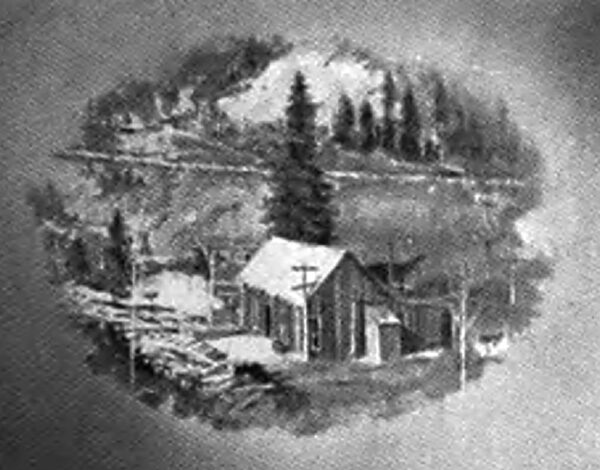
| |||
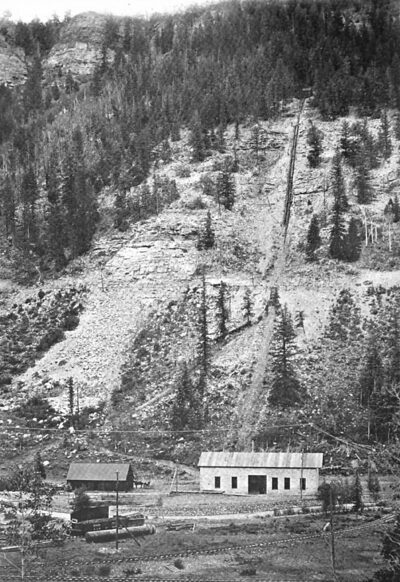
| The Original Power House at Ames, 1890 |
The Gold King mill, situated at an altitude of 12,000 feet, where the cost of fuel for steam power had become prohibitive, was the first to be operated by means of this power. This property had been attached in 1888 to satisfy a continued deficit in operations. Mr. L. L. Nunn, the attorney retained by the owners, found that this deficit was due largely to the enormous cost of power, and that there would have been a handsome margin if power could have been furnished at not more than $100 per H. P.-year. Down in a deep gorge of the valley, over 2000 feet lower, but less than three miles away, two mountain streams formed at their confluence the South Fork of the San Miguel River, offering cheap and continuous power.
A stay of proceedings was secured, and, as a means of transmitting this power, cable drive, compressed air, and continuous-current electricity were all investigated. The limitations of each were apparent, while the advantages of alternating current and higher pressures became gradually recognised, and a decision was reached to attempt their use. This decision was due less to the immediate saving in copper than to a keen sense of the limitation of continuous, and faith in the final success and ultimate superiority of, alternating current.
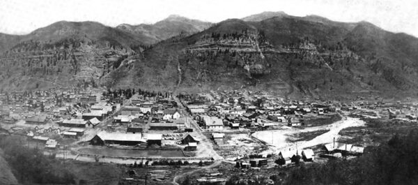
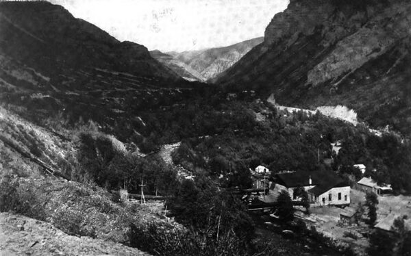
| |||
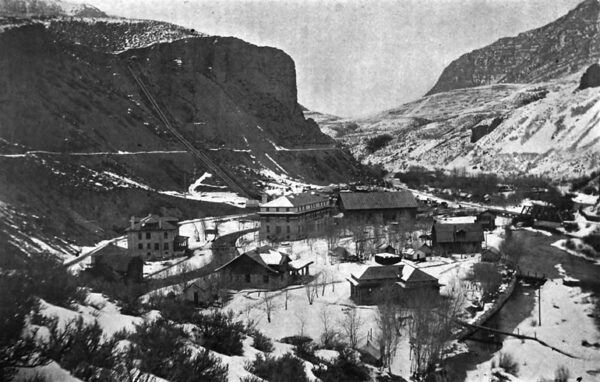
| A View of Telluride, Colorado |
During the investigation which followed, while selecting apparatus, little but incredulity or ridicule was encountered. Eastern investors in the enterprise were annoyed by predictions of prominent engineers, and discouraged by their insistence, that the experiment would prove a miserable failure and the expenditure go for naught. It was said that there was no alternating-current motor; that oil insulators must be used, and that the line must be fenced in. However, a generator and a motor for 3000 volts and of 100 horse each were ready for trial in the fall of 1890.
Difficulties caused by ice at 40 degrees below zero, by speed control over unusually high water pressure, by avalanche, by blizzard, by electric storms unknown in low altitudes, and scores of others, now generally forgotten, but then most serious, marked every step of progress. Notwithstanding all of these, unqualified success from the beginning caused gradual and constant growth, until at the present time the Telluride Company and its allied industries have six power stations and nearly a thousand miles of line in Colorado, Utah, and Montana.
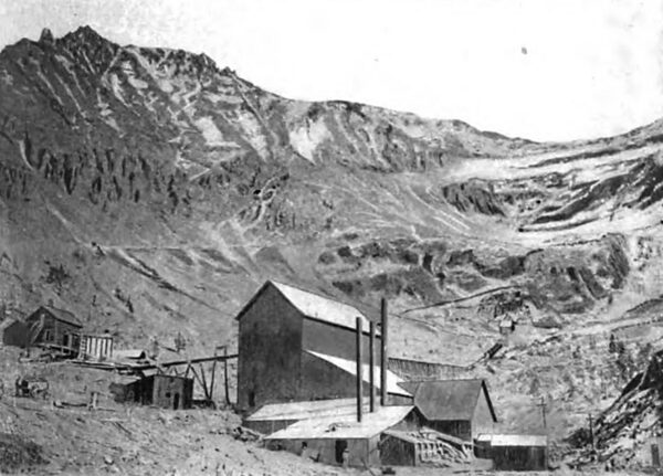
| |||
| Gold King Mill, in Which the First Synchronous Motor Was Used |
Following its pioneer power transmission, it made practical experiments as early as 1895 with pressures which have never, even yet, been exceeded, and for three years it operated commercially the highest pressure transmission of the world. Thus the record of its work becomes an important chapter in the history of power transmission; but it must readily be seen that the limit of this paper precludes the possibility of describing, even in the briefest terms, all, or even a substantial part, of its pioneer work.
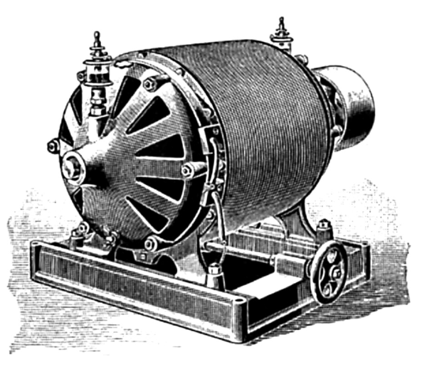
The initial installation, purchased through Mr. F. B. H. Paine, comprised a generator installed in a rough cabin upon the site of the present Ames station and belted to a 6-foot Pelton wheel un-der 320 feet head, and a motor at the mill 2.6 miles distant. The two were identical Westinghouse single-phase alternators of 100 H. P., the largest then made. The generator was separately excited, while the motor was self-exciting. Each carried a twelve-part commutator, and was slightly compounded through current transformers Upon opposite spokes of its armature. The latter were ironclad, or "T" - toothed, wound with twelve simple coils in cells of fullerboard and mica. Switchboards consisted of matched and shellaced pine sheathing. and the bases of instruments were dry hardwood. Only voltmeters and ammeters were used, both of the solenoid and gravity balance type, in black walnut cases with window glass fronts. Circuits were closed with jaw switches and opened by arc-light plugs. The line carried two No. 3 bare copper wires, mounted upon short Western Union cross-arms and insulators. The copper cost about $700, or about 1 per cent. of the estimated cost for continuous current. The main motor was brought to synchronous speed by a single-phase induction starting motor, which received its current at full line voltage. The current taken was more than full load current of the main motor. This starting motor even required starting by hand, its torque being zero at starting, and so feeble at low speeds that when cold it could only with the greatest difficulty be persuaded to pull up to speed its belt and loose pulley. Nor could it at speed start the main motor without help, and even then it became so hot that its short-circuited secondary frequently burned out.
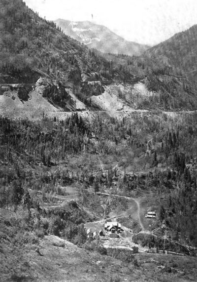
| |||
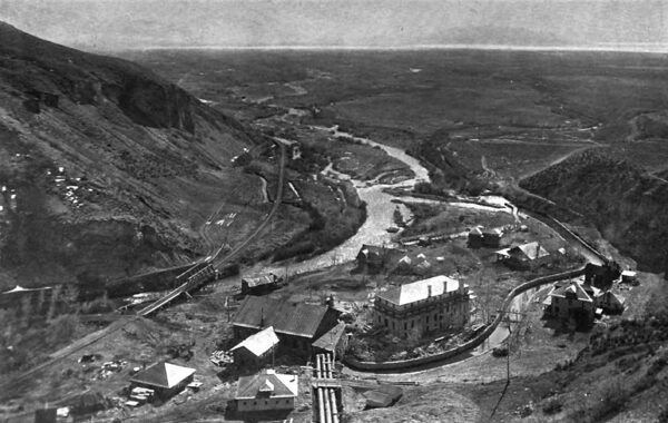
| General View Showing Ames Water Power and Its Location |
Another motor of 50 horse-power was soon added. While in other respects similar to the first, this motor was intended to be self-starting, with armature and field in series through a current transformer, and on account of its frightful flashing it was fitted with a special eight-part commutator of non-arcing metal. This feature, however, proving a failure, was soon replaced by a separate starter.
The need of wattmeter or power- factor indicator not having been at that time recognised, motor field charge was adjusted for least main current. This current was accepted as having unity power factor, and, therefore, as the measure of actual power.
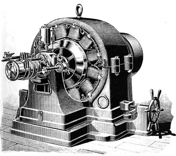 |
| The Earliest Alternating Current Generator for Power Service |
Everything was extremely simple, from water-wheels to motors, and, except for lightning, the plant ran smoothly and steadily thirty days and more without a stop. The report made in the East by associates of the enterprise that at Telluride a hundred horse-power were being successfully transmitted nearly three miles over No. 3 copper, with less than 5 per cent. loss, was received with the utmost incredulity.
During the autumn of 1892 a 600-horse generator of the same characteristics was installed, and a 250-horse motor for the mill on Bear Creek, ten miles from the generator. Early in 1894 a 50-horse, and, during the fall, a 75-horse motor were placed in Savage Basin, fourteen miles from the power house. The former was soon replaced by a 100-horse motor, and in 1895 a 100-horse motor was set up at Pandora.
Except as to size, these motors were substantially identical. The 250-horse motor was badly designed, and the pole pieces were of cast iron. Its starting motor was insufficient, and was, therefore, soon replaced by one having split-phase secondary with external resistances. Marble with brass trimmings replaced wooden-base instruments, and such elegance demanded highly polished slat switchboards of paraffined oak. Imposing marble rheostats were mounted at switchboards like keyboards upon grand organs. Fuse blocks, the only protective device, became marble slabs with duplicate aluminium strips. The first synchrophone came with the 75 H. P. equipment.
"Owing to its altitude and geographic position, the Telluride district is peculiarly subject to atmospheric disturbances. Over a hundred distinct discharges have been counted within a single hour, and lightning caused more discouragement than any other obstacle.
A neighbouring continuous current plant, transmitting a little more than a mile, carried several extra armatures; and even then it was so frequently compelled to close down during the daily storms of the rainy season that the company was eventually bankrupted.
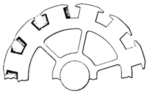 |
| Section of "T"-Toothed Armature With Three Coils in Place |
The alternating plant might have suffered a similar fate had it not been for its "T"-toothed armatures and replaceable coils, eight of which were successively burned out and replaced on one motor within a single week. To get a coil into place, and its oak keys driven home, required such bending, clamping and pounding as inevitably resulted in injury to insulation, and only by the greatest care could replaced coils be made to stand a test adequate to the 3000 volts employed.
For protection from lightning several types of manufactured arresters, then various original devices were tried, ending with a simple gap in series with a score or more of fuse blocks in parallel, arranged about a radial commutator switch, turned from point to point as the fuses were blown by successive discharges. From the first, these conditions caused the greatest apprehension as to the commercial success of electric power transmission, until Mr. Alexander J. Wurts, during a stay of several months with the company, gave the protection of the now well-known non-arcing arrester.
No transformers were used between machines and line, the largest transformers at first being 2 KW, or 40-light. Aside from the effects of lightning, even to-day 3000 volts upon the winding of small, high-speed armatures requires first-class insulation. Frequent grounds were prevented by deep insulating foundations of paraffined wood. To prevent short circuits within the coils, their cells, just before placing, were poured full of shellac, and the entire armature was afterwards baked for several days. By this means the 50-horse motor ran a full year without trouble in a room dripping with moisture.
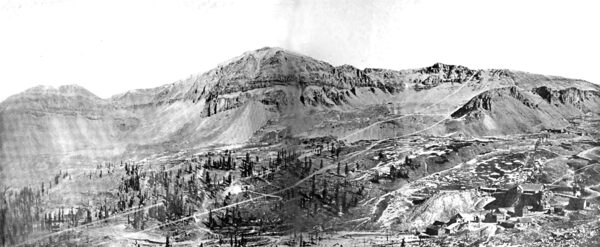
| |||
| General View of Savage Basin, Showing the Tomboy, Japan and Other Properties and Camp Bird Divide |
A lighting transformer received in 1891 was rated at 5 KW. Thereto-fore transformers had been rated in lights, 'and generators in horse-power. This transformer was immersed in engine oil, and marked an epoch in the company's history. Lightning frequently punctured it, causing its fuses to blow without other apparent injury. It remained in service for years. All others were soon likewise immersed. Four 500-light, dry Stanley transformers, purchased in 1892 for lighting Telluride, were broken down by the thunder storms of the following spring. When repaired, these also were immersed in engine oil, and gave no further trouble during the three years they remained in service.
Alternators were paralleled at Telluride in the spring of 1893, and thereafter they were so operated with full load upon the smaller and regulation upon the larger machine.
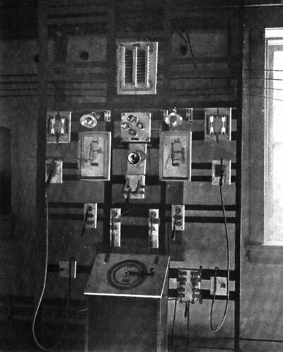
Manipulation at switchboards or at brushes involved direct handling of 3000 volts,a rather high switchboard pressure even now. It was a rule that every attendant keep one hand in his pocket while working with the other. 1t is pleasant to record that during these years no loss of life and but few accidents occurred.
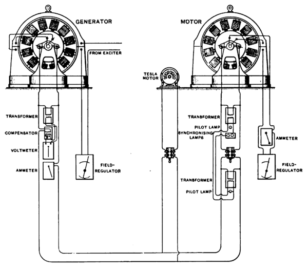 |
| Diagram of Original Synchronous Motor System at Telluride |
There being no other circuit breakers, it was necessary when a motor dropped out of step to break the circuit with the single arc-light plug. This always drew a heavy, vicious arc, which, on the big motor, frequently held to the full length of the 6-foot cable, and then sometimes required a whiff from the attendant's hat. When not broken promptly, it frequently involved the entire switchboard and shut down the plant.
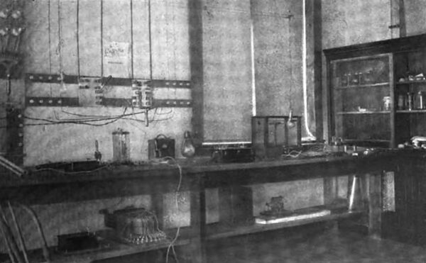
Duties of_ this nature required considerable skill and cool heads, and in order to operate the plant continuously, night and day, fifteen or twenty competent attendants were required. To fit young men for these positions, a course was arranged during which they were taught something of machinery, of shop-work in metal and wood, and of wiring, insulating and repairing, while receiving such assistance in daily study as conditions permitted. A technical library, including the electrical papers, and a conveniently fitted testing room were always open. Each student was then given a short laboratory course in graphic treatment of alternating-current theory. This is said to have been the first systematic effort made by a corporation to train its employees for responsible positions.
 |
| Tesla Starting Motor |
Although the plant, as a whole, was an unqualified commercial success, no explanation need here be made as to why it was replaced by the induction system as soon as the latter had been perfected. This marks the limit of the most extensive single-phase, synchronous plant ever operated. With but one or two motors its operation was not difficult, but each motor added to the system brought increased demand for care and skill.
The causes of difficulty were not understood then as now, nor was the effect of power factor fully appreciated. Lack of both wattmeters and power-factor indicators left the adjustment of field charges to the judgment of the operators. The power factor of each motor being dependent not only upon its own adjustment, but upon that of all, the closest attention and co-operation were necessary, in marked contrast with the simplicity of operation of induction motors. Disturbances due to starting motors were especially trying; and the unqualified success attained, notwithstanding defects of apparatus and system, is attributed now, far more than then, to the skill and vigilance of the operators in this new and fascinating field.
| |||
| The Early Laboratory for Students |
The Tesla system, substituted for the synchronous in the year 1896, comprised two 600-KW, 60-cycle, 500-volt, two-phase generators, direct connected to water-wheels under 600 and 900 feet head, respectively, and an equal capacity of raising and reducing transformers and of two-phase, 220-volt induction motors. The twelve Too-KW step-up transformers were connected in pairs, two-phase, three-phase for three phase, 10,000-volt transmission. These transformers were worthless; all broke down within a year, and one or more were always undergoing repairs. Breakdowns occasionally caused sufficient explosion to lift a cover, or splash the oil. The woodwork soon became saturated, and hot metal from the near-by main fuses frequently started fires, endangering the wooden power house. A masonry transformer house in two compartments was, therefore, constructed, and into it the transformers were moved,this being the first known case of isolation of oil transformers on account of fire risk.
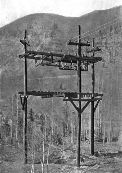
The power house at Ilium, situated six miles below Ames, on the same stream and using the same water, was built in 1900, and contains one 1200-kilowatt, revolving-field, General Electric generator, direct connected to two impulse wheels under 500 feet head. Transmission lines extend both to the Ames station and to points of distribution, providing the insurance of duplicate transmission. Any section of line can be cut out for repair, or either power house shut down, without interrupting the service. Junctions other than generating and distributing points. are equipped with open air switches, mounted upon standard line insulators. and operated from platforms similarly insulated, and have proven invaluable.
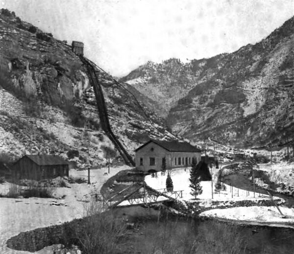
| |||
| The Ilium Power House |
Junction houses at distributing centres provide for a branch line to each customer, which is equipped with switches, fuses, and a set of five record-making instruments,a voltmeter, two ammeters and two wattmeters. The power company thus secures upon its own property a continuous, accurate, and satisfactory record of each load.
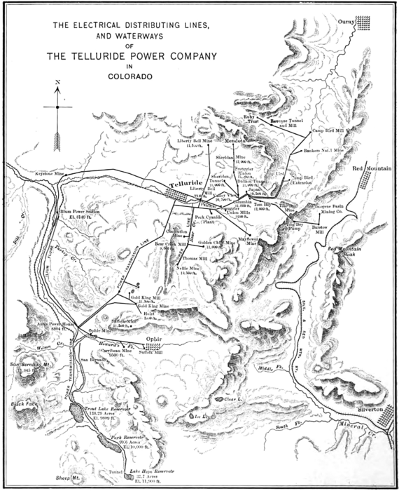
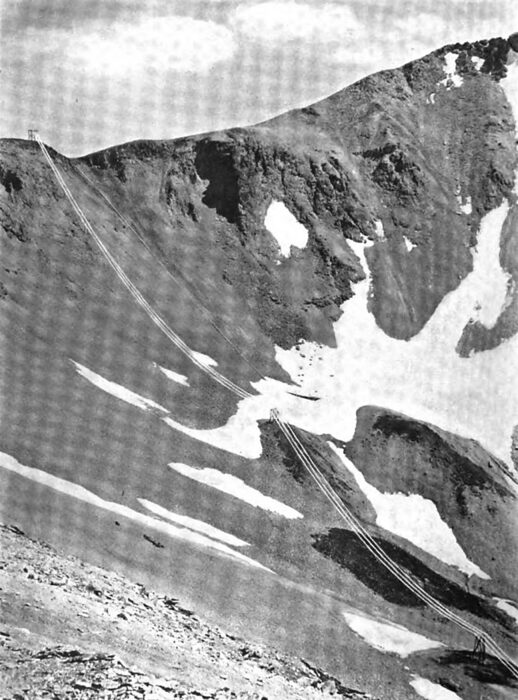
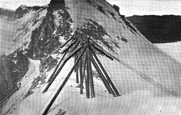
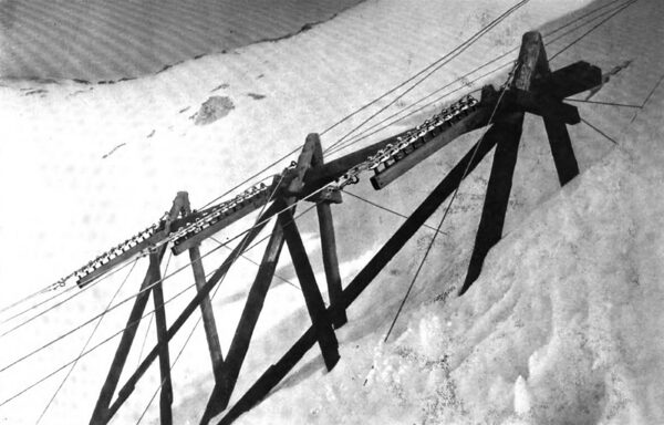
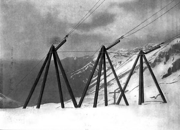
The long spans crossing canyons and "divides" surrounding Savage Basin may be worthy of note. These divides are bare ridges at an altitude of 13,000 feet. inaccessible in winter and swept by frequent snow-slides. Spans up to 1150 feet are used in order to reach safe points for supports. A number of these-supports, although simple and inexpensive, have stood for years without repair. The longest span is of No. 1, hard-drawn copper, supported by half-inch plough-steel cable, both being carried by the same insulators. The deflection is approximately 35 feet on a slope of 31 degrees. Another is of 3/8-inch soft iron cable, 1120 feet long, and has been in service five years. A third. 660 feet long, is of hard-drawn copper only, having 25 feet deflection. The strain insulators in all cases are a series of the usual line insulators and pins upon a longitudinal arm hinged to permit adjustment to span motion. They are simple, inexpensive, and entirely successful.
| |||
| One of the Motor Switch Boards of the Telluride Synchronous System |
A 10,000-volt underground transmission was put in operation at the Gold King mine in 1896. Power was carried through an unused tunnel, 1300 feet long, upon bare copper conductors 12 inches apart on standard line insulators, to a deep mining hoist equipped for electric power. The tunnel was always dripping with water, but no trouble was experienced during the several years of operation, although slight brush discharge or halo was at times observed.
An interesting installation to which power is furnished is that of the well-known Camp Bird, Limited, near Ouray. Nineteen motors and rotaries, in sizes up to 150 KW, drive crushers, Huntingtons, concentrators, compressors, pumps and hoists, aggregating in all about woo K W. Two underground transmissions, each a mile in extent, are in operation. Continuous current at 55o volts from two rotaries and a 65o ampere-hour storage battery operate three deep-mine hoists of 150 H. P., and an installation designed by Mr. C. S. Ruffner, now engineer of the Utah department, makes use of the alternating current transmitted at 10,000 volts through paper insulated, lead-covered cable, for the purpose of operating two 50 H. P. pumps.
 |
The success of the original plant prompted the manager of the company, Mr. L. L. Nunn, to institute a search for other water powers in the West, finding, as a result, that such powers were very remote from available markets, requiring much longer transmissions than theretofore used. Voltages higher than from 10,000 to 15,000 were not in commercial use, and were regarded as merely problematical; but two important water rights, already acquired in Utah and Montana, would have been worthless at such pressures. Mr. Nunn therefore determined in 1895 to undertake at Telluride an experimental transmission at higher voltages, to be installed and operated as a practical test for power purposes, and to determine, if possible, the problems peculiar to long distances and high pressures.
Two identical 75-KW, oil-insulated transformers were installed in the autumn of 1895, one at the Ames station and the other at the Gold King mill. They were designed for pressures varying from 15,000 to 60,000 volts by convenient steps. A separate pole line was equipped with three circuits of different characteristics upon three types of insulators.
Measurements with many special instruments were made, embracing the different voltages, styles of insulators, conductors and distances between them, and the conditions peculiar to the various phenomena met at every step. Observations upon a wide range of atmospheric conditions were made by means of United States Weather Bureau apparatus at either end of the line. The commercial feasibility of high pressures was demonstrated by the successful operation of the Gold King mill during a great part of the year at pressures from 30,000 to nearly 60,000 volts, as well as by continuous electrification for nearly a month during dry weather of a three-mile telephone circuit, upon telegraph insulators, at pressures rising from 10,000 to 40,000 volts.
| |||
| A Long Span at Red Mountain Divide |
| |||
| Another Long Span at Camp Bird Divide |
The change of the system from single to polyphase terminated actual transmission experiments. The reducing transformer was moved to the station, and another equipment, designed for polyphase tests, was ordered. The remaining time was devoted to open circuit losses, and to the verification of measurements previously made. This work continued until August, 1897, when construction was begun upon the Provo plant.
| |||
| An Open-Jir Switching Junction |
Much of the data obtained from these experiments was incomplete, requiring caution in its use, due largely to the time and study required in solving, step by step, the problems and difficulties met at every stage of the work. However, that much of value was obtained is shown by the subsequent successes at Provo. Sufficient had been learned to warrant the commercial adoption for the first time of 40,000 volts, nearly thrice the voltage of any previous plant; to lead to the manufacture of transformers which, after seven years' continuous operation, are still in daily service; to determine the design of the Provo-type insulator, the method of line construction, distance between wires, and the importance of wave form, and to make possible this great advance in long-distance, high-voltage transmission.
| |||
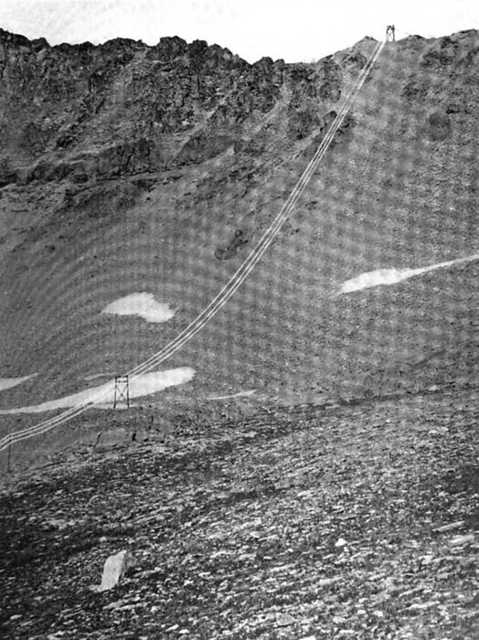
| A Tower on the Summit of Camp Bird Divide |
This experimental work, as clearly appears from the foregoing facts, was begun, carried on and finally utilised by the Telluride Company in the regular and necessary course of its growing business; yet it must be added that important services were rendered by Mr. V. G. Converse, under whose direction the transformers had been designed and constructed, and who participated throughout the greater part of the work during all the experiments with actual high-pressure transmission, and subsequently by Mr. Ralph D. Mershon in the elaborate instrumentation and laboratory practice, including a notably ingenious method of reading high-tension losses upon low-tension circuits, devised by him and used in substantiating the accuracy of the earlier measurements; also that different types of insulators were contributed by the General Electric and the Westinghouse Companies and by Mr. F. M. Locke on account of their friendly interest in the work.(1)
| |||
| A Side Hill Support in Edge of Snow Slide |
| |||
| Special Construction for Separation of Conductors |
The original plant at Provo contained two 750-KW, 60-cycle, 800-volt, three-phase General Electric generators, direct connected at 300 revolutions per minute to twin horizontal turbines under 125 feet head, a six-panel Wagner switchboard, two banks of oil transformers and two outgoing circuits. All contents, thus in duplicate, were assembled in two complete, independent units, designed for operation independently or paralleled at both high and low pressure. Prior to the power-factor indicator, a device which answered a somewhat similar purpose was installed, consisting of a wattmeter on the low-pressure paralleling bus with current coil in one bus and shunt across the other two. This indicated cross-current, and was used in the adjustment of field charges. Transformers were each 250 KW, 800 to 40,000 volts, star connected at both high and low pressure, with neutrals grounded.
(1) An interesting account of this work and some of the technical results may be found in Mr. Mershon's report quoted in Mr. Scott's paper before the A. I. E. E. at the Omaha meeting, in July [June], 1898.
Triple-pole air switches and four-foot fuses formerly connected each bank of transformers with its transmission line. One form of air switch, opening six feet, contained no metal except conductors, and was composed entirely of paraffined wood and rawhide, without porcelain, glass or other insulator. Others were sliding frames carrying line insulators.
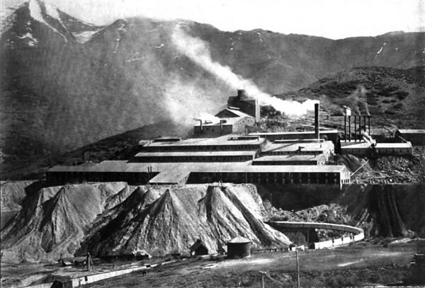
During the first year of operation the transmission comprised a single 32-mile line to one receiving point at Mercur, where the arrangement was similar to that at the power house, save that two reducing transformers were connected two-phase three-phase, grounded neutral, for 220-volt, two-phase induction motors. The Provo-Eureka line, 42 miles long, carries seven-strand aluminium cable equivalent to No. 4 copper. The Eureka-Mercur cross line, 28 miles long, equivalent to No. 5 copper, was added to complete the triangle thus formed and permit cutting out either of the three sides without interrupting service.
The Logan plant was completed in 1901, containing two 1000-KW, revolving-field alternators, direct connected at 400 revolutions to double discharge twin turbines under 212 feet head. This plant is connected with the Provo system by duplicate lines over 100 miles long, passing the cities of Ogden and Salt Lake. The Provo and Logan plants are thus operated in unison through nearly 200 miles of transmission. Distributing points at Mercur, Eureka, Bingham, Salt Lake and Provo are also junction points of the duplicate lines, equipped with switches in each incoming line, as well as in circuit with the transformers, so that in case of threatened trouble the patrolman can without delay have his section cut off for immediate repair without interrupting service.
| |||
| The Mercur Mill, Supplied With Power From the Provo, Utah, Station, Shown on Pages 192 and 193. the First Industry Operated by 40,000 - Volt Power |
The three conductors of each transmission form an equilateral triangle, 76 inches between wires, carried by a seven-foot cross-arm and the top of the pole. Extra long pins raise the insulators from 6 to 12 inches above the cross-arms, are of selected locust, kiln-dried and immersed from six to twelve hours in hard paraffine at 150° C. Cross arms are of Oregon fir, kiln-dried and soaked in boiling bitumen. Those upon the first line were attached in the usual manner with metal braces.
The burning of cross arms and poles on account of broken insulators, during prolonged wet weather, occurred most frequently at these braces. When the next lines were built, in 1899, treated wooden braces were substituted, with results so favourable that all metal braces were soon replaced. It was still observed, however, that even light leakage seemed to concentrate around the lag bolts, carbonising the wood and finally loosening the bolts.
For the Logan lines of 1900 and all later lines, therefore, the cross-arms were mortised through the poles and wedged and pinned with hard wood, thus discarding all metal except conductors. This construction was originated by Mr. A. L. Woodhouse, who, upon the close of the high pressure experimental work in Colorado, of which he had charge, became, and still is, superintendent of the Utah department. It has proved amply strong, not expensive, and during the four years' operation of the 400 miles thus constructed very few poles have been burned.
| |||
| The First 40,000-Volt Power Plant, Provo, Utah |
Provo type glass insulators, designed by Mr. V. G. Converse, have been used throughout. Many have broken, but these have usually shown the effects of gunshots or stones. In fact, there has not been a single breakage, except in one lot, improperly annealed, clearly due to either internal or dielectric stresses. It is difficult to see wherein any other insulators could have done better, unless bullet-proof. College laboratory tests to the contrary notwithstanding, leakage losses are inappreciable, except during severest storms, and then not serious where insulators are unbroken.
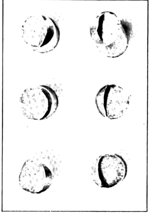
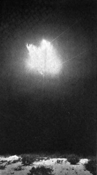
It is a mistake to suppose that Utah climate is favourable. During the rainy season it is as wet as any, and the alkali dust of the so-called salt storms is as trying as sea-coast spray. At times dense volumes of this impalpable dust from the Great Desert are accompanied by clouds or fog. In this damp, sticky state the dust completely covers to a considerable depth the under as well as the upper surfaces of insulators, as well as poles, cross-arms and pins. Over these surfaces streamers gradually creep until, meeting at the pole, they break into an arc, like that which was photo-graphed by Mr. C. E. Baker, the line patrolman at Mercur, and which has several times been published. A quick turn of the generator rheostat at the critical instant breaks the arc, without interrupting service of induction motors.
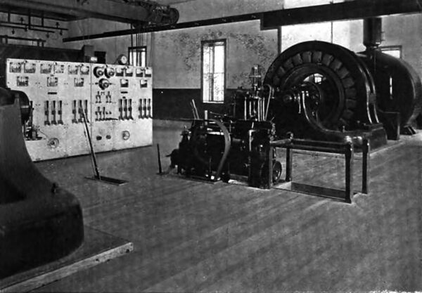
| |||
| The Interior of the Provo Power House |
The arrangement of power houses and transmissions already described is such that the opening of paralleling switches may resolve the system into a single transmission from too to nearly 400 miles in length with a generator at each end, yet side by side. If one generator be reversed, synchronised as a motor with the other and loaded by its waterwheel, any length of transmission may, by manipulation of a paralleling switch, be alternately cut in and out between them. Since switchboards and instruments are connected, measurements made are immediately comparable. In this manner losses and power factor may be measured, and the corrective effect of charging current observed.
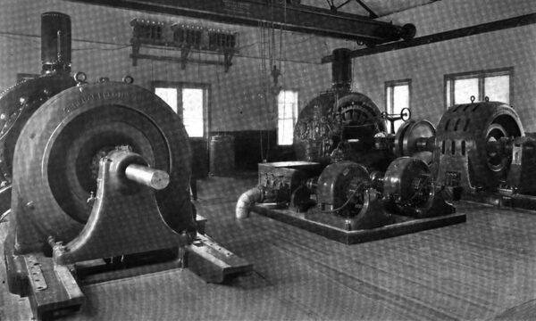
| |||
| The Interior of the Logan Power House |
Solid aluminium wire, first used in 1898, was slightly alloyed to increase strength, but proved worthless, breaking repeatedly with square, glass-like fractures. It was at once replaced with commercially pure, seven-strand cable, still in use. Similar cables have generally been employed for subsequent lines, while spans have been successfully increased to i8o and 200 feet, with less deflection than usual with copper.
The experience with oil transformers for 10,000 volts at Telluride, and the refusal of manufacturers to give any guarantees whatever for other transformers for higher pressures, led the Telluride Company, when undertaking this 40,000-volt transmission, to manufacture its own. The first equipment was made at the Wagner Company's works under designs and supervision of Mr. Converse. The later ones were made by the Converse Transformer Company.
| |||
| The Logan Power House |
 |
When erected, the oil in the tank and the transformer in an oven were slowly raised to, and then maintained during twenty-four hours at, a temperature of 125° C. The transformer was then immersed in the oil, and both continued at the same temperature for a further twenty-four hours.
As bearing upon the question of fire risk due to oil transformers, it may be of interest to note that of the large number of these high-pressure transformers used during the past seven years, chiefly in isolated sub-stations containing much wood and seldom visited, all but four are still in operation; that these four were destroyed by fire of doubtful origin, and that only one transformer has required repair other than change of oil.
 |
| Fracture of Alloyed Solid Aluminium Conductors |
The plant at Norris, Montana, designed and constructed in riot by Mr. 0. B. Suhr, Superintendent (now Resident Engineer of the Ontario Power Company), contains at present two low-speed, 1000-KW units.
| |||
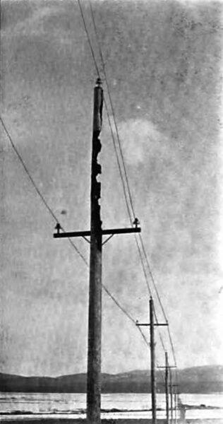
| Burnt Pole of Early Construction |
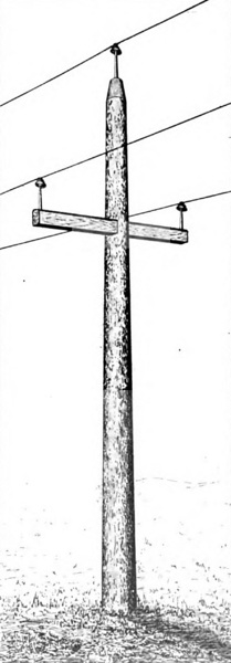 |
| Present All - Wood Pole Construction |
A duplicate transmission of 60 miles conveys power to the city of Butte. These lines, as well as both raising and reducing transformers, were designed for the use of 40,000, 60,000, or 80,000 volts. Longer pins are used than in Utah, and conductors form a triangle of 108 inches. While producing the present limited amount of power, and awaiting a suitable insulator, the lower voltage has been used.
| |||
| General View of Olmsted, Looking East, Showing New Provo Power House and Institute Buildings |
| |||
| A View of Olmsted Looking Toward Utah Lake |
In conclusion, it may be said that the Provo plant,the first transmission at more than 16,000 volts,while undertaken materially in advance of the art, and not exempt from its share of troubles, has, nevertheless, been fully successful as a financial venture, and not without value in the progress of the science. Long periods of perfect operation, monotonous in their uneventfulness, have proven beyond question the success of high pressures for long distances.
| |||
| Arc Caused by A Salt Storm |
The new and larger power house at Olmsted, at the mouth of Provo Canyon, completed this season, is modern in every detail. It contains three 3600-horse generators, operating under 340 feet head. Air switches and fuses are everywhere giving place to oil switches with time-limit automatics, and constant reconstruction to meet its increasing demands keeps the system, as a whole, abreast of present practice. Thus the Telluride Power Company, while again and again a pioneer in power transmission, must not be associated alone with the experimental methods of early days, but may in the future be found still engaged in progressive, practical, pioneer work.
