[Trade Journal]
Publication: Transactions of the American Institute Of Electrical Engineers
New York, NY, United States
vol. 26, p. 1273-1313, col. 1
A paper presented at the 24th Annual Convention
of the American Institute of Electrical
Engineers, Niagara falls, N. Y., June 26, 1907.
_____________________________________
Copyright 1907. By A. I. E. E.
THE TRANSMISSION PLANT OF THE NIAGARA,
LOCKPORT AND ONTARIO POWER COMPANY
BY RALPH D. MERSHON
On the seventh day of July, 1906, there was put into operation the first of the transmission lines of the Niagara, Lockport and Ontario Power Company. This event marks the inauguration of one of the first undertakings in the matter of distributing Niagara power over a large section of country, and the beginning of an enterprise which is one of the most important, and in some respects the most important, of its kind anywhere in the world.
| |||
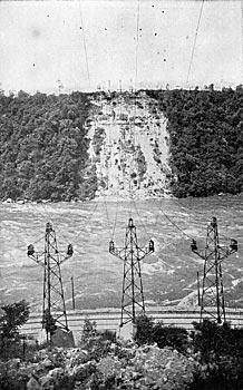
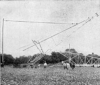
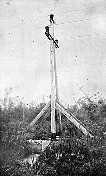
| Fig. 1 Niagara Crossing, General View |
The plans realized at present and contemplated for the immediate future, in the plant of the Niagara, Lockport and Ontario Power Company, involve a maximum transmission distance of 160 miles. This distance puts the plant amongst the longest transmissions of the world. As regards capacity, the plant of the Niagara, Lockport and Ontario Power Company is now one of the most important in existence, and, in the near future, its capacity will be far in excess of any other transmission system in the world. In addition to these points of importance, there are a number of engineering features somewhat out of the usual line of transmission practice which make the installation of interest from an engineering standpoint. Inasmuch as the description of such a plant is usually more satisfactorily accomplished through pictures than otherwise, they will be mainly resorted to herein, with the aid of only such brief text as may be necessary to cover points which cannot be well shown in illustrations.
| |||
| Fig. 2 Niagara Crossing, Water-Edge Towers, American Side |
The prospective system of the Niagara, Lockport and Ontario Power Company is a comprehensive one for the delivery of power in the United States within an economic transmission radius of Niagara Falls, and especially for its delivery in the northern and western portions of the state of New York. The company expects within the next two years to be transmitting 60,000 horse power, and its present right-of-way purchases are with reference to an ultimate transmission of 180,000 horse power. The plans of the company as at present laid out contemplate the transmission of this power by means of main lines and branch lines therefrom; the contracts for power being, wherever possible, made for delivery of the power at the main-line voltage of 60,000, less line drop. Where, however, the business of a given territory will justify it, the company will install step-down transformer stations for the delivery of power at a lower voltage. Each of the main transmission circuits will be capable of receiving and transmitting 30,000 horse power at 60,000 volts, and it is intended always to provide a sufficient number of spare main transmission lines to insure continuity of service on the main line. Spare lines will be provided in the case of branch lines only when the latter are of considerable importance.
| |||
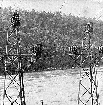
| Fig. 3 Niagara Crossing Top of Water Edge Towers |
The Niagara, Lockport and Ontario Power Company is only a transmission company; that is, it buys the power to be transmitted and has, therefore, no generating plant of its own. The power for the transmission is generated in the hydraulic power station of the Ontario Power Company, situated on the Canadian side of Niagara Falls. The water for this station is taken from the Niagara River, some distance above the falls, whence it is brought to a point at the top of the cliff, a short distance below the falls, through underground steel conduits, and from this point delivered through underground penstocks to the power station located at the bottom of the cliff, near the foot of the falls.
The power house contains the generating units with their exciters and switchboard apparatus. The generators have a capacity of 7,500 kw. each, and deliver three-phase 25-cycle current at 12,000 volts. From the power station the current is taken at 12,000 volts to the transforming and switching station of the Ontario Power Company located on the bluff above the falls. It is stepped up from 12,000 volts to 62,500 volts, and at this latter voltage delivered to the transmission lines. The transmission lines of the Ontario Power Company extend from its transforming station to a point some six miles farther down the Niagara River, at which point the lines connect to circuits spanning the Niagara River. The Niagara, Lockport and Ontario Power Company takes delivery of the electric power at the international boundary line in the middle of the Niagara River.
| |||
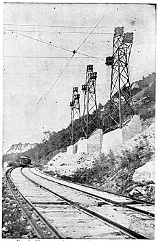
| Fig. 4 Niagara Crossing, Cantilevers, American Side |
At the present time, the Niagara, Lockport and Ontario Power Company has in its possession a private right-of-way 300 feet wide from the Niagara River to the town of Lockport, about 16 miles east; from Lockport east to Mortimer (six miles south of Rochester) a private right-of-way 200 feet wide, a distance of about 57 miles, from Mortimer to Fairport a 100-foot private right of-way a distance of 10 miles; and from Fairport to Syracuse a private right-of-way 75 feet wide, a distance of 71 miles. From Lockport south in the direction of Buffalo, the company has a private right-of-way 100 feet wide. In addition to this, the company has the right to install transmission lines on the right-of-way of the West Shore Railroad and has acquired the necessary private right-of-way to get from its main private right-of-way to that of the railroad company.
| |||
| Fig. 5 Pipe Towers |

The installation which the company has now in operation is for receiving 30,000 horse power and delivering this amount, less the line loss. The main transmission consists of two lines in duplicate. From the Niagara River to Lockport, a distance of 16 miles, there are two lines on the company's private right-of-way, each capable of transmitting 30,000 horse power. From Lockport to Mortimer, a distance of 57 miles, there is a line on the company's private right-of-way having a capacity of 20,000 horse power. From Mortimer east to Syracuse, a distance of 81 miles, there is a line on the company's right-of-way having a capacity of 10,000 horse power. From Lockport to a point about 11 miles east, thence south on the company's private right-of-way to the West Shore Railroad, and thence on the West Shore Railroad to Pittsford is a line having a capacity of 20,000 horse-power. From Pittsford on the West Shore Railroad right-of-way east to Syracuse is a line having a capacity of 10,000 horse power. From Lockport south to a point south of Buffalo, there are two transmission lines on the private right-of-way of the company, each having a capacity of 30,000 horse power. These two lines south are tapped into the two lines coming from the Niagara River to Lockport, and constitute, therefore, at present, a branch line, but they will be eventually extended clear through to the Niagara River, and it is in anticipation of this extension that they are constructed with the full capacity of 30,000 horse power. As will be seen from the above, the distance from the Niagara River to Syracuse is 154 miles. In addition to this, the transmission from the transforming station of the Ontario Power Company to the Niagara River has a length of about 6 miles, making, as previously mentioned, a maximum transmission of 160 miles.
| |||
| Fig. 6 Transmission Lines From Lockport to Buffalo |

| |||
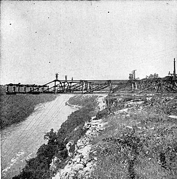
| Fig. 7 7-950 - Foot Span Over Buffalo Creek |

It will be seen, therefore, that in delivering power in Lockport, and in the neighborhood of Buffalo, Rochester, Syracuse, and at intermediate points, the company will have transmission circuits in duplicate, each capable of transmitting the full amount of power to be delivered at the several points.
| |||
| Fig. 8 1253-Foot Span Over Swamp |

| |||
| Fig. 9 Cross-Connecting and Disconnecting Switches and Open-Air Fuses at Point of Junction of Auburn Branch Line and the Main Line |

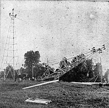
As previously stated, the power is brought across the Niagara River by means of aerial cables spanning the river, and delivery of the power is taken by the transmission company at the international boundary line. The cables are brought across the river in three spans; one span from steel cantilevers at the top of the cliff on the Canadian side to steel towers at the water's edge on the Canadian side; another span from the water-edge towers on the Canadian side to the corresponding towers on the American side; and a third span from the steel water-edge towers on the American side to the steel cantilevers at the top of the cliff on the American side. The use of cantilevers is necessitated mainly by reason of the steep angle at which the cable descends from the top of the cliff. Their use also makes possible the required clearance between the cable and the slope of the gorge, a point of special importance on the American side in view of the fact that one of the branch lines of the New York Central Railroad is on the American slope of the gorge. The steep slope of the cable at the cantilevers would make it bear upon the upper petticoat of the insulator supporting it, if the cable were attached to the top of the insulator in the usual way. As will be seen by the photographs of the cantilevers, this difficulty is obviated by attaching the cable to a steel cross-bar supported at each end by an insulator.
| |||
| Fig. 10 Top of Double-Guyed Steel Tower |

| |||
| Fig. 11 Tower in Montezuma Swamp |

The steel cantilevers and the river-edge towers are all designed to withstand the most extreme conditions of sleet and wind that will probably ever exist. The requisite mechanical strength of the insulation at the points where the cables are attached to the steel structures is obtained by using a sufficient number of line insulators, and the proper distribution amongst these insulators of the forces which will come upon them is effected by means of malleable cast-iron caps cemented to the tops of the insulators and to which the cables are fastened.
| |||
| Fig. 12 Line Structure Lightning - Arrester on Steel Tower |

It was originally intended, and provided for in the contract with the Ontario Power Company, that just after crossing the river the 60,000-volt lines should be led into a switching station in which, by means of 60,000-volt electrically operated oil-switches, it would be possible to interchange the circuits coming into and going out of this station. The building itself for this switching station has been completed, but, before the equipment of the station had been installed, arrangements were made with the Ontario Power Company to defer the outlay for such equipment until the use of it should be more necessary than at the present time, when only two lines are in operation.
| |||
| Fig. 13 Stringing Line Cable |

The main-line construction of the Niagara, Lockport and Ontario Power Company is most substantial. With the exception of that portion of the main line on the West Shore Railroad between Churchville and Syracuse, the main-line structures are all steel towers, and the standard line-span is 550 feet. On some portions of the transmission line, however, much longer spans are used, the longest at present installed being 1,253 feet. In some cases these long spans had to be provided with towers heavier than the standard; in other cases it was possible to put them up with little, if any, modification of the standard tower construction. For a number of reasons, the principal one being lack of the requisite space, it was necessary to use on the West Shore right-of-way between Churchville Syracuse wooden construction of special design which will be described later on, the standard span being 220 feet. In every case on the 60,000-volt lines, each line of towers or wooden structures carries only one three-phase circuit. The main line conductors installed so far are all of them of aluminum cable, except on a portion of the line between Mortimer and Syracuse where, because of the long spans employed, it is preferable to use copper.
| |||
| Fig. 14 Tower Delivered Ready for Assembling |

| |||
| Fig. 15 Assembling Tower (1) |

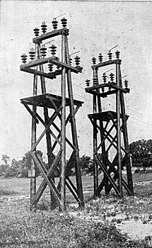
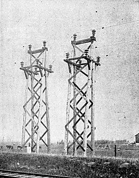
The first of the steel towers installed were of the tripod type, made of lap-welded pipe; but the later towers, and those which in the near future will be installed, are of structural shapes and galvanized. The design of these two types of towers is shown in the accompanying illustrations. Two types of the structural tower are shown. The earlier ones were non-interchangeable; that is, the guyed towers differed in construction from the unguyed towers. The later towers are interchangeable; that is, the guyed and unguyed towers are exactly similar except for the guys and double insulators of the former. Contrary to the practice which has heretofore been followed in the matter of steel line towers, the towers of this transmission line are mounted on foundations of reinforced concrete. These foundations are designed to utilize the weight of the earth around them in resisting uplift. The towers and their foundations are capable of withstanding transverse forces which will be brought upon them when the line cables are covered with 0.5 in. of ice all around them and the wind blowing transverse to the line at a velocity of 75 miles an hour. The towers have the same strength in all directions; that is, they are capable of withstanding the same forces in the direction of the line that they are capable of withstanding transverse to the line. To meet the contingency, not likely to occur, of all three cables breaking at once, in which case the full tension of all the cables might be brought upon the towers, there are at intervals along the line certain towers guyed both ways in the direction of the transmission line, and having double fixtures. The strength of these guyed towers is such as would enable them to withstand the forces that would obtain under the extreme conditions outlined above, if all the line cables should break. The guyed towers will, there-fore, terminate any progressive failure of the line which might under extreme conditions be instituted by the breaking of cables.
| |||
| Fig. 16 Assembling Tower (2) |

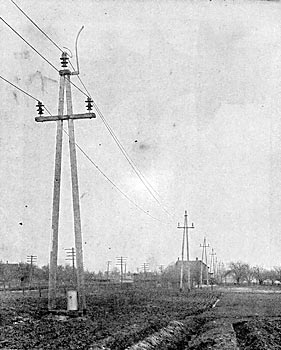
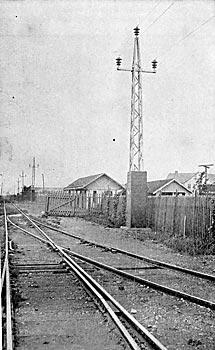
As stated above, on the West Shore right-of-way it was necessary to use wooden line structures. The type of construction employed is that which has been designated by the company as "A-frame construction." It is clearly shown in one of the accompanying cuts. By adopting this type of construction, in which each structure consists of two poles instead of one, it is possible to use twice the length of span that would be used in ordinary wooden pole construction and employ, therefore, one-half the number of insulators. As stated above, the standard length of span of this type of construction is 220 feet. On some portions of the West Shore right-of-way it was necessary to use steel construction, and in such places there were installed galvanized lattice steel poles, such as are shown in one of the illustrations. The span on these poles is the same as that on the A-frame construction.
| |||
| Fig. 17 Foot of Tower, Showing Method of Fastening Tower to Foundation |

In a number of places on the main line, both on the West Shore and on the private right-of-way, it is necessary to cross the Montezuma marsh. Where this marsh was crossed with steel tower construction, the concrete foundations for the steel towers were built by first excavating the swamp through the soft mud until the soft marl, forming the sub-stratum of the swamp, was reached. On the marl was laid a platform of two layers of corduroy, and on this platform was built the concrete foundations, the weight of which was made sufficient to take care of any uplift which will come upon the towers. These foundations were installed, some of them, in cold weather and, so far, they have shown no settlement. Where this marsh was crossed with A-frame construction, it was found in places much too expensive to excavate for the proper foundation for the A-frames. The A-frames were, therefore, installed by laying on top of the ground four line poles in two pairs, the poles of one pair being parallel to the line, and the poles of the other pair being at right angles to the line. These poles were spiked together at the point where they cross, and at the point of crossing the A-frame was spiked to them, the A-frame being further secured to the poles by braces. On each end of each pair of poles was spiked a box, built up of planking and filled with stone, in order to give sufficient weight to take the uplift due to any pull at the top of the tower. This structure, while far from beautiful, has, so far, proved very satisfactory. The tower construction and the A-frame construction in swamps are shown in the illustrations.
| |||
| Fig. 18 Tower Foundation Dug Up for Purpose of Relocation |

It will be noted that, in some of the illustrations of the towers and A-frames, there is shown a horn attached to a cap on the top of the insulator and another horn alongside of it fastened to the structure and extending some distance above the insulator. This comprises a combined line-structure lightning-arrester, or spark-gap, and lightning-rod. It has been decided to make a careful trial of this method of protection of the line before resorting to a grounded cable; partly because of the great expense of the grounded cable, and partly because there is no reason to think, so far, that it will necessarily afford complete protection in every case. For the present, these line- structure lightning-arresters will be installed only on the top cable, in view of the fact that during the last lightning season, in the course of which a number of insulators were broken by lightning, more than three-fourths of the insulators so broken were top insulators.
| |||
| Fig. 19 Erecting 75-Foot Tower (1) |
| |||
| Fig. 20 Erecting 75-Foot Tower (2) |
| |||
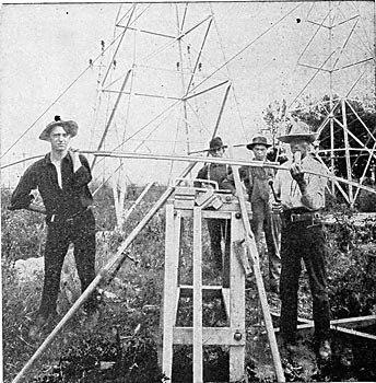
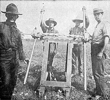
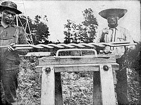
| Fig. 21 the Making of A Joint (1) |
| |||
| Fig. 22 the Making of A Joint (2) |
| |||
| Fig. 23 the Making of A Joint (3), Joint Complete |
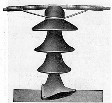
The insulator used on all the main-line construction is one especially designed for this plant by the writer. It has probably the greatest factor of safety as regards flashing, etc., of any insulator in practical use to-day, and is considerably larger and heavier than any insulator of which corresponding use has heretofore been made. It consists of three shells nesting in one another and cemented together by means of neat Portland cement, the whole insulator being cemented in a similar manner to a steel pin before attachment to the tower. The insulator is clearly shown in one of the illustrations. The total height of it from the edge of the lower petticoat to the top of the head is 19 inches. The diameter of the upper petticoat is 14.5 inches. The insulator used on some of the branch lines is smaller and less expensive than that for the main line, partly because the branch lines receive in general a somewhat lower voltage than the main line and partly because the lines, carrying the small amounts of power they do, are not considered to be entitled to the same insurance as the main line. Each branch line has in series with it, at the point where it is tapped off the main line, 60,000-volt outdoor fuses to cut out the line in case of trouble on it. The fuses consist of lengths of thin copper wire 16 feet long, run through an ordinary small rubber bathroom hose and laid in clips on top of a wooden bar supported at each end and at the center by line insulators mounted on poles.
| |||
| Fig. 24 60,000-Volt Main-Line Insulator With Tie and Cable Protection |
The fuses are parallel to each other in the same horizontal plane, and the distance from center to center is about 25 feet. These fuses have so far proved very satisfactory but will probably in time be replaced with fuses of the explosion type. The outdoor 60,000-volt fuses are shown in one of the illustrations.
There are only three sizes of cables used on the main transmission line, designated by the company as 3/3, 2/3, and 1/3 respectively. The 3/3 cable is aluminum cable, consisting of 19 strands, and having a total area of 642,800 cir. mils, being equivalent to 400,000 cir. mils copper. The areas of cross-section of the other cables are respectively two-thirds and one-third that of the large one.
| |||
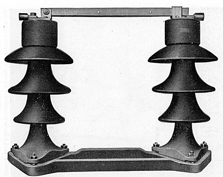
| Fig. 25 60,000-Volt Outdoor Line Disconnecting Switch |
In ordinary straight-away work, the cable lies in the top groove of the insulator, and the pull of the cable is taken care of by means of two aluminum wire ties around the neck of the insulator. One of these ties extends each way along the cable. The tie itself consists of a single loop around the neck of the insulator, the two ends of the loop being twisted around the line cable. The result is that the cable is not really fastened to the insulator at all, but simply lies in the top groove. The ties do not, therefore, perform any function, except when there is a pull on the cable tending to slide it in the direction of its length. The advantages of such a tie are twofold. first, the full strength of the tie wire is developed. which is not the case if a tie is twisted or "pig-tailed," since in such case the tendency is for the tie to cut itself in two at the twist; secondly, the tie does not damage the soft aluminum cable, as would be the case with most of the other ties usually employed.
| |||
| Fig. 26 Standard A-Frame Construction Showing Line Structure Lightning Arrester |
| |||
| Fig. 27 A-Frame Construction, Montezuma Swamp |
In other than straight-away work, and where it is desirable that the method of fastening to the insulator shall be such as will withstand a pull equal to the full strength of the cable, in case the cable should break, the tie mentioned above is not used, but instead there is employed a cable-clamp and a yoke extending each way on the cable.
| |||
| Fig. 28 A-Frame Disconnecting Switches |
| |||
| Fig. 29 A-Frame Transposition |
In every case the cable near the insulator is protected from possible arcs, so that in the event of an arc there will be a chance for the circuit-breaker at the generating station to open before the cable shall have been burned off. This protection is accomplished in the top groove of the insulator by means of sheet aluminum wrapped around the cable at this point to a thickness of inch, and is accomplished on each side of the head of the insulator to a distance of 12 inches from the head partly by the turns of the tie-wire mentioned above, and partly by an additional serving of tie-wire. Where, in the case of the use of cable-clamps, no tie-wire is used, its absence is made up for by additional serving. The photographs show very clearly the methods of attaching the cables to the insulators and the methods of protecting the cables from arcs.
The ends of the line cables are connected by means of twisted-sleeve joints. The method of making these joints is shown in the illustrations.
At intervals along the line there are provided disconnecting switches for sectioning the line to facilitate testing out in case of trouble, or cutting out any portion of the line which is damaged. There are also provided at certain points, in connection with these disconnecting switches, cross-connecting switches, enabling the interconnection of different portions of the two lines.
| |||
| Fig. 30 Galvanized Steel Poles on Railway |
On a considerable portion of the company's right-of-way is a wagon road, for use in patrolling the line and delivering material for construction or repair. At certain points along the line there are patrol houses for the storage of material, for taking care of teams, and for the comfortable housing of the patrolmen. Each house has in it a sleeping room, kitchen, and sitting room. On all of the transmission lines, also, the company has a private telephone line on a separate set of wooden poles. Taps from this line are brought into each of the transmission houses, and in addition to this the line patrolmen have portable telephones which can be connected to the telephone line at any point.
Most of the contracts which the company has for the supply of power cover the delivery of the power at the main-line voltage.
[not finished]