[Trade Journal]
Publication: American Institute Of Electrical Engineers
New York, NY, United States
p. 573-598
A PRACTICAL METHOD OF PROTECTING INSULATORS
FROM LIGHTNING AND POWER ARC EFFECTS
BY L. C. NICHOLSON
The problem of adequately protecting a high-tension transmission line against injury by lightning is an important one. Various solutions have been proposed, but it is generally conceded that complete protection of high-tension porcelain insulators from destruction by lightning effects has not been attained. Grounded overhead conductors, relief gaps on insulators, lightning rods supported on the transmission line structures or on separate structures alongside, and station-type lightning arresters at points particularly exposed, are some of the principal preventive devices employed, any of which serves to ameliorate conditions, but none of which affords ideal protection to the line.
| |||
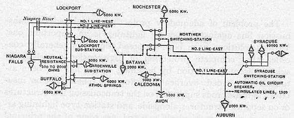
| Fig. 1. - Diagram of Transmission Lines and Stations 1909 |
| |||
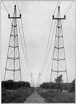
| Fig. 2. - 55-Ft. Tripod Pipe Tower |
| |||
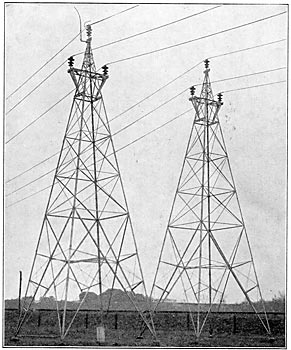
| Fig. 3. - 55-Ft. Structural Steel Towers, Showing A Relief Gap, As Used in 1907 |
The 60,000-volt transmission lines of the Niagara, Lockport and Ontario Power Company from Niagara Falls to Syracuse and other cities in western New York, were placed in operation in July, 1906, just in the midst of the lightning season, and without any of the usual methods of line lightning protection. Troubles developed which, though not unexpected, proved of serious consequence to the successful transmission of power during lightning storms. There was little opportunity in that season to adopt any corrective measures, either experimentally or otherwise, but in the following years the company has exerted every effort to ameliorate these troubles.
| |||
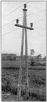
| Fig. 4. - 35-Ft. Wooden A-Frame Structure |
The experience of four years has served to indicate something of the real nature of lightning effects which result in insulator failures, and has led to the development of an inexpensive and efficient means of protection. The object of this paper is to relate the experiences and experiments leading to the protective measures finally adopted, which from one summer's trial appear to be sufficient.
This plant was thoroughly described by Mr. Ralph D. Mershon in a paper presented at the Niagara Falls Convention June, 1907 [Transaction AIEE, Vol. 26, part 2, p. 1273]. For purposes of reference, Fig. 1 shows the extent and description of lines, the connection and approximate capacity of the stations.
| |||
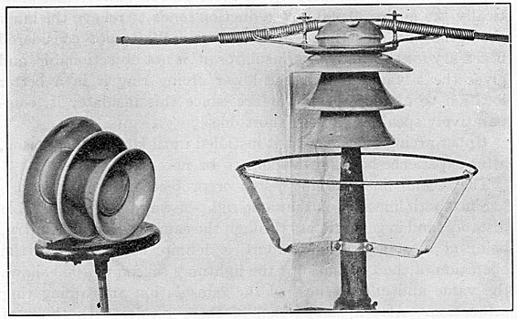
| Fig. 5. - 3-Part Main Line Insulator |
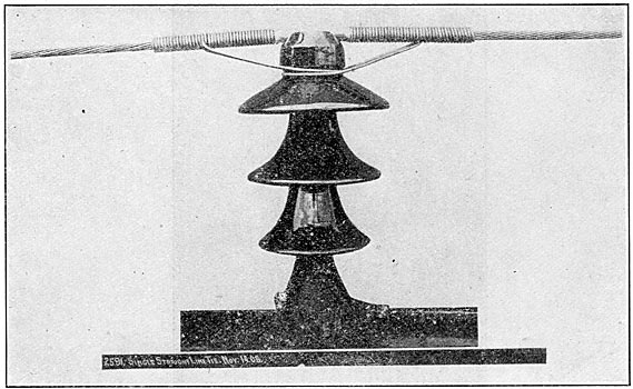
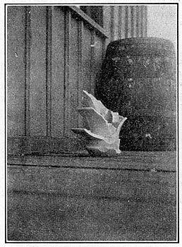
Figs. 2, 3, and 4 show types of line structures employed. In all cases insulator pins are of steel and are grounded. Fig. 5 shows the principal insulator used, and, with the exception of a few smaller ones of the same general design, the only type of insulator employed until 1909. This is known as the " 3-part main line " insulator. Its principal dimensions are:
Diameter of headpiece, 14 1/2 in.; diameter of intermediate shell, 13 in.; diameter of center shell, 11 in.; length of intermediate shell, 12 in.; length of center shell, 17 in.; height over all, 19 1/2 in. The dry flash-over voltage, that is, the voltage which will cause a flash-over when the surface is dry and clean, is 195,000. The wet flash-over voltage at 1/5 in. per minute precipitation at 45 degrees is 120,000.
Electrical tests on these insulators before their erection on the line consisted of 75,000 volts, three minutes on each part before assembling. The complete insulator was not tested after assembling.
During 1906 only one line was in service to various points. By the beginning of the lightning season of 1907 the second (duplicate) line was placed in service, making a total mileage of 400, containing 7000 structures and 23,000 insulators. Except for the addition of a few single branch lines from time to time, the lines have been virtually the same for three years. Switching facilities and general operating conditions, however, have been constantly improved. Since early in 1908 automatic oil circuit-breakers have been used in the duplicate lines at all important stations and paralleling points, making possible automatic sectionalizing of lines and a quick restoration of power in case of an interruption.
Lightning troubles have been entirely confined to the line. No station troubles, chargeable to lightning, have developed.
Experiences clearly shows that lightning in the vicinity of the line induces high potentials between the line conductors and earth. This potential causes one or more insulators in that immediate vicinity to flash over or puncture, or to be shattered in some part or parts, even though no flash-over or puncture occurs, or to be shattered by the power arc following the initial flash-over or puncture. These various causes intermingle their effects so as to obscure the first cause. Thus it has been found that insulators may be shattered completely either by pure lightning stresses, or by the heat of a power arc which follows the initial discharge from conductor to pin over the outside surface. Moreover, an insulator may puncture by lightning, and subsequently be shattered by the heat of the power current passing through the puncture, in which case it is impossible to say whether the puncture preceded the shattering or vice versa. A fairly concise idea of the nature and magnitude of the destructive forces may be gained by a study of the broken insulators in place.
| |||
| Fig. 6. - Insulators Removed From the Line After Damage by Lightning and Power Effects. |
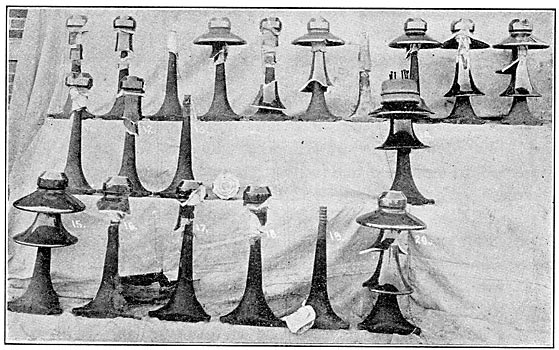
Fig. 6 shows a collection of twenty derelicts, resulting from a single severe storm, and gives a fair representation of how insulators are destroyed by lightning in combination with high-power effects.
The usual cases of line disablement involves a single insulator, which is either punctured from the cable or tie-wire to the top of the pin, or, being sufficiently strong to resist puncture, is broken by the flashover arc. Frequently several neighboring insulators are more or less damaged by what appears to be the effect of sudden mechanical forces which shatter or break the shells very much as a hammer blow would destroy them.
Extreme cases infrequently occur when many insulators in a restricted locality are entirely destroyed. Such disturbances usually center at a particular line structure on which all the insulators may be entirely destroyed, and one or more insulators on several adjacent structures in each direction destroyed or injured, the injury decreasing in severity away from the focus. Even in the most severe cases, however, the entire effect is confined to within 2,000 feet of the line. Such accidents are attributed to direct strokes on or very near the line. The mechanical forces exerted on insulator parts in such cases appear to be enormous, breaking the porcelain into small bits of irregular and curious shapes, and distributing them over the right-of-way for several hundred feet. Fortunately these extreme cases are of rare occurrence and do not enter largely into the lightning protection problem.
Just where direct stroke effects leave off, and just where induced potential effects begin and end, is, of course, indefinite. It is definitely known that a stroke 500 feet distant may cause a flash-over or puncture. It is thought that disturbances may be felt from bolts 2,000 or 3,000 feet away, this being also determined by the size of the discharge, and perhaps by electrostatic conditions in general.
The insulator problem as outlined above presented itself by the end of the lightning season of 1906, although 'at that time its nature was not appreciated as fully as it became later in the light of the subsequent experience. Thirty-five insulators were disabled by puncturing or shattering, out of a total of 12,000 installed. These breakages occurred on eight different occasions and consequently caused as many extended interruptions to parts of the service. In addition, there were ten momentary interruptions caused by short-circuits or grounds which tripped the controlling circuit-breaker, but did not disable the line.
Analysis of the insulator failures with respect to their location showed a very remarkable result. The number of insulators disabled on the top wire was four times the number disabled on a single side wire, or twice the number disabled on both side wires.
This result formed a basis for corrective measures which were taken previous to the lightning season of 1907. These devices consisted of relief gaps installed on insulators at regular intervals on the top wire of both duplicate lines, and the installation of high resistances in the neutral earth connections of star-connected transformers. Fig. 3 shows the type and construction of the relief gap which was employed.
These gaps were spaced 2200 feet on approximately 240 miles of line and 4400 feet on 100 miles, while on 60 miles no gaps were installed. At the time of selecting these spacings there was very little data for guidance. The only definite information available was that during 1906, before the lines were used, insulators were destroyed within a mile of a point where all three conductors were short-circuited and thoroughly grounded. The 2200-and 4400-foot spacing of the relief gaps on the top wire was adopted in an experimental attitude, the intention being to increase or decrease these distances as future experience dictated. The width of gap first adopted was six inches, corresponding to a discharge voltage of 70,000 volts, depending more or less upon weather conditions. This was also a subject of experiment.
It was intended by proper spacing and setting of the relief gaps, to limit the maximum possible voltage between top conductor and earth to less than the puncture or flash-over value of the insulators, and thus prevent the failure of insulators on the top wire due to the usual lightning effects. It was also expected that when discharging through the relief gaps, the top conductor would act to some extent as an overhead grounded conductor, and in this way afford some protection to the two side wires. An adjustable concrete resistance of 500 to 2000 ohms was connected in the neutral earth connection of the sending transformers, and 5000- to 10,000-ohm resistances at five different sub-stations in the neutral earth connection of star-delta connected receiving transformers. The purpose of installing these resistances was primarily to limit the discharge current to earth from the top wire through the relief gaps to a value which would not disturb operation, and the arc of which would quickly follow up the horns of the gap and discontinue. In the same way it was thought that these resistances would limit the power-current over an insulator containing no gap, in the event of a flash-over, to a value which would not work such havoc to the insulators as had formerly occurred when operating the system with thoroughly grounded neutrals. The 5000- to 10,000-ohm sub-station resistances were, of course, not necessary to attain the end sought. They were installed as a precautionary measure against abnormal potentials which might accompany grounds on the system. Their use was later discontinued, all neutrals except that at the generating station being insulated.
The operating results of the lightning season of 1907 did not fully justify the use of the relief gaps from a theoretical standpoint, and showed them to be rather an objection than an advantage from a practical operating standpoint.
It was early apparent that the gaps perfectly protected the insulators containing them, but that their protective influence was felt very slightly a short distance away on the same conductor, and was not felt at all on the two lower conductors This was true with gaps set as low as 41 in.
The following tabulation shows the season's results:
|
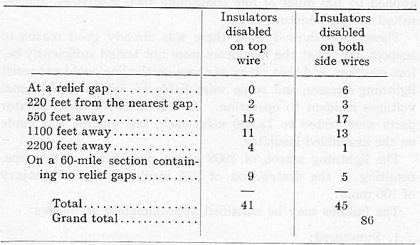
Insulators on line - 23,000.
Relief gaps on line - 750, approximately 25 per cent of which discharged one or more times.
These results demonstrate the extreme localization of lightning effects and the difficulty with which the charges travel along a conductor.
It appears from this table that the net effect of the use of the gaps was to save some insulators on the top wire. The number of line breakdowns was not reduced, while voltage disturbances and momentary interruptions were numerous. For this reason the relief gaps were removed before the lightning season of 1908. The grounded horn was left in place to act as a lightning rod. The concrete neutral resistance at the generating station was retained to prevent short-circuits between any one phase and ground.
A study of the insulator failures of 1907 showed that the majority of them were due to puncture, usually from the tie-wire in the neck to the top of the pin. A few punctured vertically from the cable to the pin. Approximately 25 per cent, and perhaps more, were shattered by power arc following a complete or partial flash-over. Comparatively few, it is believed, were shattered by direct stroke, although about 40 were injured by lightning stresses, but were not incapacitated thereby.
In view of the large proportion of punctures, it was decided to apply high potential to the lines and to weed out the weak insulators. This proved to be a slow and expensive process, so that very little was accomplished before the advent of lightning in 1908. A three-minute test of 100,000 volts to ground was applied to 109 miles of line containing 4000 insulators, and resulted in the puncture of 80.
These tests showed what there was already good reason to suspect, viz.: that the insulators were not tested sufficiently before erection, and that many of those on the line could not resist lightning stresses, and some were liable to fail from abnormal voltages incident to operation. As stated above, the insulator parts were tested to 75,000 volts each, but no test was made on the assembled insulator.
The lightning season of 1908 was a particularly severe one, resulting in the destruction of 226 insulators and the injury of 100 more.
The failures may be classified approximately as follows:
1. Punctured:
Top wire ........ 75
Side wires ...... 39
Total ........ 114
2. Shattered by direct stroke:
Top wire ...... 22
Side wires ...... 9
Total ......... 31
The 100 insulators which were injured were damaged by lightning stresses, or by power arc effects. They were still operative, however, and were replaced at convenience.
The lesson of the year was not new, but it showed more forcefully than had been realized before, that even if all insulators were capable of resisting puncture, they would continue to be shattered by a power arc following a flash-over. It was argued that by the proper testing of all insulators puncture could probably be prevented, but the fact that such a large number had been already destroyed by flash-over gave little reason to suppose that insulator losses and line interruptions could be materially reduced by providing puncture-proof insulators. They must be also fire-proof.
The only practical way of making the insulators puncture-proof was to remove them from the line, test each one to its dry flash-over voltage and return the perfect ones to the line. There was some question as to whether or not such a test would be effective, since an insulator which would flash over under 25-cycle voltage from a testing transformer, might puncture under the sudden attack of a lightning shock. However, the fact remained that insulators, presumably sound and dry, had flashed over in service because of lightning, rather than puncture, and this justified the belief that a 25-cycle dry flash-over test was sufficient. Subsequent experience has verified this conclusion.
| |||
| Fig. 7. - Arcing Rings, to Prevent Injury to Insulators by Power Effects. |
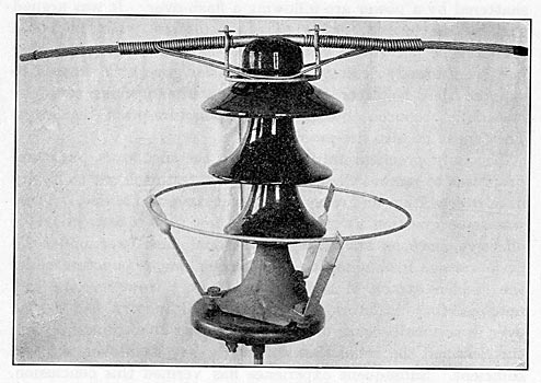
A device for rendering insulators fire-proof, or rather proof against injury by power arc in the event of a flash-over, was developed to meet an obvious need. As shown by Fig. 7, this device consists of two metal rings concentric with the insulator, a lower one which is situated near the base being considerably larger in diameter than the insulator parts, and supported by grounded metal risers attached to the pin; and an upper one somewhat larger than the neck of the insulator, just opposite the tie-wire, suspended from the transmission cable, and electrically connected to it. Details of construction are evident from the figures.
These rings serve as electrodes, to which the power arc automatically transfers immediately after its formation between the tie-wire and pin, over the surface of the insulator. When holding between these rings, the arc is removed sufficiently from the insulator to prevent injury to the porcelain by heat.
It was determined experimentally that the intense and concentrated heat at and near the ends of a large power arc is largely responsible for the damage wrought. This is particularly true of the lower terminal which passes up the pin to the heart of the insulator and shatters it. In other words, the insulator is broken from the bottom upward, by the lower end of the arc. The upper terminal, located on the tie-wire, is not so destructive, on account of the tendency of the arc to flare upward and away from the porcelain. If, however, the very crater of the arc comes into actual contact with the porcelain, by reason of being located on the nether side of the tie-wire, or by reason of burning the tie-wire in two, which it may do if it remains at a single point, the headpiece of the insulator will be broken.
Considerable experimenting with high power arcs showed that the lower portion of the arc was averse to assuming anything like a horizontal position. It very much preferred not to make the bend about the base of the insulator to reach the pin. Thus, it was found that the lower arcing ring would take the arc immediately after its formation to the pin, (which was accomplished by means of a fuse from tie-wire to pin, placed well up under the insulator parts) almost irrespective of the location of the ring with reference to the base of the insulator. On a quiet summer day, with practically no air movement to drive the arc away from the insulator, and naturally cause it to attack the ring, it was found that the arc instantaneously transferred from the pin to the lower ring, even though the ring was 20 in. larger in diameter than the base of the insulator, and as much as 4 in. below the base. The flaring nature and large size of these arcs, together with their tendency to assume an upright position afford the explanation of these results.
In the absence of wind it was apparent that the arc traveled rapidly from place to place around the insulator, and did not remain in any one place long enough to burn the tie-wire seriously. For this reason the headpiece of the insulator did not suffer, except perhaps to lose a little glaze. Under wind conditions, however, the arc hides behind the insulator on the leeward side and remains at or near one place on the tie-wire, sometimes burning it in two, and by coming into actual contact with the porcelain causes a breakage of the headpiece, but only the headpiece. The cure for this condition proved to be the use of a second ring about the head of the insulator, separated at all points from the porcelain. It was located just opposite the tie-wire, and of sufficient thickness fairly to resist serious burning.
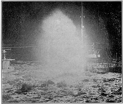
Numerous tests were made, using as high as 30,000-kw. generator capacity, which under the short-circuit conditions of the test delivered 1200 amperes at an initial voltage of 60,000. In no instance was an insulator when equipped with both arcing rings damaged to the slightest extent. Fig. 8 is a night photograph of a 30,000-kw. arc. An insulator with arcing rings, in the midst of the fire, does not show. It was perfectly whole and fairly cool after this experience.
| |||
| Fig. 8. - Night Photograph of A 30,000-Kw. 1200-Ampere Arc on An Insulator Equipped With Arcing Rings. |
A typical case showing the manner in which insulators are destroyed by power arcs is shown in Fig. 13, which depicts an insulator destroyed in service by a power arc following a flashover by lightning.
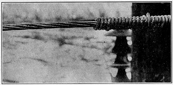
The possible damage to the transmission cable by burning in the event of the upper terminal of the arc traveling out along the cable, owing to wind blowing in the direction of the line was fully dealt with experimentally, with and without arcing rings. It was found that a breeze of 3 miles per hour (estimated) parallel to the line was sufficient to drive the arc out on the cable to a distance of 12 feet in four seconds. This was true whether the insulator was equipped with arcing rings or not. The amount of burning by three successive four-second applications of a 1200-ampere arc is shown by Fig. 9. It will be noted that the cable is not damaged materially at any one place, but that the scarring is distributed. This cable, which is 214,000 cir. mils aluminum, still retains 95 per cent of its original strength.
As to what direction of wind, with reference to the line, will just cause the arc to go out on the cable, it is concluded from test results and observations on lines in service that with sloping ties such as are used on these lines it is necessary that the wind blow at an angle less than 30 degrees to the direction of the line. This value is not materially influenced by the presence of arcing rings.
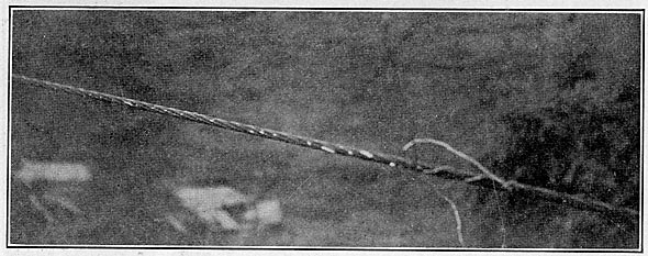
Generally speaking, it is true that the transmission cables are not more exposed to burning with arcing rings than without them, and in neither case is the burning at all serious. Fig. 10 shows a section of cable blistered in service by a short-circuit arc from a generating capacity of approximately 60,000 kw.
| |||
| Fig. 9. - 214,000 Cir. Mils Aluminum Cable Burned by Three Applications of A 1200-Ampere Arc. |
| |||
| Fig. 10. - 214,000 Cir. Mils Aluminum Cable Burned in Service by A Short-Circuit Arc From Six 10,000-Kw Generators. |
The arcing tests outlined above showed considerable latitude in the effective location of the lower ring. In addition, potential tests were made to determine the effect of this ring in various positions upon the flash-over voltage of insulators. It is evidently possible to set the ring high up on and close to the insulator, and thereby materially to decrease the effective insulation, since the initial discharge may pass to the ring, either from some point on the insulator or vertically downward from the cable, instead of passing over the entire insulator to the pin. The extent of this influence not only depends upon the location of the ring, but in a fortunate way upon the condition of the insulator surface. Thus the dry flash-over value may be reduced as desired, to protect against voltages which are apt to puncture the insulator, while the normal minimum wet flash-over voltage need not be reduced. The insulator is thus left to develop its full flash-over value when most needed, and when least likely to result in puncture.
|
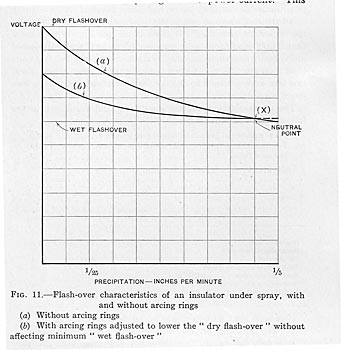
These effects appear graphically in Fig. 11. Curve a represents the ordinary performance of an insulator on a metal pin under spray, the flash-over voltage decreasing with the increase of water. Curve b shows its performance with the arcing ring so proportioned and so placed with reference to the insulator parts as to effect a considerable reduction in the normal dry flash-over voltage, the initial discharge being to the ring instead of to the pin, without reducing the normal minimum wet flashover voltage. Point x designates neutral conditions at which the initial discharge is as likely to strike to the ring as to the pin; at slower precipitation it strikes to the ring, and at higher rates to the pin. Of course, different insulators and different rings give different curves, but in any case it is possible to determine by experiment the size and setting of a ring necessary to accomplish definite results, within certain limits. Comparatively long insulators lend themselves best to such protection, and other things being equal, they need it most.
An important advantage arising from the use of a ring for this purpose, especially on long insulators of the type under consideration, is that the total reduction of voltage is effective on the lower part of the insulator, and relief is given where most needed. Thus it is well known that in an insulator of the pin type, the shell next the pin is subjected to more than its proportion of the total voltage acting. The potential gradient from the top of the grounded metal pin to the tie-wire in the insulator neck is believed to be such as to impose about 50 per cent of the total applied potential upon the pin-piece or inner shell of the insulator under consideration. At dry flash-over, therefore, the inner shell must resist a puncturing e.m.f. of something near 100,000 volts. This excessive potential on the inner shell may be reduced as much as desired by placing the lower arcing ring in proper proximity to the edge of the second or intermediate shell. A definite spark-gap is thus provided in parallel with the lower part of the insulator, insuring the inner shell against puncture and, therefore, in all probability, the entire insulator.
Moreover, when a discharge of short duration occurs from, say the edge of the second shell to the lower ring, it is evident that the resistance of the surface of the insulator above the edge of the second shell is in series with such a discharge and has some deterrent effect upon the passage of the power-current. This is purely an operating advantage. Several cases have been discovered on the lines in service where such action has occurred. It is believed to be infrequent, however, since if an insulator flashes over by lightning, either partially or totally, the power-current is very apt to follow.
In addition to these considerations, the earth potential brought up around the insulator undoubtedly has an effect in ameliorating the puncturing tendencies of high potentials, and provides more favorable electrostatic conditions at times of sudden shock. On this account it was thought that the long three-part insulator would suffer very much less than formerly from breakage of parts by lightning strains, and this has been fully substantiated by experience.
Before the summer or lightning season in 1909 a corrective programme as outlined below had been adopted and executed.
All the insulators on one of the duplicate lines and on some of the important branches, 195 miles in all (see Fig. 1) with more than 11,000 insulators, were removed from the line and subjected individually to a three-minute dry flash-over test of 195,000 volts from a 50-kw. 25-cycle testing transformer. Those which stood this test were returned to the line, and were installed on the two lower wires exclusively.
The results of this test are interesting and are shown in the following tabulation:
Total number of insulators tested (recorded) ...... 10480
Total number failed by puncture of one or more parts .. 4172
Per cent failed ................... 39.5
Individual parts failed as follows:
|
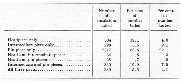
It is seen that 81.6 per cent of all failures involved the pin-piece, and that 55.5 per cent involved the pin-piece only.
It is only fair to say that these dry flash-over tests are very much in excess of any requirements which were anticipated at the time of the manufacture of these insulators. Had they been tested complete before their first installation, it would have been at a voltage certainly not in excess of 150,000, which is at present considered fairly high for a three-part 60,000-volt insulator. Prior to inaugurating flash-over tests on insulators from the line, some 2,000 insulators in stock were tested to 150,000 volts, 3 minutes, resulting in a loss of 7 per cent, which cannot be considered excessive for an insulator of this shape.
On the top wire where most damage by lightning had occurred in the past, and on the lower wires to the extent necessary to accomplish their insulation, a new type of insulator, shown in Fig. 12, was installed. This is a four-part insulator of about the same outside diameter as the old style three-part insulator, but considerably shorter, 6 inches in fact. It flashes over dry at 190,000 volts, and wet at 105,000 volts. The individual parts and the assembled insulators were tested to dry flash-over voltage for 3 minutes. There was a loss of 3 per cent of assembled insulators by this test.
| |||
| Fig. 12. - New Style Four-Part Insulator Installed on Top Wire, 1909. Also Shows Method of Attaching Arcing-Ring Supports to Cylindrical Pins. |
An insulator of this design was selected in the light of experience, which clearly indicated that long insulator parts can ill resist the mechanical stress of lightning shocks, and that three thicknesses of porcelain are not sufficient safely to resist puncture in insulators having high flash-over characteristics. Moreover, short shells allow sufficient creepage at high voltage to effect a more nearly uniform distribution of potential upon the several parts, which prevents the puncture of any single shell by a disproportionate division of potential. In short, this four-part insulator was designed to flash over rather than to puncture, and to do this with some margin of safety against puncture.
Lower arcing rings were installed on all insulators in such a manner that relief occurs at a maximum of 160,000 volts, and also in such a manner that wet flash-over values are not reduced. The maximum puncturing potential is thereby limited to approximately 30,000 volts less than the actual voltage which all insulators withstood under test, thus effecting a fair margin of safety against puncture. This result is accomplished by the use of a 26-in. by 3/8-in. iron ring, located approximately 22 in. above the base of the three-part, and 2 in. below the base of the four-part insulators. It was thought that this relief was desirable for the three-part insulator, since practically the entire 30,000-volt reduction tends to relieve the inner shell, the one most liable to puncture. While not considered necessary for the four-part insulator it is not objectionable, and gives the advantage that the lower arcing ring is in a better location, to attract the power arc, since this insulator is, comparatively speaking, a very short one.
Upper arcing rings were not installed until late in the season, after experience had shown them to be necessary. The second line was not tested or protected in any way.
Since both lines are on the same right-of-way for a considerable distance, and in general pass through the same section of country, being at most a few miles apart, a definite comparison of the operation of the two lines for the lightning season of 1909 shows the value and effectiveness of the reinsulation and arcing ring protection. Also a comparison of these results with those of former years is of interest. It is to be remarked that the line selected for reinsulation is, when on a separate right-of-way, the southerly one, and apparently lies more in the usual path of electric storms than the one which was not reinsulated.
Table I is a comparison of lightning effects on reinsulated and non-reinsulated lines during 1909.
Item 1 shows that one insulator was disabled on the reinsulated lines against 54 disabled on the non-reinsulated lines. Fig. 13 pictures the one insulator lost on the reinsulated line. This is a clear case of breakage by power arc, after flashing over by lightning. It occurred early in the year, before inspection of the work had been made. This failure was due to improper installation of insulator and ring. The 54 insulators disabled on the non-reinsulated lines were destroyed in the same way as were those lost in former years, viz., shattered by lightning, shattered by power arc and punctured.
|
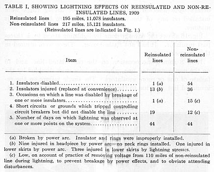
Item 2 shows that 13 insulators were injured on the reinsulated lines. A careful inspection of these lines was made after lightning storms to determine the exact performance of the arcing rings, and to learn whether or not their location was such as to give the desired results. The results of this inspection are as follows:
|
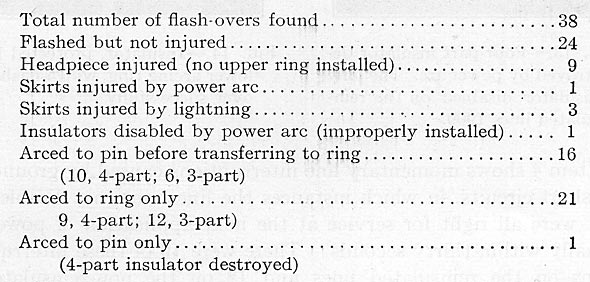
No insulator was punctured either totally or in any of its parts.
| |||
| Fig. 13. - Four-Part Insulator Destroyed by Power Arc. the Only Insulator Disabled on the Reinsulated Lines 1909. |
| |||
| Fig. 14. - Insulator, Protected by Lower Arcing Ring, Which Flashed Over Successfully. |
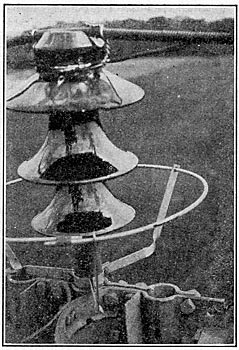
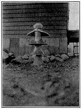
Fig. 14 shows an insulator, protected by a lower arcing ring, which flashed over successfully.
Fig. 15 pictures an insulator, the headpiece of which was broken by a power arc, burning the tie-wire in two. Eight others were affected similarly. No upper arcing rings were installed on any of the insulators which were broken in this manner.
Fig. 16 shows the damage done by lightning stress to a three-part insulator. It had not flashed over. Three were injured in this manner.
| |||
| Fig. 15. - Insulator Injured in Head-Piece by Power Arc. No Upper Arcing Ring Was Installed. |
| |||
| Fig. 16. - Insulator With Second Shell Injured by Lightning Shock. |
Item 3 shows one occasion on the reinsulated line, and 15 on the non-reinsulated line, when the lines were disabled by the failure of one or more insulators. The single failure on the re-insulated line was due to the one insulator appearing in Item 1.
Item 4 shows momentary line interruptions caused by grounds or short-circuits, in which instances the lines were not disabled, but were all right for service at the next application of power, usually within thirty seconds. There were 19 of these interruptions on the reinsulated lines and 12 on the non-reinsulated lines. The fact that there were fewer on the non-reinsulated lines is believed to be due to the operating practice of removing voltage from more than a hundred miles of non-reinsulated line during the known progress of lightning storms in the vicinity of the lines. This was done to obviate damage by power arcs, and to prevent attending disturbances to the system. It is interesting to note that this section of non-reinsulated line was disabled twice while no voltage was on it.
Considering Item 4 in conjunction with the results of line inspection mentioned above, it is evident that the lower arcing ring is not close enough to reduce the degree of insulation of the line under the average conditions of moisture during lightning storms. This is shown by the slight difference in the number of the momentary interruptions on the two lines, and by the fact that on the reinsulated lines in about half the instances the initial discharge was to the insulator pin, and in about half to the arcing ring. At the same time all puncturing of insulators has been eliminated. For these reasons it is believed that the rings have been placed so as to operate as originally intended.
Item 5 shows the number of days on which lightning was observed at one or more points on the system. This item is interesting in connection with Tables II and III.
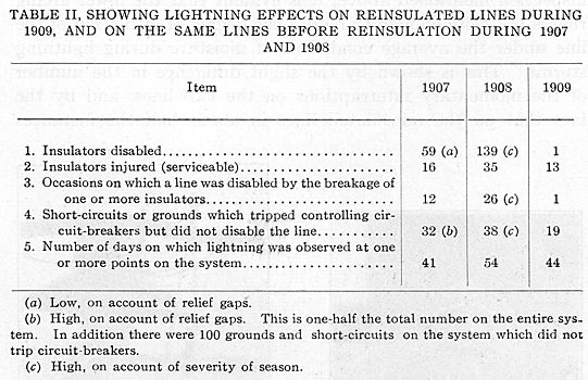
Table II is a comparison of lightning effects on the reinsulated lines during 1909, and on the same lines previous to reinsulation during the years 1907 and 1908.
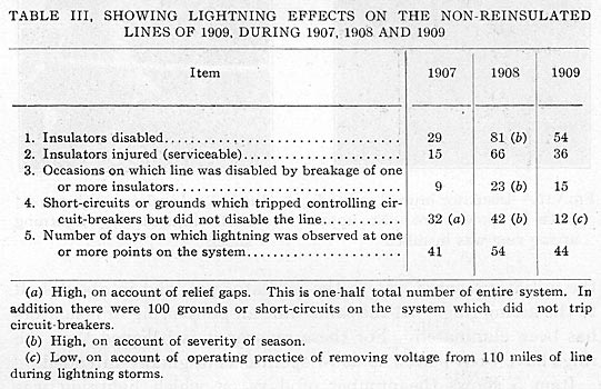
Table III is a comparison of the lightning effects on the non?reinsulated lines of 1909 and on the same lines in 1907 and 1908. These tables are self explanatory. Attention is called to the extra severity of the lightning season of 1908, and to the fact that the lines which were reinsulated in 1909 had formerly received rougher treatment than had the other lines.
From Table III it appears that lightning effects in 1909 were slightly more than half those in 1908, and somewhat in excess of those in 1907. It is therefore believed that the reinsulated lines have been subjected to a lightning season of average intensity.
|
|
Concrete instances may be cited which show definitely that protected insulators have withstood severe lightning. In sections where the lines are 26 ft apart on the same right-of-way, insulators were destroyed on the unprotected line in quantities, and in a manner which indicated extraordinary lightning severity. On the protected line in the same locality insulators flashed over uninjured. On six known occasions all the insulators on a structure discharged, and on six other occasions two insulators per structure were involved. Of the 38 protected insulators which are known to have been affected. 21 were on the lower wires. These results are all indicative of severe lightning effects.
This experience with sound insulators protected by arcing rings justifies the feeling that extended interruptions due to line breakdowns by lightning will be very rare in the future, if they do not entirely disappear. Prevention of occasional momentary disturbances, caused by the discharge of one or more conductors to ground from the effects of lightning, is believed to be impossible, since potentials exist at times which are too great to be insulated, and too severely localized to be relieved by lightning arresters at a distance. Duplication or multiplication of circuits controlled by proper automatic sectionalizing apparatus tends to prevent such interruptions from reaching the service.
Virtually no experience has been had with arcing rings on untested insulators. The work of applying them on the remainder of the system, omitting the testing of insulators, is in progress at present. In view of the material protection against puncture which the lower ring affords to the pin-piece of the three-part insulator, which piece, as, the testing of 11,000 of these insulators shows, is the one most liable to puncture, and which if saved will probably result in saving the entire insulator, satisfactory results are anticipated.
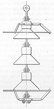
| |||
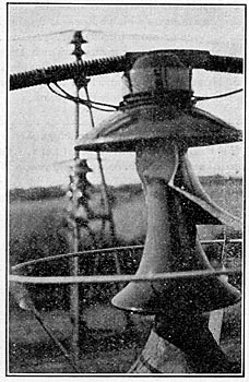
| Fig. 17. - Arcing Rings Applied to A Suspension Type Insulator. |
Before undertaking the rather expensive experiment of reinsulating its lines and equipping them with arcing rings, the company sent representatives to various transmission plants in the United States and Canada to inquire about line troubles in general, and particularly regarding the effectiveness of overhead grounded conductors. The result of this investigation was not altogether favorable to the overhead ground wire. Various opinions were obtained expressing its usefulness and its uselessness. No plant comparable in extent and type of construction with the one under consideration was discovered which did not have to contend with the shattering and puncturing of insulators by lightning, as well as with occasional short-circuits during lightning storms. Considering the heavy expense of properly installing an overhead grounded conductor, and the extra load it would impose on the line structures, together with a large element of uncertainty as to its efficacy, the idea of installing one was abandoned.
While intentionally designed to protect insulators mounted on grounded metal pins it is believed that grounded rings would be beneficial to insulators on wooden pins also.
In view of the extensive use of suspension insulators, some experimental work has been carried on which indicates the necessity for, and effectiveness of, arcing ring protection on this type of insulator. The arrangement shown in Fig. 17 apparently accomplishes the desired results.
