[Trade Journal]
Publication: Electrical World
New York, NY, United States
vol. 50, no. 6, p. 277-281, col. 1-2
Kern River No. I Power Plant of the Edison Electric Company, Los AngelesI.
THE Pacific Coast, California in particular, has won a goodly amount of renown in engineering circles because of its many noteworthy hydroelectric power plants and long-distance transmission systems. Harking back 14 years to the noted historical work at Redlands and Pomona, practically all the improvements in hydraulic design in connection with high-head plants that have stood the test of time and which mark the best practice of to-day have been evolved in connection with the California water-power plants. Substantially the same may be said regarding transmission work; and, although the record for highest voltage has been surpassed quite recently in Michigan, the Golden State still operates successfully the longest lines on the continent.
With this excellent record of pioneer work, and with many modern efficient plants now in continuous operation, it is interesting to note the improvements or innovations incorporated is the design of any new plant.
The Edison Electric Company, of Los Angeles, has just completed and placed in operation a power plant on Kern River, which, while not surpassing any previous records of high heads utilized or length of transmission, does embody in its construction many distinguishing features, some of which are pronounced departures from previous practice.
| |||
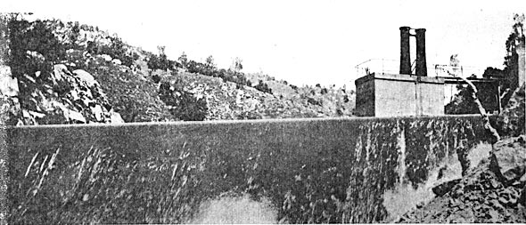
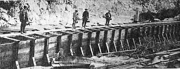
| Fig. 1. Concrete Division Dam and Head Works for Drainage Tunnel. |
In capacity, the Kern River No. 1 power plant equals the rated capacity, 20,000 kilowatts, of the largest impulse-wheel plant previously in operation, and in overload capacity surpasses it. Its gravity conduit, constructed almost entirely of tunnels excavated through the mountains, is the most permanent and costly hydraulic waterway in the country. The pressure main, driven in the form of a tunnel, down the mountain slope is probably the most unique feature of the installation and is a decided innovation in power-want construction. The water wheels embody new features in the design of buckets, nozzles and governors. In the electrical details of the station is incorporated the most modern apparatus. The transmission line is at present operating at 60,000 volts, which will later be raised to 75,000 volts. The length of transmission, 117 miles, is exceeded in only a few instances. Moreover, the steel towers and insulators are of special design.
Considered in entirety, or as to its several conspicuous component parts individually, the Kern River No. 1 station of the Edison Electric Company typifies the latest modern practice in hydroelectric power plant design, and makes timely the following descriptive data. General descriptions of this plant as under construction at that time, as well as the other power plants and general transmission and distribution system of the Edison Electric Company in southern California, were given in the ELECTRICAL WORLD AND ENGINEER of Feb. 25, March 4, 11 and 25, and April 8, 1905. The present article is intended to supplement and bring those descriptions up to date.
GENERAL DESCRIPTION.
The Kern River is, the southernmost large tributary of the San Joaquin River, and has its head in the snow-covered slopes of Mt. Whitney and neighboring peaks in the Sierra Nevada Mountains.
Water for the Kern River No. 1 plant is diverted at a point about one-half mile below Democrat Spring, in Kern County, and about 14 miles up the river from the mouth of the canyon. A hydraulic conduit, consisting almost entirely of a series of tunnels, approximately nine miles in length, conveys the water through the mountains on the south side of the river to a forebay at a point about 900 feet above the river, and about two miles from the mouth of the canyon, where the plant of the Power Transit & Light Company, of Bakersfield, is located.
From the forebay the force main continues down to the power house in an inclined tunnel. The power house is located on the bank of the river directly opposite the intake of the Bakersfield. plant, and at an elevation of about 20 ft. above the ordinary high-water level of the stream at that point. The tail race of the station is designed so as to deliver the water to the river immediately above the diversion point of the Bakersfield plant.
The transmission circuits extend along the Kern Canyon and cross country to Los Angeles, 117 miles distant.
DIVERTING DAM.
The dam which is built to divert the water from the Kern River into the hydraulic conduit is placed on bed rock and is carried up to a point 1.25 ft. above the flow line in the tunnel conduit, thus insuring a constant supply as long as the reservoir created by the dam is kept filled. In excavating for the dam, bed rock was found to exist at varying depths, the deepest portion being at the south end at about 35 ft. below the stream bed. A coffer dam was built to divert the river during the construction and while the fill overlying the bed rock was being excavated. Trenches were then cut in the bed rock and holes bored in which steel bars were driven in two rows across the canyon. The first layers of concrete were placed on the bed rock and secured to it by means of the trenches and the steel bars. Cyclopean concrete was 'the material of construction, the rock used being the granite found in the canyon. Many of the blocks were of large size, some weighing several tons each. About 1500 cu. yards of material were placed in the foundation and 3500 cu. yards in the dam proper.
The dam is of the overflow type as shown in Figs. 1, 4 and 5. Its length on the crest is 203.56 ft. and its height above ordinary water level in the river about 20 ft. At the base in the thickest part it is 52.81 ft. wide. The crest has a small angle with the horizontal, and is 7 ft. in width. The crest and lower face were designed so as to give a true hydraulic curve to the water overflowing, and to attain this end the upper 15 ft. of the face was built with a batter of 1 to 1 so as to allow an air space under the water. The theory of the design is that air will enter this space under, the water from the ends of the dam and that enough will be carried down with the water to form an air cushion. With from 2 ft. to 3 ft. of water flowing over the dam a very smooth surface is presented. Below the 45 degree batter the down stream face has a radius of 100 ft. The up-stream face has a batter of three-quarter inch to the foot.
HEAD WORKS.
The head or diversion works of the gravity conduit consist of an enlarged or widened section of the intake tunnel with controlling gates operated by means of hydraulic cylinders. In order to prevent contraction as the water enters and to afford sufficient screen area to admit the water, the tunnel is widened out at the entrance to 16 ft. 6 ins. The screens or grizzlies are made of slanting bars and extend both in front and on the side of the controlling gates. The bars are 1/2 in. x 3 in. and are spaced on edge 3 ins. between centers, by means of 2 1/4-in. thimbles, the thimble rods being 4 ft. apart. The screen is 20 ft. long on the slant and 8 ft. high and is supported on 4-in. cast-iron pillars.
| |||
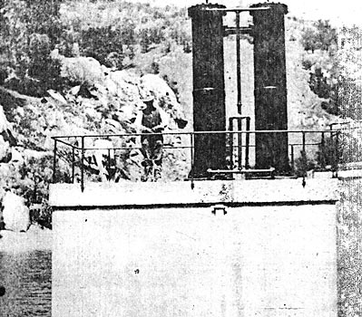
| Fig. 2. Hydraulic Cylinders for Operating Intake Gates. |
Behind the screen and just above the gate is a 10-ft platform on to which can be raked any detritus caught by the screen. The grade at the entrance of the diverting tunnel is increased above the normal grade so as to accelerate the water from its state of rest above the intake to normal velocity in the tunnel below.
Another important feature of the head works is the drainage or sluicing tunnel, 365 ft. in length, that is driven through bed rock below the intake at the south end of the dam, penetrating to the bottom of the reservoir above the diverting dam. A heavy grizzly, built of 70-lb. T-rails, protects the entrance of this tunnel, and behind are two gates operated by hydraulic cylinders, by means of which the tunnel can be closed or opened as desired. The drainage tunnel was first used to divert the water from above the site of-the slam during its construction to the river at a point some distance below the headworks. Its permanent purpose will be to sluice out, at such intervals as may be necessary, any silt accumulating in the reservoir above the dam. The gates of this drainage tunnel are constructed for operating under a pressure corresponding to from 35 ft. to 45 ft. depending on the quantity of water flowing over the dam, the hydraulic cylinders for the gates being designed to move them under a head of 20 ft. of water over the dam, should a flood of this magnitude ever occur.
| |||
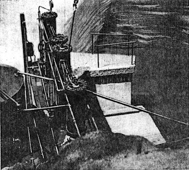
| Fig. 3. Hydraulic Cylinders for Operating Gates for Drainage Tunnel. |
Each of the gate openings is 8 ft. 10 1/4 in. high and 3 ft. 8 in. wide, the side frames being of cast iron, and the sill a 10 in. x 10 3/4 in. redwood timber. The gates are built up of 5/16-in. steel plate and 6-in. 15-lb. I-beams, the sides being formed of 12-in. I-beams. There are two cast-iron hydraulic cylinders installed in each gate. The set for the east gate is mounted on top of the concrete operating shaft, the west set being placed directly below as there was not sufficient lateral space to place them both on the same level. The lower cylinders are placed 38 ft. 8 in. above the sill of the gate and operate their gate by lifting rods 26 ft. long. The upper cylinders operate their gate by means of 40-ft. rods. These lifting rods are 4 1/2 ins. in diameter, and are made of wrought iron incased in brass tubing to prevent rusting. The gates are guided at each side by four bronze rollers 3 ins. in diameter. In order to equalize the pull of the two cylinders on each gate there are installed two racks to ft. long and 6 ins. wide into which mesh two 12-in. pinions mounted on the top of the gate.
The gates for the intake tunnel are similarly constructed. The hydraulic cylinders, both for the intake gates and the sluice gates in the drainage tunnel, are operated by means of oil pressure supplied by gravity from a tank on the bank. The oil discharged from the cylinders is pumped up to this tank by a triplex pump, electrically driven, a sufficiently powerful land pump being installed for emergency use.
TUNNELS.
The hydraulic conduit of the Kern River plant is noteworthy by reason of its being the most permanent construction of its character in the country. The Edison Electric Company after its 14 years' practical experience with the construction and operation of hydroelectric power plants has profited by the knowledge gained of the different forms of conduit used, s eh as timber flumes, earthen ditches, concrete-lined ditches, cement pipe and tunnels, and for its Kern River work determined that the most efficient, and, in the long run, economical construction would be a system of concrete-lined tunnels. The expense of driving the tunnels was a large item, but it was warranted in this instance because of the large quantity of water handled and by reason of its permanency and the fact that it will be subject to practically no depreciation losses and but little expense for maintenance. Another important feature of the tunnel construction is that there will be practically no evaporation loss from tke conduit. As the evaporation from the natural stream of the Kern River is estimated to be from 15 to 20 per cent, when the water is low during the summer months, this factor will be an important one during periods of minimum flow. Another advantage of the closed conduit is that no leaves, sticks or other debris can enter the water after it leaves the headworks.
 |
| Fig. 4. Plan of Diverting Dam and Intake |
Between the intake and the forebay there are 19 tunnels forming approximately eight units of gravity conduit. The number and length of these tunnels are given in the following table:
 |
The tunnels are numbered from the intake down, Tunnel No. 1 being the intake tunnel, the entrance to which has already been described.
The tunnels were excavated in the rough to be 9 ft in width and 7 1/2 ft. from the bottom to the spring line of the arch, and 9 ft. in height in the center. Afterwards they were lined with concrete 6 ins, to 10 ins. thick on each side and the floor paved with 3 ins. of concrete, the net section thus obtained being 8 ft. in width by 7 ft. in height. The entire surface of the side and floor was covered with a cement mortar-plaster 1/4 in. thick, composed of one part of cement to two parts of sand. At the corners of the walls and floor a curve with a 3-in. radius was formed in order to prevent wear at that point and also to smooth up the flow of water.
 |
| Fig. 5. Section of Dam |
The section of tunnel adopted is not the most favorable to give the highest velocity on a minimum slope, but is the most advantageous for the purpose, as by making a wider tunnel greater difficulties wound have been encountered with the roof of the tunnel where it passed through loose or shattered formation. The grade of the tunnels is 7.92 ft. per mile, it being intended that the water should be carried at a depth of 6 1/2 ft. The cross-sectional area of the stream is, therefore, 52 sq. ft., the wetted perimeter is 21 ft. and the mean hydraulic radius 2.5. Assuming the coefficient of roughness to be 0.012 in Kutter's formula, the conduit has a discharge capacity of approximately 470 cu. ft. per second. Experiments made on other tunnels of the company indicated that the coefficient would be about the value stated for this particular conduit. Observations made during the first few days after the conduit was placed in service showed that the coefficient is even less than 0.012.
| |||
| Fig. 6. Section of Timber Flume Connecting Tunnels 1 and 2. |
In places where the tunnels pass through seamy and shattered formation or "blocky" ground, they had to be arched overhead in order to support the roof, the concrete at the center of the arch being from 12 ins. to 18 ins. thick. Less than Is per cent of the length of the tunnel required such overhead arching. Where this was necessary, it was placed by using a template, with lagging overhead, the concrete being thrown back and tamped into place above the lagging. In excavating through this blocky ground, timbering was necessary, the standard bent being formed of 6 in. x 8 in. sets, spaced 4 ft. between centers and holding the rock back by 3-in. planks. In such sections the timbers were left in position and completely covered by concrete.
| |||
| Fig. 7. Portal of Tunnel No. 19. |
The concrete at the sides was tamped into place behind boards supported by vertical forms. Wherever large cavities had been blasted out in driving the tunnels, they were filled with backfill of riprap, the interstices of which were filled with sand and gravel. The same method was pursued above the concrete in the arches. Consequently there are no cavities existing between the bed rock and the concrete lining in the tunnels.
| |||
| Fig. 8. Manhole Between Tunnels Nos. 17 and 19. |

In several places springs were encountered and as the pressure that would be created by stopping them up might be disastrous to the tunnel lining, vents were installed through which the water can flow into the tunnel. These vents consist of sections of pipe from 3/4 in. to 3 ins. in diameter and 6 in. to 8 ins. long, set in the floor or wall and left open at both ends. The water being under higher pressure than that flowing in the tunnel, continues to flow into the tunnel and thus relieves it of any strain.
 |
| Fig. 9. Timber Flume, 32-Ft Span. |
The excavation of each of the 19 tunnels was carried on from both ends, thus dividing the work up among 38 headings. The work was principally done by pneumatic drills with 3 1/4-in. cylinders. Some hand work was done in opening up approaches and adits and where loose formation was encountered. The ordinary progress in driving with pneumatic drills was 5 ft. for a ten-hour shift using two machines in the face. This varied considerably, however, as the number of holes required for breaking the ground varied from 10 to 24. The depth of the holes usually employed was as follows:
 |
The amount of energy consumed also varied according to the formation, so that no stated quantity per round of holes can be relied upon. In the toughest rock encountered, it was sometimes found necessary to reload the holes the second time in order to break the ground, the first blast blowing out the rock at only the upper end of the holes.
The pneumatic drills were supplied with compressed air through 3-in. and 4-in. steel casing laid from the six construction camps located at suitable points along the canyon between the power house and the intake. Ventilation was pro vided by means of motor-driven Root reversible blowers located at the tunnel or adit openings and connected with the working faces by means of galvanized iron stove pipe. Other details of the tunnel construction may be found in the ELECTRICAL WORLD Of March 11, 1905.
The Edison Electric Company carried on all the tunnel excavation work itself, the only contract work being that of teaming, the supply of provisions and feeding the men. By this method the company has been able to secure construction data which will be invaluable to it in carrying on similar work in the future and in the consideration of contract work.
The only contract work done on the tunnels of the Kern River No. 1 plant was for the concrete lining. This was done by Glass & Fischer, of Los Angeles and Redlands, this firm also contracting for the boarding houses. Standard and Colton brands of Portland cement, supplied by the two California manufactories, were used throughout for the concrete, the mixture being in the proportion of 1, 3 and 5. For the sand and aggregate, the granite excavated from the tunnels was used. The rock was crushed to 1 1/2-in. and 2-in. size and for the sand was crushed and rolled so as to pass through a 60 screen. Gates gyratory and Blake jaw crushers and Buchanan 10-in. rolls were employed. As no adequate water supplies were available along the route of the conduit, the water necessary for mixing the concrete had to be pumped up from the river, Rumsey triplex pumps being employed for that purpose. For mixing, one Smith and two Ransome mixers were used. The men worked on two nine-hour shifts, illumination being furnished by a construction power plant, to be mentioned later. A total of 110,000 ft. of lumber was used for forms on the concrete work.
After the tracks bad been removed from the lower tunnels and when the roads to the upper camps were impassable because of heavy rains and snow, two automobile wagons proved indispensable in carrying cement and other supplies through the finished tunnels from Camp I to the upper tunnels. About 7000 bags of cement were thus transferred from Camp 1, an average distance of 5 1/2 miles. In all about a million pounds of freight was carried by the two machines. Even the steel rails of the construction track were carried out on the automobiles. With light loads a speed of about 18 miles an hour could be made, precautions being taken at curves, which were indicated by white signal flags.
After the tunnels were completed two two-wheeled hand carts with rubber-tired wheels were used for carrying cement and light tools for such finishing and repair work as was necessary. They were also brought into service in stringing the telephone line that is carried throughout the entire tunnel connecting the power house with the diversion works at the dam. The two galvanized-iron wires of this telephone line are carried on inverted T-shaped brackets about to ins. from the roof of the tunnel. The brackets are formed of pipe with porcelain insulators bolted on each end of the horizontal arm. The vertical pipe is secured in the holes of the rock or cement by wooden plugs.
TIMBER FLUMES.
The tunnel work was planned so as to avoid wherever possible flumes for spanning the side ravines encountered along the line. However, in order to maintain a good alignment and make the line as short as possible, a few exceptions had to be made to this rule. Some of these side ravines leading down to the main canyon and crossing the line of the conduit were on such a flat slope that should the tunnel be constructed under the ravines, the necessary adits would have been very long. This not only would have increased the cost materially, but also would have added to the length of the line, and the time required to do the work. At such points where there was no danger from falling rocks the ravines were spanned with flumes. There are six of these flumes, the number and length of which are given in the following table:
 |
All are constructed of timber except No. 3, which is built of reinforced concrete with a steel frame.
Fig. 6 shows the method of constructing the timber flumes. They are placed on concrete foundations and are designed with a factor of safety sufficient to make their life from 3o to 40 years. The framework for supporting the flume box is of Oregon pine, being so designed and distributed that no part of the timber comes in contact with the earth or is exposed to the drip should the flume at any time spring a leak. In this way the life of the Oregon pine will be great, as it is invariably kept dry and free from contact with the soil.
The flume box is built up of 3-in. x 12-in. planks of redwood grown in swamp lands west of the Coast Range in northern California. The grade of this lumber is perfectly clear, and its quality is such that its life should not be less than 40 years. The edges of all planks were beveled so as to give a quarter inch opening on the inside of the joint, which is caulked with ship chandler's oakum. The bottom seams were covered with hot asphaltum and 1-in. x 6-in. redwood battens were nailed down over them.
On the sides of these flumes a specially designed batten is used. This batten, is of x 6-in. redwood, the upper half being cut away on a curve, permitting asphaltum to be poured between the batten; and the side of the flume. At the corners of the flumes a quarter-round strip is nailed.
The design of the flume above described has been thoroughly tested and even if it should remain /dry for months in the hottest weather, its designers state that it may again be filled with water without having any perceptible leakage.
In some cases where crossing streams that are apt to carry considerable water in winter, span flumes are constructed. Fig. 9 shows a 32-ft. span built with a 10 in. x 12 in. timber frame and resting on 12 in. x 12 in. beams.
In connecting the wooden flume with the portal of a tunnel use was made of a construction of a special nature, which offers two points of contact between the wood and the concrete, and a well between the two, from which the water may be pumped out, and any leaks repaired should these ever occur between the wood and the concrete.
