[Trade Journal]
Publication: Electrical World
New York, NY, United States
vol. 50, no. 9, p. 401-2, col. 1-2
Kern River No. 1 Power Plant of the Edison
Electric Company, Los Angeles IV.
TOWERS.
THE transmission line is carried on galvanized steel towers, there being 1140 of these towers. The tower heights range from 30 ft. to 60 ft. They are uniformly constructed of galvanized angle iron, bolted with galvanized bolts and held in shape by means of tension rods. There are no compressive braces except one pair in the upper portions of the sides, and between the cross-arms. The nine insulators are spaced on 6 ft. centers, five on the upper arm and four on the lower, the arms consisting of 9-in. 13-1/4-lb. channels.
All portions of the tower are figured to be safe under a wind pressure of 30 lbs. per square foot on the tower and the wire of a 700-ft. span. The towers will also withstand absolute failure of any single wire, even though none of the resulting strain is transmitted to adjacent wires.
Fig. 31 illustrates the construction of a standard 60-ft. tower, which is 12 ft. wide and 12 ft. across at the base. The uprights are formed of 4-in. angles and the cross braces of 2-3/4-in., 3-in. and 3-1/2-in. angles, the diagonal rods being 11/16 in. and 5/8 in. in diameter. Four insulators for the telephone lines are mounted on the third cross-bar, 21 ft. above the ground. Forty of the towers were made extra heavy for use at points where the line changed its direction.
 |
| Fig. 31. - 60-Ft. Transmission-Line Tower. |
The foot plates of the towers are of cast iron, dipped in asphalt, and 24 in. in diameter. They are attached at the bottom to 4 in. x 4 in. foot posts, which are asphalted on top of the galvanizing. These posts are bolted as extensions to the corner posts of the tower, and set in the ground a depth of 6 ft. Tapered holes were dug for these foot plates and the earth was tamped back on them very carefully. No concrete footings were used, except on some special work in the city of Los Angeles, where a great many of the tower heights exceeded 60 ft. The tower parts were made as light as was consistent with rigid construction. Under the extreme conditions mentioned above the factor of safety in any steel member is specified to be not less than two and one-half.
| |||
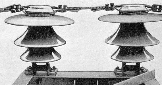
| Fig. 32. - Double Insulator on Tower, Showing Method of Tying. |
No cast iron was permitted in the construction, except in the foot plates. All connections are made with malleable iron castings with a factor of safety of 4. The insulator pins are of cast-steel and were furnished as a part of the tower. They are secured to the tower by four bolts and are cemented into the insulators. The towers and insulator pins were furnished by the U. S. Wind Engine & Pump Company, of Batavia, Ill.
| |||
| Figs. 33 and 34. - Standard 60-Ft. Tower and A Special 60-Ft. Tower Near San Fernando Switching Station. |
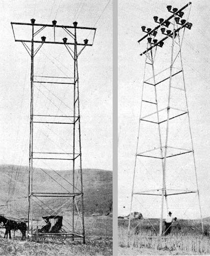
The towers were shipped from the factory knocked down with their small parts boxed and were hauled to their respective locations by wagon. They were assembled lying on the ground and "kicked" into place by means of a gin pole. This method of erection was found to be very satisfactory for all sizes of towers, and only such towers as were located in rugged or inaccessible country were built up piece by piece.
In stringing out the wire, teams were used with usually four animals, although in limited spaces two horses on a tackle were substituted. Wherever possible, those wires which could be lifted on to the tower were strung out alongside and later on thrown into place.
LINE CONSTRUCTION.
The transmission line is designed to consist of three circuits with the wiring spaced symmetrically on 6-ft. centers. This wire is seven-strand, 4/o hard-drawn copper, having an elastic limit exceeding 35,000 lbs. total, and an ultimate strength of 62,400 lbs. It was furnished by J. A. Roebling's Sons Company, National Conduit & Cable Company and American Electrical Works. About two and one-half million pounds of cable was used on the line.
The wire was sampled and tested at the mill before being accepted. It was greased and shipped to the purchaser on reels containing usually two 4000-ft. lengths. Some wire was also purchased in shorter lengths for convenient use in the mountain section. No special difficulty was, however, experienced in handling full-length pieces even in the most rugged country.
Before the line was designed, a large amount of experimenting was done by the Edison Company's engineers on a special thousand-foot span erected at Declez and equipped with a dynamometer and recording thermometer to obtain continuous readings of the variation in stress with changes of temperature and wind velocity. Curves showing the relation of the observed points to the calculated curve were then plotted. curves for aluminum were also prepared, the results used being those obtained by the Pittsburg Reduction Company on the line which it erected some years ago near its factory. From a comparison of these curves, it was evident that the calculation formulas were sufficiently accurate for commercial use, including all effect from elasticity, closure of strands upon themselves under increase of stress, and the slight difference in loading upon the different strands due to the center strand being straight while the others are spiraled about it and consequently have a somewhat greater length. From the formula, a conveniently arranged sag-temperature tabulation was made out and was supplied to the line-foreman in this form. These experiments were carried out under the supervision of Mr. R. J. C. Wood, acting electrical engineer for the Edison Electric Company. For convenience in checking the construction work, Mr. Wood made the- slide rule illustrated in Fig. 35. By setting the required span at the index at the left, the sag will be read opposite the temperature chosen. For example, the illustration shows the scale set for a 900-ft. span, which gives a 27-ft. sag for copper at 50 deg. F. The scale is calculated for No. 0000 seven-strand copper and 344,000 c. m. 19-strand aluminum, with a maximum stress of 22,000 in copper and 10,000 in aluminum at 30 degs. F. in a 30-lb. wind.
As only six conductors were strung for the present line, it was desirable to leave the easiest circuits to he pulled in later. The threading of three cables through the tower was, therefore, desirable at this time. These were carried across rollers bolted to the arm, as were also the upper wires during tying in.
 |
| Fig. 36. - Section of Insulator. |
The type of clamp used is shown in Fig. 36. It is 2 ins. long, and is constructed of three pieces, the inner piece being shaped to conform to the two wires. The tic wires passing around the neck of the insulator are of No. 1 copper strand. The four-bolt clamps are of brass, while the U-piece placed in the top of the insulator to prevent chafing is of No. 24 copper. The tie wires fail in test at about 4000 lbs. The clamps will withstand somewhat more, and the construction could readily have been made much stronger at a slight additional expense if it had been considered desirable.
The insulators used on the Kern River transmission line are the largest yet made for commercial transmission purposes. Insulators of a greater diameter have been constructed and are in use elsewhere for special purposes, but none so large have been made for a long-distance transmission system. The Kern River insulators are 18 ins. high and 8 ins. in diameter at the grooved top. The top section is 18 ins. in diameter and the two lower petticoats are, respectively, 14 ins. and 11 ins. in diameter. Each assembled insulator weighs 50 lbs. The main contract, for 7500 insulators, or over 90 per cent of the total number, was placed with the Locke Insulator Manufacturing Company, and the specifications called for a glaze that would match the galvanized steel towers. The manufacturers were successful in producing an insulator with a light gray or slate-colored glaze which harmonizes very well with the hue of the towers. The resulting construction is comparatively inconspicuous on the transmission line and the insulators, being of this neutral shade, do not afford as prominent a target for malicious marksmen as do those of the ordinary brown glaze.
The insulators were all carefully tested at the factory by one of the Edison Company's engineers. The specifications called for a guarantee of a 100,000-volt test from the groove to the pin for half an hour under a precipitation of 1 in. in five minutes at an angle of 30 deg. from the vertical. The assembled insulator was required to withstand under a wet test a potential of 150,000 volts for 30 seconds, and the separate parts are guaranteed to withstand a voltage of 25 per cent in excess of the normal proportion of over-voltage test. A small quantity of brown insulators are used, they being supplied by the Thomas and Knowles factories.
The insulators are guaranteed to withstand a side strain of 4000 lbs. and actually fail at approximately 9000 lbs. The wire has an ultimate strength of 61,300, but its elastic limit, as noted above, will not much exceed 35,000. The normal failing point of the ties, 4000 lbs., is, therefore, sufficiently high for safe construction, while they are not so strong as to stand more than the wire or the insulators.
The transmission line, as stated elsewhere, is carried on spans as long as the character of the country would permit with towers not exceeding 60 ft. in height. This maximum height was determined upon as being that which would give the lowest total cost of construction. The sags for the different spans being determined, as stated above, and the telephone clearances from transmission wires being assumed at a minimum of 7 ft., it was necessary to determine the tower spacings with minimum safe ground clearances in the different portions of the line. In order to do this accurately, survey parties were sent over the entire line, taking tower locations, and determining all elevations so that they were able to plot a profile of the transmission system showing the elevation of each tower, the height of the intermediate elevations and the important topography of the country. The parties designated the height of the tower while in the field, making their profile as they went along and checking the resulting line before leaving that section of the country. What changes have been made from these locations have been due entirely to causes other than incorrect location for clearance.
| |||
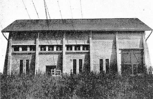
| Fig. 37. - San Francisco Sub-Station. |
A telephone circuit is carried the entire length of the transmission line, being supported on the towers about 20 ft. above the ground. Between towers the wires are held up by wooden poles, two poles being necessary between towers for an average 700-ft. span.
SWITCHING STATIONS.
The transmission lines are carried through from one end to the other with transpositions only at switching stations. There are at present only three such buildings, at Tejon, Castaic and San Fernando, the latter two of which contain transformer sub-stations.
The switching station proper is equipped with two sets of oil-break switches for each line and two sets of knife-blade disconnecting switches for each line. The oil switches are connected, one set after another, into a complete circle. After passing through the disconnecting switches, the incoming lines are tapped between alternate oil switches. From the vacant jumpers left after these lines have been tapped in, their corresponding outgoing circuits are taken, and after passing through the disconnecting switches, leave the building on the opposite side.
| |||
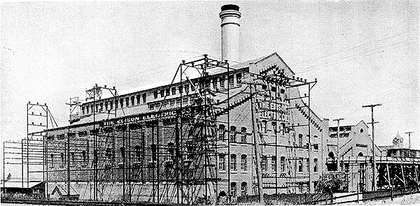
| Fig. 38. - Los Angeles No. 3 Receiving Station, Showing 60,000-Volt, 30,000-Volt and 15,000-Volt Circuits. |
The switching station buildings are constructed of concrete in the most substantial manner. The circuits are isolated from each other by means of concrete barriers and floors. Individual leads of the same circuit are, however, run in the same compartment. In spite of the large number of crossings called for by the wiring diagram, the dimensions of the building are not excessive. The Castaic sub-station is 66 ft. long and 41 ft. 6 ins. wide, with a cross-partition wall forming the switch-room. 40 ft. wide, and the transformer room 26 ft. wide. Provision has been made to connect horn lightning arresters to the circuits at these sub-stations, if it is found necessary after the line has been operated for some time.
The two transformer sub-stations have in their switching houses an arrangement identical with that in the other stations, except that openings were made in the west wall, through which leads were taken into the adjacent transformer house. The two were built together under the same roof and with continuous sidewalls so that there is on the exterior little to indicate the difference between the two ends of the station. In the transformer house provision has been made for two banks of 2100-kw transformers from the transmission line at 60,000 volts and delivering to the distribution at 30,000. The high-tension leads are tapped from two of the out-going 60,000-volt circuits in the switching house, and after passing through oil switches join in a common bus from which the transformers can be separated by means of knife-blade switches.
This switching, with the exception of the transformer switches, is on a concrete deck forming a complete second story in the switching house, 18 ft. above the floor. On the under side of this floor, there are also mounted the insulators for the 30,000-volt circuits. The 30,000-volt oil switches are, however, placed on top of the floor. The lightning arresters for the 60,000-volt circuits are on the wall between the transformer and the switch house, and are separated from each other by 6-ft. barriers, while the 30,000-volt arresters are against the end of the sub-station immediately below the oil switches and the outgoing 30,000-volt circuits.
At Castaic there will be installed at present one bank of transformers, 2100 kw, oil-filled and water-cooled. These transformers will supply power to a 30,000-volt, 40-mile transmission system now being built by the Ventura County Power Company, west from Castaic to Saticoy, where a branch is taken off to Oxnard, while the main line continues to Ventura. This branch will eventually be continued to Santa Barbara, 3o miles farther, where the Edison Electric Company has extensivev power and railway holdings.
At San Fernando there will be installed a 1200-kw bank, which will supply power at 2300 volts to lamps and motors.
LOS ANGELES RECEIVING STATION.
The Kern River No. I transmission line terminates in Los Angeles, 117 miles from the power plant, at the steam and transformer station known as Los Angeles No. 3. This station, which was partially described in the ELECTRICAL WORLD AND ENGINEER of March 11, 1905, is constructed to receive, transform and distribute to the local sub-stations power transmitted from the company's water-power plants on Santa Ana River, Mill Creek, Lytle Creek and Kern River, and also contains a large steam auxiliary plant to supplement the water-generated power. It receives power at 60,000 and 30,000 volts and generates and distributes at 16,000 and 2300 volts.
Both of the Kern River circuits enter the station through the east gable, as shown in Fig. 4o. After passing through choke coils the lines enter oil switches which connect them to their respective bus-bars. There is also an oil tie switch between the two buses. Each transformer has an oil switch which can be connected by means of a double-throw knife-blade switch to the bus-bars belonging to the west or to the middle circuit. When the east circuit comes in it will have a pair of oil switches so that it can be run on either of the bus-bars.
 |
| Fig. 39. - Plan of Los Angeles No. 3 Receiving Station. |
There are four step-down 4500-kw transformer banks, with their secondaries wound for either 16,000 or 32,000 volts. Under ordinary conditions, all energy received from Kern River will be handled through the double 15,000-volt bus. The transformers are cooled by forced-oil circulation. The oil, after leaving the transformer, is handled in the same manner as at Kern River. It enters a receiver, is forced by variable-speed centrifugal pumps into boiler-tube cooling coils outside the building and passes back into the pressure line which fills the transformers. There being no extensive supply of cold water available, the cooling water is circulated continuously from the oil cooler basin into elevated troughs from which it drops over a series of screens, where it is cooled immediately before falling on the section containing the hot oil.
This building also contains provision for switching the old 30,000-volt, 8o-mile transmission line, fed by the Santa Ana and Mill Creek plants, with its various branches and all the 15,000-volt distribution around Los Angeles. The arrangement of the various circuit bus-bars, oil switches and the transformers is shown in the accompanying diagrams. All switches and circuits are controlled from a 12-panel switchboard on the gallery of the turbine room, which is equipped with the necessary control switches and instruments for the 6o,000, 30,000, 15,000 and 2300-volt buses.
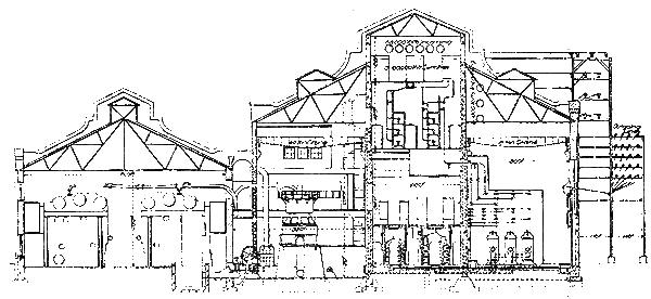 |
| Fig. 40. - Vertical Section of Los Angeles No. 3 Receiving Station. |
All bus-bar wiring connections to the transformers and the outgoing circuits are carried in ducts. In the new portion of the station these are filled with 15,000-volt leaded paper cables of 211,000 cm cross-section, with the exception of those for the Westinghouse turbo-generator, which has 400,000 cm cables.
There were installed in the steam end of this plant during 1903 two 2000-kw, 2300-volt Curtis turbo-alternators, with 4000 horse-power of Stirling boilers, in 500-hp units. When it became necessary to order an extension for the plant, in 1905, larger size apparatus was determined upon throughout. An additional 5250 horse-power in 750-hp units was installed in the boiler room.
The turbine installation in the new plant consists of a single 6000-kw Westinghouse-Parsons turbo-alternator, with Worthington condensing equipment. The steam end is of the Westinghouse standard construction, receiving steam through an intermittent valve. This steam, before reaching the machine, passes through a separator, an automatic butterfly valve, and a hand-operated throttle valve. This unit is four-stage, single-flow, and is operated at from 27 1/2-in. to 28-in. vacuum. Thus far loads up to 10,000 kilowatts have been carried on the machine without any indication of its maximum load being approached. The by-pass throttle does not open until a load of 9000 kilowatts is reached under normal steam and vacuum conditions.
| |||
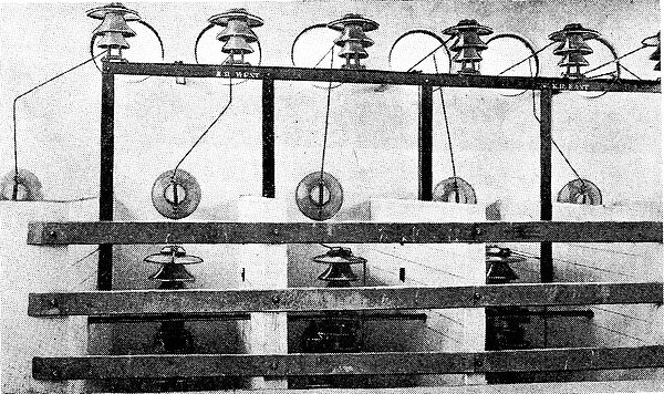
| Fig. 41. - High-Tension Lines Entering Los Angeles No. 3 Receiving Station. |
The generator is wound for 16,500 volts, star connected, and is run with grounded neutral on the 50-cycle distribution of the company. The generator operates perfectly and runs in multiple with the main system without causing any disturbance whatever. Between the neutral of the machine and the station ground wire, a potential difference of several hundred volts exists under operating conditions, with the machine in connection with star-to-delta-connected transformer banks. This voltage and the resultant flow where the neutral switches close vary with the number of transformers and the load on them, but does not appear to vary from other causes. An observation of the wave shape across the neutral connection showed a somewhat peaked potential wave at three times the frequency of the main circuit. For the present the exchange current is limited by the insertion of the choke coil in the neutral connection. At a later date a resistance will be substituted for the coil. This phenomenon in one shape or another is observable on all Y-connected four-wire generator installations.
Steam from the exhaust end of the turbine passes to the atmosphere during warming up through an automatic release valve. After the machine is up to speed, 750 r. p. m., the steam is condensed into a 24,000-sq. ft. condenser, and the water of condensation returned to the hot-well by a two-stage motor-driven centrifugal pump. The vacuum space is cleared of entrained air by means of a steam-driven dry-vacuum pump. Forty-nine cu. ft. of condensing water are forced per second through the condenser by means of a 3o-in. Volute centrifugal pump, direct-connected to a 450-hp induction motor, receiving power from the 2300-volt station mains.
| |||
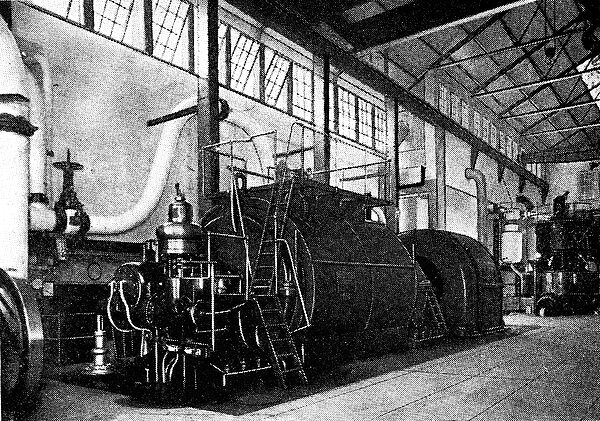
| Fig. 42. - Interior of Turbine Room of Los Angeles No. 3 Station. |
A transformer bank stepping from 15,000 to 2200 volts is to be connected to the machine leads so that the auxiliaries can be transferred to the generator leads after the unit is in full operation.
Circulating water leaving the condenser passes beneath the boiler room in a steel-lined, concrete duct to the edge of the Edison Electric Company owns in entirety, the company has . a two-thirds interest in five excellent power sites on the Kings River where 95,000 kw can be developed.
CONCLUSION.
As mentioned in the articles appearing in the ELECTRICAL WORLD AND ENGINEER two years ago, the earlier water-power plants of the Edison Electric Company consist, in the order of their construction, of Mill Creek No. 1 (original Redlands) ; Santa Ana No. 1, Mill Creek No. 2, Mill Creek No. 3, Santa Ana No. 2, and Lytle Creek. These plants, which have a total output of 8700 kw are located in San Bernardino county, and in addition to supplying local power demands in the vicinity transmit power at 30,000 volts by means of an 80-mile transmission line to Los Angeles.
In addition to the water-power plants the company has a steam generating rating of 14,075 kw. It is expected that the Kern River plant will be able to deliver in Los Angeles a Maximum of 23,000 kw. This with the other water-power plants will give a normal hydro-electric generating rating of about 30,000 kw delivered in Los Angeles. Thus far the company's maximum peak load has been about 20,000 kw. However this by no means indicates the demand made on the company for power, and it is the company's expectations, judging by past experience, that all of its power will be contracted for as fast as it is available. The Edison Company is the only power corporation in Southern California that aims to keep ahead of the demand for power by the construction of new plants, and this policy has proved an excellent one as compared with some of the other power interests who have at times been badly crippled by an insufficient supply, and have had to call on the Edison Company for power.
The cities in Southern California supplied with electric power for lamps and motors by the Edison Electric Company comprise a population of 418,500 and include Los Angeles, Pasadena, Pomona, Santa Ana, Redlands, Santa Barbara, Santa Monica, Ocean Park, Venice, Long Beach, Monrovia, Whittier, Riverside, Colton, San Pedro and Redondo. The transmission lines traverse Los Angeles, Orange, Riverside, San Bernardino, Kern and Ventura Counties.
Gas plants are operated in each of the cities named with the exception of Los Angeles, Pasadena and Redondo, the Santa Monica plant supplying Ocean Park and Venice. The gas plants have a generating capacity on a 12-hour run of 1,798,000 cu. ft. and double that for 24 hours. A storage capacity of 590,000 cu. ft. is provided. Crude oil is used for fuel.
As indicative of the conservative and efficient management of the properties under the company's control, it is interesting to note that in the four years, 1903 to 1906 inclusive, the proportion of operating expenses to gross earnings has been reduced from 52 per cent to 41 per cent. The following table covering the field of activities of the company as of record on January 1, of each of the years. 1905, 1906 and 1907, shows the excellent growth made during those years, and also incidentally illustrates the effectiveness of the selling and publicity campaigns carried out by the company.
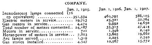 |
Several interesting conclusions can be drawn from a study of these figures. For example, in the two years, 1905 and 1906, the company's incandescent lamp service increased 67 per cent with an increase of 66 per cent in the number of meters. Gas meters increased 227 per cent, and a corresponding increase of 247 per cent in the number of gas stoves installed indicates a remarkably efficient sales staff in the gas department. The figures also indicate that there is practically no gas illumination in the territory served by the Edison Company. The number of electric motors installed increased 197 per cent with an increase of 152 per cent in their horse-power. The average horse-power per motor decreased from 10.82 to 9.18, indicating an increasing use of small motors, presumably in small manufacturing lines.
The Edison Electric Company is incorporated under the laws of Wyoming and has issued $11,200,000 of its capital stock, consisting of $4,000,000 preferred and $7,200,000 common. The company has outstanding $50,895,000 in bonds and debentures.
The following-named gentlemen are officers of the company President, John B. Miller, Pasadena ; vice-presidents, Henry Fisher, Redlands; Wm. R. Staats, Los Angeles ; H. H. Sinclair, Pasadena ; John W. Edminson, Los Angeles; secretary, R. H. Ballard, Los Angeles ; treasurer, W. L. Percey, Pasadena ; general manager, A. L. Selig, Los Angeles.
The construction of the Kern River No. 1 power plant was prosecuted under the general supervision of H. H. Sinclair, vice-president of the company, who originally located the power sites on the Kern River and on most of the other streams whose power supplies are controlled by the Edison Company. The hydraulic features of the Kern River work, including the dam, gravity tunnels, pressure tunnel and many of the details of the water-wheel equipment were designed under the supervision of F. C. Finkle, chief hydraulic engineer, and now consulting engineer for the company. F. ,E. Miller, as superintendent of power development had charge of and, at times, direct supervision over, the construction work. The electrical details were looked after by Ralph Bennett and R. J. C. Wood. G. E. Decker represented the company in the installation of the machinery. John Taylor, formerly chief operator at the Santa Ana No. I plant, has been placed in charge of the operation of the Kern River No. I plant. To these gentlemen the writer is indebted for many courtesies and for the furnishing of the drawings and much of the data which have made these articles possible.
