[Trade Journal]
Publication: Electrical World
New York, NY, United States
vol. 55, no. 12, p. 741-746, col. 1-2
DISTRIBUTION SYSTEM OF THE SOUTHERN POWER COMPANY.
A Summary of Generating Stations, Substations and
Transmission Lines, with a Description of
Recent 100,000-Volt Work.
By J. W. Fraser.
IN the spring of 1904 a 10,000-hp hydroelectric plant was completed at India Hook Shoals, near Rock Hill, S. C., by the Catawba Power Company, the market in view being the cotton mills in nearby towns. During construction very little encouragement was received by those who may be considered the pioneers in the distribution of hydroelectric energy to cotton mills. Electricity had almost to be given away to the first mill companies that installed motors, but by the spring of 1905 the demand for electric service was so great that those interested in the Catawba Power Company formed a larger organization, known as the Southern Power Company, with the intention of distributing energy to all the mills within economical transmitting distance of certain water-powers on the Catawba and Broad Rivers which could be developed at a reasonable cost. As a result there are now in commission the following additional stations:
Great Falls, 32,000 hp; Rocky Creek, 32,000 hp; Ninety-Nine Islands, 24,000 hp, supplying power to 140 odd mills, and integrating a load of over 100,000 hp for 10 hours.
| |||
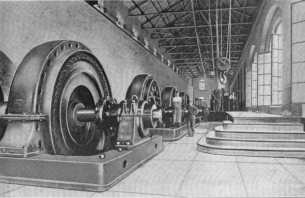
| Fig. 1 -- Interior View of Great Falls Generating Station. |
| |||
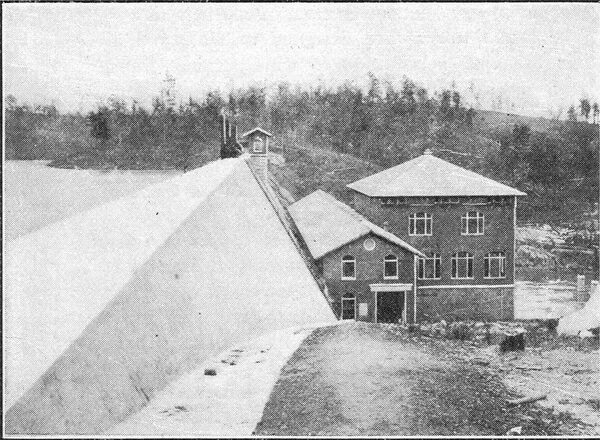
| Fig. 2 -- Exterior View of Great Falls Generating Staton. |
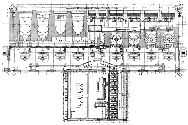 |
| Fig. 3 -- Plan of Great Falls Generating Station. |
It is notable that when the Catawba plant was designed, 13,000 volts was considered the limit in voltage, and that when the Great Falls plant was designed (autumn of 1905) some of the most prominent engineers in the country thought it would be wiser to use 33,000 rather than 50,000 volts. In less than four years from the time the Great Falls plant was designed and when more towns could not be reached economically at 50,000 volts, the transmission of energy at 100,000 volts was considered entirely feasible.
Work on Great Falls Station was commenced in the summer of 1905 and completed in the spring of 1907. Rocky Creek Station was commenced immediately after the completion of the Great Falls plant and finished in the spring of 1909. Active work on the Ninety-Nine Island station was commenced early in 1909 and this plant is now being put in service. Work on the 100,000-volt lines and substations now in commission was commenced in December, 1908. and was completed in December, 1909.
As the 50,000-volt lines were described in the Electrical World, May 25, 1907, they may be passed over and a few details concerning the recently installed 100,000-volt lines given.
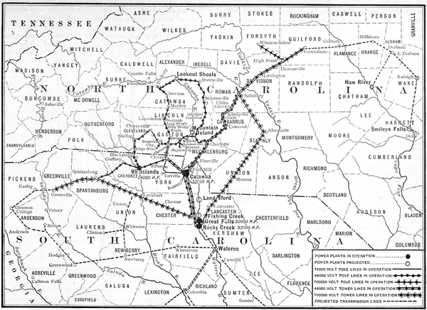 |
| Fig. 4 -- Map of Transmission Lines. |
| |||
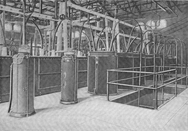
| Fig. 5 --High-Tension Switch Room, Great Falls Generating Station. |
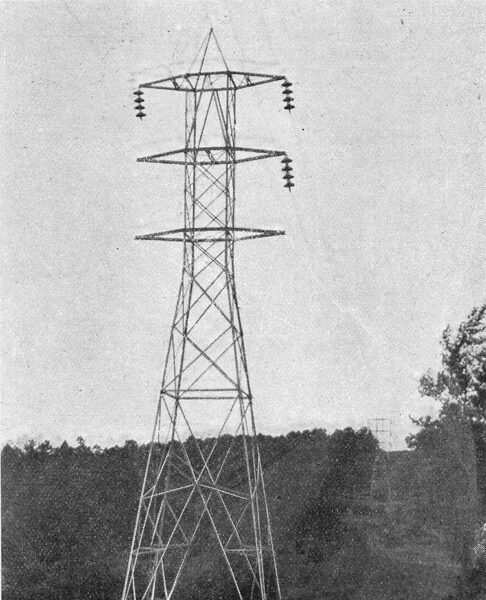
TOWER DATA.
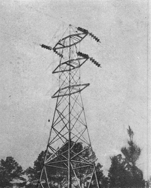
The 100,000-volt towers have been designed to carry two circuits of No. 2-0 (7-strand). The height to the lowest conductor is 40 ft. (44 ft. to cross-arm); height to the second conductor is 48 ft. 4 in.; height to the third conductor is 56 ft. 8 in.; height to the ground wire is 65 ft. Horizontal distance between conductors, 15 ft. Tower width at ground line, 15 ft. 6 in.
The suspension towers are designed to withstand two conductors breaking, with a normal wind strain of 15 lb. per projected square foot of conductor, and 30 lb. per square foot tower area, in 600-ft. span.
The strain towers are designed to withstand all wires breaking in addition to wind strain. Strain towers are used as every tenth tower on tangents. Angles of less than 15 deg. are made on one-strain tower, while angles greater than 15 deg. are made on two or more strain towers. Extra heavy towers (25,000 lb. in either direction) are used on spans of over 1000 ft., and for large angles.
The maximum allowable stress on copper at o deg. Fahr. is 17,000 lb. (no ice) ; longest span is 1400 ft.
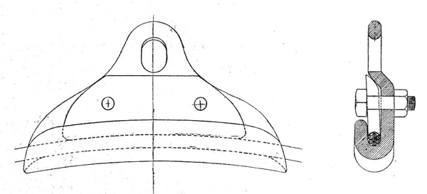
The anchors for suspension towers are 6 ft. in the ground, and those for strain towers, 8 ft. in the ground. The foot is made of 12-in. channel irons 30 in. long. No concrete is used except on large angles and in soft soil. In tests, 6-ft. anchors in sandy soil pulled out at 24,000 lb., while 8-ft. anchors in sandy soil did not pull out at 30,000 lb. The ground wire is f^-in. Siemens-Martin steel, stranded.
| |||
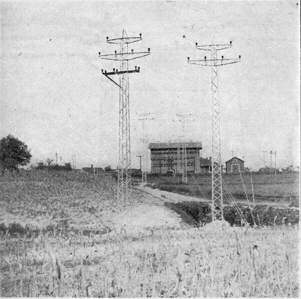
| Fig. 6 -- 50,000-Volt City Line. |
| |||
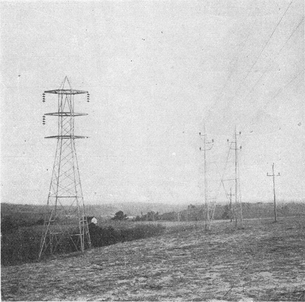
| Fig. 7 -- 100,000-Volt Strain Tower. |
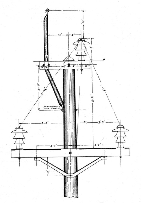 |
| Fig. 8 -- Detail of Pole Top for 50,000-Volt Single-Circuit Transmission Line. |
| |||
| Fig. 9 -- 100,000-Volt Transmission Tower. |
The insulators have a diameter of 14 in. for the outer shell and 7 in. for the inner shell. Hooks and eyes were selected for connecting insulators together merely because of simplicity. Hooks were readily made to stand over 10,000 lb. in tension. The mechanical test on insulators was 8000 lb. tension. In some cases these tests have run over 12,000 lb. The number of insulators used on suspension towers is four, and five on strain towers. On one line a single lo-in. disk is being installed; six of these are used on suspension, and seven on strain towers.
Star transformer connections are used at generating and tie-in transformer stations, and delta connections at substations. The generating transformers are grounded through 112 ohms, metal resistance. Oil switches are used on all transformers. Disconnecting switches, as shown in the accompanying illustrations, are for temporary use only.
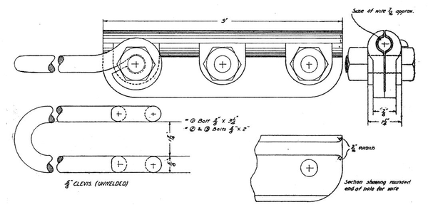
As no suspension clamp that seemed satisfactory was on the market the one shown in Fig. 18 was designed. The upper part of this clamp has a hole sufficiently large to swing free on the insulator. The lower part has a groove, the bottom of which is shaped to fit the slope of the conductor. After the conductor is adjusted so that the insulator hangs vertically, the clamping piece is dropped in over the conductor and the two bolts pulled up. This makes a wedging action, which clamps the conductor as tightly as desired.
The groove and wedge is so shaped at the ends that if the conductor should break in any span the clamps would not kink the wire. The terminal clamps, which were also of home make, are very similar to a large three-bolt guy clamp with only one groove and a clevis at one end to slip over the hood on the insulators. Both clamps proved entirely satisfactory.
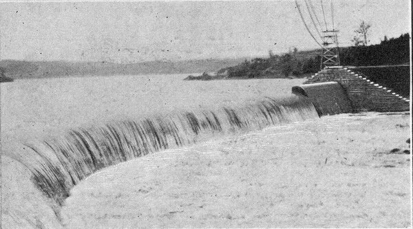
| |||
| Fig. 10 -- Catawba Dam. |
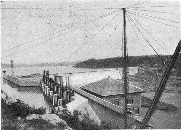
| |||
| Fig. 11 -- Rocky Creek Generating Station. |
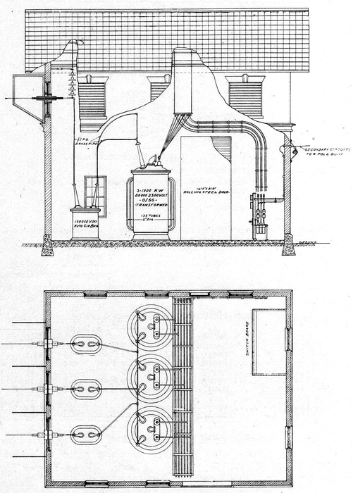 |
| Fig. 12 -- Elevation and Plan of Standard 3000-Kw. 100,000-Volt Substation. |
| |||
| Fig. 14 -- 100,000-Volt and 50,000-Volt Transmission Lines. |
| |||
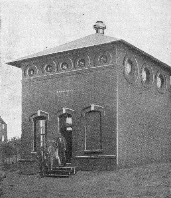
| Fig. 15 -- Standard 50,000-Volt, 3000-Kw Substation. |
The suspension insulator brings in one problem which, although it causes considerable trouble in locating towers over a rough country, many ultimately prove of decided advantage. It a tower is so placed that the conductor when pulled to its proper sag does not hang as low as the clamps in the coldest weather, the location of the tower will have to be changed as the conductor cannot be tied down, as has often been done on pin insulators. This necessitates more accurate calculation of sag when one tower is considerably higher than the one next to it, and, when towers of one height only are used, often necessitates long spans. Moreover, when many towers are on one steep incline, it is difficult to distribute the stresses on them all, the tendency being for the highest tower to take more than its proportion of the load. One great advantage is evident, namely, that unless the wires break, the suspension tower takes only wind strain, and consequently may be made tolerably light and cheap, providing a heavy tower is used where there is any chance of heavy strains coming on the line.
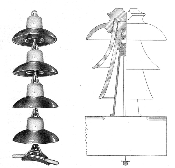 |
| Fig. 16 -- 100,000-Volt Suspension Insulator, Showing Clamp and Shield on Aluminum Wire. Fig. 17 -- Standard 50,000-Volt Insulator and Pin. |
 |
| Fig. 18 -- Diagram of 100,000-Volt Suspension Clamp. |
When the towers were being designed a little uneasiness was felt as to what would actually happen if one line broke. However, during construction, tests made by cutting fines showed that no trouble need be feared by two conductors breaking on a six-wire tower, providing the cross-arms are designed to withstand this strain and the body of the suspension tower is designed to withstand wind strain. A very tall tree was recently cut across the line with no further damage than the breaking of one conductor.
OPERATION.
The first section of 100,000-volt line, 143 miles in length, was put in operation Oct. 24, 1909, and the remaining portion cut in as quickly as completed. The insulation of the line, transformers and switches proved entirely satisfactory. Out of 47 transformers, only one bushing proved defective, and on investigation it was found that this one had been damaged in shipment. None of the bushings on the 20 oil circuit-breakers broke down. Up to the present time there have been only one sleet storm and two lightning storms.
From its experience, the company is led to believe that less trouble will be experienced at 100,000 volts than at 50,000 volts, and that the suspension insulator has decided advantage over the pin insulator for high voltages. The highest e.m.f. that has yet been put on the line is 125,000 volts. It may be of interest to some to know that the charging current per phase on the 143 miles of this line at 90,000 volts measured 40 amp (about 6200 kva), and that the voltage of the unloaded generators increased from 1300 to 1800 when this line was thrown on.
Following is a list of the apparatus installed at the various generating stations:
Catawba Station:
8 54-in. horizontal twin turbines, with quarter-turn for flood water.
4 650-kw., 60-cycle, 300-r.p.ni., 13,000-volt generators.
4 750-kw., 60-cycle, 300-r.p.m., 13,000-volt generators.
Great Falls Plant:
8 5200-hp horizontal twin turbines (72-ft. head.)
4 Type N, Lombard governors.
1 Type P, Lombard governors.
8 3000-kw, three-phase. 60-cycle, 225-r.p.m., 2500-volt generators.
2 400-kw, 450-r.p.m., direct-current exciters.
2 600-hp horizontal twin turbines.
8 1200-amp., 3000-volt, non-automatic oil circuit-breakers.
4 2000-amp., three-pole, 3000-volt automatic oil circuit-breakers.
12 2000-kw., o.i.w.c., 2400/50,000-volt transformers.
12 l00-amp., o.i.s. c. choke coils.
8 Three-pole, 200-amp., 60,000-volt oil circuit-breaker time-limit overload relays.
9 50,000-volt electrolytic lightning arresters, disconnecting switches, etc.
Rocky Creek station is practically a duplicate of Great Falls station. Ninety-Nine Islands station is practically a duplicate of Great Falls station, but only three-fourths its capacity.
 |
| Fig. 19 Diagram and Details of Anchor Clamp. |
 |
[Articles descriptive of various parts of the Southern Power Companys system have appeared in these pages as follows: India Hook Shoals plant. May 14, 1904. Water-Power Electrical Developments in the Carolinas, Nov. 10. 1906. Preliminary article on Great Falls station with data on transmission lines. May 25, 1907. Great Falls station, Dec. 28, 1907.]
