[Trade Journal]
Publication: Electrical World
New York, NY, United States
vol. 56, no. 19, p. 1134, col. 1-2
SUSPENSION-TYPE HIGH-VOLTAGE INSULATORS.
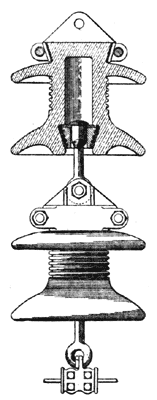
Two patents relating to transmission-line insulators of the suspension type were issued on Nov. 1. In a patent granted to Mr. R. M. Johnston, of Mansfield, Ohio, a description is given of a form designed so as to provide a maximum dielectric separation between points of opposite potential and to obtain interchangeability of insulator sections. Means are also provided for permitting the sections to align themselves properly with respect to each other. In the form shown in Fig. 1 the hollow body portion of the insulator is integral with the protecting skirts. The upper part is held within clamps compressed against cement held on the conical part of the body. The lower part contains an enlarged cavity within which rests the head of a swivel bolt provided with an eye at its lower end. The inventor calls attention to the fact that there is no conducting material within the interior of the insulating section, the construction being such as to reduce to a minimum the electrostatic stresses and the liability to puncture by lightning and abnormal voltages, while the shape and relative position of the upper and lower protecting skirts in combination with the long body of the insulating material prevents the formation of "still-air spaces."
 |
| Fig. 1 — Johnston Insulator. |
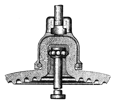
An insulator arrangement patented by Mr. J. E. Noeggerath, of Schenectady, N. Y., is shown in Fig. 2. In this insulator special means are provided for resisting the mechanical stresses to which the insulator is subjected in service. The insulating disk is formed of porcelain, the upper knob of which is supported by a cast-iron bell to which it is anchored by means of a wire inserted through a tangential hole cut in the rim of the bell and forced around in the space formed by grooves cut within the bell and along the edge of the insulator knob. Within the knob is a central cavity enlarged at its inner end to form a circular inclined ledge against which is supported a strain bolt by means of copper balls, which when forced into contact with the porcelain will compress somewhat and distribute the pressure instead of crushing the porcelain. In order to exclude moisture the unoccupied spaces between the several parts of the unit are filled with cement which will yield properly to tensile stresses.
 |
| Fig. 2 — Noeggerath Insulator. |
