[Trade Journal]
Publication: The Electrician
London, England
p. 831-834, col. 1-2
THE HYDRO-ELECTRIC POWER SCHEME OF THE
CITY OF WINNIPEG.
INTRODUCTION.
In such a progressive Canadian city as Winnipeg is known to be it would have been surprising to find that electrical energy was being otherwise than largely used for all purposes. As a matter of fact, the development in this direction is very satisfactory, a condition of things which is doubtless aided by the large amount of water-power which is available- in the vicinity. In what follows we give a description of the hydroelectric scheme that has been designed and set to work for supplying the city of Winnipeg, our information being largely based on a Paper recently read by Mr. A. Chase before the Canadian Society of Engineers. Briefly, the undertaking as now completed consists of a 30,000 H.P. hydro-electric plant operating under a 45 ft. head (this is to be enlarged to 60,000 H.P.); a 77-mile 60-cycle 72,000-volt transmission system, consisting of one double-circuit steel tower line with concrete foundations; a terminal station in the city, at which the transmission line pressure is reduced to 12,000 volts; an underground 12,000-volt distribution to sub-stations; and two sub-stations where the voltage is reduced to 2,200-volts alternating current and 550 volts direct current.
 |
| Fig. 1. |
GENERAL DETAILS OF SCHEME.
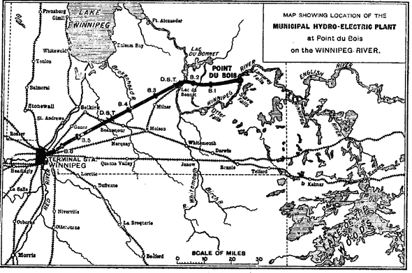
The power station is built on the Winnipeg river, which flows through the eastern portion of the Province of Manitoba and empties into Lake Winnipeg. Its chief gathering grounds are in the lake country of Western Ontario. The Winnipeg River, with its tributary the English River, also drains a portion of Northern Minnesota, North-western Ontario and Eastern Manitoba, forming in all a watershed of 52,000 sq. miles, of which the English River drains 21,000 sq. miles. This watershed is nearly all Laurentian in character, and has a considerable proportion of forested area untouched by the lumberman. Many small lakes are found in all the districts, the river proper passing through several, of which the largest is Lake of the Woods. The gross lake area is 5,650 sq. miles, that of the Lake of the Woods is 1,200 sq. miles (see Fig. 1).
This area has an average annual precipitation of from 18 in. to 25 in. For instance, at Winnipeg, for the years 1907, 1908, 1909 and 1910, the precipitation was 22.7, 21.8, 25.2 and 19 in. respectively. The average yearly run-off of the watershed above Keonra (an area of 27,000 sq. miles) is given by W. Thibaudeau, in a report dated March 24, 1908, as about 22,000 ft. per second, the range of average yearly run-off for the entire river being also given as from 29,000 ft. to 39,000 ft. per second, as determined from the precipitation records of the years from 1896 to 1907. From the water-flow gaugings taken by Mr. D. A. Ross and readings of water elevations at Point du Bois, the average discharge at Otter Falls, for a drainage area of 49,000 sq. miles, has been estimated at 30,000, 32,700, 23,000 and 29,200 ft. per second for the years 1907, 1908, 1909 and 1910 respectively. This corresponds to an average proportion of run-off to precipitation' for the four years of 37 per cent., if the somewhat doubtful assumption is made that the precipitation at Winnipeg is representative of that of the Winnipeg River drainage area, which is considerably to the east of the city. From the records of water elevations at Point du Bois, the minimum flow for the period covered is estimated at 16,000 ft. per second, and the maximum at 55,000 ft. per second.
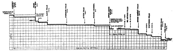
The numerous lakes and swamps in this region have naturally a strong influence in making the discharge of the river uniform. The records from daily observations and from the water marks: on the shores of the elevation of water surfaces at Point du Bois indicate a minimum discharge of about 16,000 cubic ft. per second and a maximum of 90,000 to 100,000 cubic ft. per second. This latter is taken from old flood marks. It may be safely said that the Winnipeg River has a more uniform flow than any other undeveloped river in America, or perhaps in the world, and it offers, besides, many natural sites for the development of large reservoirs for the farther improvement, of its character of flow. Fig. 3 shows a profile of the river from the mouth of Rainy River to Lake Winnipeg. It will be noted that, as in all Laurentian rivers, the individual falls are not great. The entire tall in this distance is 347 It., or about 2 It. per mile.
The engineers of the city of Winnipeg, reporting in 1905 on three sites, chose that at Point du Bois as the most desirable then available for a hydro-electric station. The natural drop was from 33 ft. to 28 ft., depending upon the state of the river, and the dams as now constructed have the effect of increasing the fall to 47 ft. and 43 ft. at low and high-water respectively. There was originally a stretch of smooth water, 8 miles long and about 3,600 acres in extent, above Thirty Foot and below Lamprey Falls. This acreage has now been increased artificially to nearly 6,000 acres, with very considerable advantage to the operation of the city's power plant. Just how great a value this huge catchment area at the power house has may be seen by a glance at the table below, which shows the results of drawing thereupon, assuming that the entire energy of the average minimum flow of the stream is converted into electricity--i.e., into the equivalent of 65,000 H.P. for 24 hours.
Daily load factor. Peak load.
Per cent. H.P.
20 ......... 325,000
40 ......... 162,000
60 ......... 108,000
80 ......... 81,000
100 ........ 65,000
It is a most fortunate city which has an average load equal to 60 per cent. of its peak, and so high an average can only result from very varied classes of service and from high-class management. It is thus seen that, with a catchment area capable of delivering at the generator terminals 12,500 H.P. for 24 hours per 1 ft. of surface, it would be quite reasonable to equip the city's generating station with machinery of 100,000 H.P. overload capacity. It is not possible without a definite load curve to determine to what extent the catchment area would be drawn upon for various load factors, even if full overload were assumed as the peak for the day. The capacity for which the city's development is designed is 60,000 H.P. on the rated dimensions of the machinery, an output well within reason for the site and conditions.
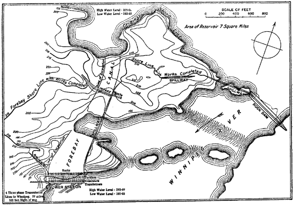 |
| Fig. 2.--Plan Showing Location of Power Station. |
HYDRAULIC WORK.
Fig. 2 is a general view of the works, and gives a very fair idea of the natural surfaces at Point du Bois before the beginning of the building operations. The stream falls over two rock ridges at different elevations, the greater portion of the drop occurring at the lower ridge. The problem of concentrating the entire increased head at the power house site chosen was a simple one, involving chiefly the excavation of a canal across the west shore ends of the ridges and the construction of a retaining wall along the east side of the canal so formed.
To increase the natural fall, river walls and a dam were necessary, and the elevations of these were so chosen as at once to ensure the desired head of water and the discharge of flood waters without over-topping certain fixed elevations. The crest of the principal weirs is 7.4 ft. below this fixed elevation, and there is a gross length of 1,500 ft. of weir made up in four sections: 550 ft. on the original high-water course at the crest of the falls, 480 ft. on the earth-covered point of the land forming part of the upper ridge, 245 ft. on the canal wall immediately above the intake or control gates, and 225 ft. on the same wall inside the gates. Certain portions of the canal wall are respectively 3 ft. and 2 ft. lower than the "dry" elevation, besides which two weirs for the disposal of waste are located one at each side of the canal at the power house, and a waste sluice is placed in the forebay wall immediately above the control gates. The south end of the canal is occupied by the power-house structure, from the west end of which a wing dam extends to high ground.
River wall No. 1 occupies the portion of the crest of the falls which was formerly covered with water only at the flood stages of the river. River wall No. 2, which is upon what was originally dry land, was built of concrete, owing to the fact that for a considerable portion of the ridge the rock is of low elevation, and the possibility of the earth being washed away would make probable the loss of considerable head by the lowering of the water level. The crest is at the standard over-fall elevation--i.e., at minimum head-water level. The portion of the forebay wall inside the canal is provided with a crest at this elevation to ensure a surface cleaning current within the canal and a constant inflow through the control gates.
Considerable trouble has been experienced in these northern climates owing to the loss of heat through the walls of the canal at the ends of the power house. This is the case to such an extent that the head gates in the first and last inlets may be quite frozen up. To prevent this contingency if possible, the section of the forebay walls next to the power house has been increased, and a series of air chambers has been provided in-them. These chambers are inter-connected, and the temperature of the air in them is not likely to fall below 32°F. These air chambers are also extended up the canal past the overflow sluices to prevent the closing up of the sluices by the formation of ice thereupon, a not uncommon occurrence.
Careful study has been made of the velocity of the water at the critical points in its passage through the works. Fortunately, above the intake, the river is very broad, and the mouth of the bay at the head of the canal is so wide that the water will approach the canal slowly, accelerating as it nears the control inlets. Through these inlets, and under full load conditions--60,000 H.P. at the generatorsit will be moving at 6.4 ft. per second, but will emerge into a gradually widening passage until at the greatest section of the canal forebay it is moving very slowly. Thence its speed increases to 1.5 ft. per second through the outer piers of the rack room of the power house to 1.7 ft. per second through the inclined steel racks, to 2.8 ft. per second through the wheel pit inlets, to 20 ft. per second in the turbine runners, to 8 ft. per second in the neck of the draft tube, and decreases again to 3.3 ft. per second at the exit or seal of the draft tube.
Along the northern face of the building, where the natural rock surface slopes sharply southward, a huge apron has been. built consisting of an 18 in. sheet of reinforced concrete. This upward sloping apron causes a gradual decrease in the cross-section of the path of the water. It also, incidentally, forms a gravity dam, and is securely tied to the series of wheel pits to the south of it. The rack structure sits upon this apron.
 |
| Fig. 3.--Partial Profile of Winnipeg River. |
The rack bars are 45 ft. long on the and their supporting structure is designed in 7 ft. bays, at whose junctions placed the trusses, each consisting of a main rafter and three struts to a common foot plate. By this means the minimum of metal section is exposed to the currents of entering water. The importance of low rack velocities in the satisfactory operation of a hydraulic plant can hardly be over-estimated, as, besides diminishing the certain loss of head, this characteristic minimises the tendency of debris to accumulate and choke the racks. The inlets to the wheel pits are liberal, each being 16 ft. by 20 ft. clear, with rounded piers between them, and each with a rounded entrance into the turbine chamber. The draft tube is a 10 ft. by 15 ft. oval pipe at its inter-section with the turbine pit floor, and expands to 13 ft. by 23 ft. at such a rate as to make the velocity curve smooth throughout its length.
| |||
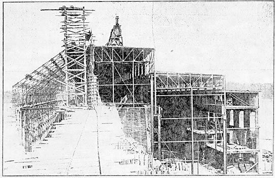
| Fig. 4.--West-End of Power House: Temporary Board-Wall Removed, May 12, 1911. |
POWER HOUSE BUILDING.
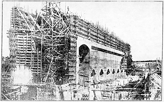
The quantities of water handled in this plant are unusually large, and the feature most noticeable as a result of this fact is the huge scale on which the power house is constructed. The building, for the accommodation of an equipment of a rated capacity of 32,000 is 250 ft. long, 150 ft. wide and 100 ft. high. Almost the entire construction is of concrete and steel. Timber is used only in the stop logs, in the sheathing of the rack structure, which is used as a gravity dam in the gap between the present power house and the wing dam, and in some weather curtains suspended from the outer walls of the rack room.
Figs. 4 and 5 show views of the power house while in course of construction.
| |||
| Fig. 5.--Power House, South-West, August 5, 1910. |
Four grades of concrete are used, plain and reinforced, each of 1:2:4 and of 1:3:5 aggregate respectively. The native rock, which was crushed to pass a 2-1/4 in. ring but not screened, was used in all the plain concrete construction. It was crushed to pass through a 1-1/4 in. ring and screened for the reinforced concrete. A sufficient supply of a superior grade sand was discovered about 2 miles from the site. Portland cement was used throughout. All weirs and river walls, the power-house foundations and most of the walls of the superstructure were built of plain concrete. The wheel pits and the floors of the apron, the wheel pits and the main building, as well as all the galleries and roofs, were made of reinforced concrete. The wheel pits were designed each as a self-supporting reinforced concrete tank, thus permitting the reinforcement to be so disposed as to take up definitely known tensions, beam action being avoided as far as possible. The reinforcing steel was bent round the inlet to the pit, and the large shaft opening into its south wall, or was run deeply and anchored into the adjacent concrete masses at the corners of the chambers. Except in the floors, galleries and roofs, the reinforcing steel used was in the form of twisted square steel bars with an elastic limit (after twisting) of 50,000 lb. per square inch. That used in the roofs, floors and plaster walls of the building was a special form of expanded metal. All beams were fireproofed with concrete, metal lath having been first wrapped about the bottom flanges.
Temperature and crystallisation effects in the concrete were compensated in two ways. The river walls were built in alternate sections of 50 ft., the ends of the completed sections being painted with two coats of heavy asphalt before the remaining sections were built. This system has generally been successful, but in certain shallow sections subsidiary cracks of small importance have been discovered where the gradient of the profile of the wall foundation suddenly changed. The powerhouse foundations, consisting, besides the series of draft tubes, of a series of flat tail race arches upon supporting walls tapered in plan, were built in pairs of arches; the two adjacent spans, which were built as a unit with a mid wall, rest upon asphalt painted skewbacks formed upon alternate tail race walls.
The contraction joints are thus 56 ft. apart. By this means the use of reinforcing steel in these arches was avoided, except in the most westerly arch, which is designed as a beam, one reaction of which is taken by the exciter tail race wail and the other by the extreme westerly tail race wall, and except in those portions of the four tail race arches which support the two lightning arrester bays of the building. In the other elevation of the building the foundations were separated into three portionsthe arrester bays, the transformer and generator room and the turbine and rack rooms; this was effected by the use of two vertical expansion joints running the entire length of the building. Above the tail race arches parting planes, asphalted and keyed with wooden strips, were provided in the main walls with considerable success in avoiding unsightly cracks, which are almost sure to appear in long concrete buildings unless great care is taken. All the walls under the apron, the shells of draft tubes where these project above the natural surface, and certain other sections of the work were provided with "contraction steel" to the extent of one-third of 1 per cent. of the section. A very considerable quantity of steel was used in providing for shear forces at unavoidable joints in the piers and walls.
(To be concluded.)
