[Trade Journal]
Publication: The Electrician
London, England
p. 870-874, col. 1-2
THE HYDRO-ELECTRIC POWER SCHEME OF THE
CITY OF WINNIPEG.
(Concluded from page 834.)
TURBINES AND ELECTRICAL PLANT.
The general arrangement of the power house is shown in Figs. 6 and 7, which also illustrate several unique features in the hydraulic construction made necessary by the high velocities that have to be controlled. The problem of choosing the most desirable type and dimension of generating unit also required much careful study. The great power capacity available, along with the large prospective market, indicated the use of as large a unit as possible. The moderate head, and consequently the large quantity of water which would have to be handled, set a definite limit upon the dimensions of the unit. The desire for a compact equipment predicated the employment of the highest permissible speed. The choice, therefore, fell on a two-runner turbine unit, with a capacity at the coupling of 5,200 H.P. This was coupled to a three-phase generator with a normal rating of 3,000 kw. This unit will pass, at a net head of 45 ft., 1,250 cubic ft. of water per second at maximum output, and will run at 164 revs. per min. This quantity of water can be disposed of without unreasonably high velocities in the inlet or tail races.
It is proposed to employ three of these generators as one operating unit, and the switching is arranged on this plan, though provision has been made for the isolation of any machine, or, to a limited extent, for the rearrangement of the groups. This will give the operating unit a capacity of 9,000 kw., and five of these will form the complete installation, in addition to one spare generating unit. The transformers are of the single-phase type, and have a capacity of 3,000 kw. each, so that the bank of three make a unit corresponding to that of the generating equipment. This gives a very desirable arrangement from the point of view of ensuring continuity, flexibility and simplicity.
Power is generated at 6,600 volts, the frequency being 60. Five generators are being installed at the present date. Two 250 kw. 125-volt exciters, direct driven by water turbines, are being provided with the original installation, though it is also proposed ultimately to install two motor-driven exciters of the same capacity. The regulation of voltage will be by means of Tirrill regulators, with line-drop compensators. Transformation will normally be at a ratio of 1 to 10, though taps are provided which will permit a range of line pressure at the generating station of from 53,000 to 72,000 volts.
The generation and transmission circuits are all handled from a control gallery opposite the exciter hay, and, by means of a set of meter pedestals and remote control bench boards, those for each operating unit are isolated from each other. The low-tension (6,600-volt) leads-and 'buses are all isolated by barriers on the main floor of the station, and the oil switches are also fixed in separate compartments, one compartment being provided for each 9,000 kw. The high-tension wiring is all arranged in the upper portion of the switching bay, and the oil switches, of which there are three per unit, are located on the gallery, those for each unit being in a separate compartment. This high-tension wiring is arranged so that there is a distance of 4 ft. between wires and a clearance of 2 ft. between each wire and earth.
 |
| Fig. 6. Plan Showing General Arrangement of Plant. |
The transformers are of the oil-immersed, water-cooled type, each being built into a separate concrete-walled compartment, the entrance to which from the power-house floor is guarded by an iron-clad door. The case of the transformer is of a special pattern of boiler-plate construction, and is set upon a cast-iron base. The water-cooling coils are of brass tubing. A complete system of tanks, pumps, dehydrator and piping is provided, similar to that described below as part of the equipment of the Winnipeg terminal station.
 |
| Fig. 7. Cross-Section Through Power House. |
Each outgoing wire passes through a separate concrete compartment, in which will be placed the lightning arrester. The compartments for one circuit occupy that length of the building which covers two tail-racesthat is, the exceedingly liberal space of 56 ft. But the arrangement is very convenient from a constructional point of view. An electrolytic arrester is provided, with its horn gaps and operating mechanism, inside each compartment. Upon the roof beside each wire anchorage a set of horn gap arresters will be placed. The lines enter these compartments of the building through special "hoods" of reinforced concrete suspended from the wall. These hoods are open below, but the inlet through the wall is protected by a special entrance insulator of the Locke type.
TRANSMISSION LINE.
The transmission line is built over a private right-of-way 100 ft. wide. It is 77 miles long, and traverses a varied country, the eastern section being typically Laurentianrock, muskeg and scattered areas of arable soilthe western section crossing a prairie and farming country, several miles of which are closely wooded. Two lines of double circuit towers and a separate telephone line are to occupy this right-of-way. A patrol road 12 ft. wide has been built next the telephone line, and a considerable stretch of this road has been corduroyed, the bottom being most uniform.
| |||
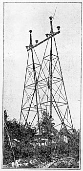
| Fig. 8. Standard Braced Tower. |
The telephone line consists of a single copper circuit of No. 12 B.W.G. copper, and is unearthed. It is carried on glass insulators which will stand a wet test of 19,000 volts. These occupy a single cross-arm upon a line of wooden poles, so placed that when the second line of transmission towers is equipped there will be a distance of about 30 ft. between the telephone wires and the nearest power conductor. The telephone circuit is transposed in a continuous spiral, four turns per mile. At every mile is an iron-clad plug box mounted upon a pole, at which the patrol man may call the line terminals; below each of these boxes is placed an insulated step, and the lineman will be furnished with a well-insulated plug and cord. Five telephone booths 'are also built at convenient points, generally between the transmission line switching towers. In. these are to be kept a stock of repair supplies for transmission line and telephone line use. A sleeping cot and a stove is also, provided in each of these booths, as well as a work-bench. The instrument used is a standard wall set with disconnecting switches for connecting to the telephone circuit, and for isolating each end of that circuit if necessary. At certain of the more isolated booths a stable will be provided.
| |||
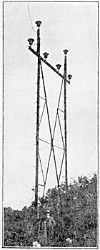
| Fig. 9. Standard Flexible Tower. |
The transmission system, which is being built for the output of the initial installation of generating equipment consists of a series of steel towers set upon concrete foundations and carrying two three-phase aluminum circuits, the wires of which arc spaced at 6 ft. centres. The capacity of each circuit is 11.250 kw. A second line of towers will be built a, soon a the increase in load makes this extension necessary. The tower foundations arc of two classes. The one for firm soil, which was intended to be a hollow concrete block set 7 ft. in the ground, but which, by the choice of the contractor, was built as a solid block; and the other for unfirm foundations, consisting of a reinforced hollow concrete block erected and grouted in place upon piling. In some instances, where the depth to firm bottom for piles was too great, a crib was used. On rock, the footing if shallow was anchored thereto.
The towers are of two general typesbraced and flexible. In the former group are the standard braced, transposition and angle towers, 50 ft., 50 ft. and 56 ft. respectively, and the special towers for river crossings; in all, nine types of these towers were used. Two types of flexible towers were used, one for firm soil and one for swamp construction. These towers are 42 ft. high. Figs. 8 and 9 show the standard braced and standard flexible towers respectively. The braced towers are spaced generally 1,200 ft. apart, this distance being varied, however, to suit the profile of the route or to fit the road crossed. The longest span on the line is 939 ft., and is at the Winnipeg River crossing. The flexible towers are placed intermediately, and serve as struts only. The first braced tower assembled was submitted to the following series of tests in May, 1909, at the shops of the manufacturers in Winnipeg. Across the line of the circuits 6,200 lb. was applied to one end of the cross-arm, which is 43 ft. above the ground. This represented a wind load of 1,040 lb. per pin, the tower being designed for 1,400 lb. per pin. Along the line a load of 7,200 lb. was applied, the equivalent of 1,200 lb. per pin. The moderate deflection in each direction indicated the satisfactory nature of the design. The flexible tower is designed to resist the same transverse line forces, but it can withstand only about 480 lb. gross at the cross-arm in the plane of the transmission line. The 2 ft. pin of standard wrought-iron pipe bearing the insulator is designed to be the weakest point in the wire supports, and this can withstand a pull of 900 lb. before there is any sign of failure, and under test it withstood 1,500 lb. just before breaking. On dead-end river crossing and railway crossing towers solid pins of the same diameter are used.
The conductors are of aluminum, and are made up of 19-strand cable of cross-section 278,600 circular mils. Each strand was tested before cabling, and a high ultimate strength and elastic limitnamely, 14,000 lb. to 15,000 lb. and 24,000 lb. to 29,000 lb. per square inchwere thus assured respectively. The cable was delivered on reels carrying not less than 4,000 ft., and the joints in stringing are made with 18 in. elliptical tubular sleeves, three complete twists being given. The test of a sample joint indicated that this joint is as strong as the cable itself. In stringing this cable great care was exercised to prevent contact thereof with the steel or with rocks; it was pulled over each tower as the reels were unwound, a stout pine cross-arm with wooden pins in place being secured upon the channel-iron cross-arm of the tower. The sags were carefully calculated and checked, and were formally approved by the cable manufacturers before the work was begun. A set of curves of sags for varying spans and temperatures was prepared, and a simple set of auxiliary curves was laid out for determining the proper adjustment of the standard sag for differences in the elevation of consecutive towers. Each span was sighted in separately as the tying-in gang proceeded.
The cable is strongly fastened to the towers by 42 servings of No. 2 B. & S. gauge soft drawn aluminum wire on each side of the insulator, two wires being used. This gives a wrapping sufficiently long to protect the cable against injury from an electric arc, which might jump to earth over the insulator. Upon the insulator and under the cable is placed a U-shaped aluminum plate or cushion in. thick, which is afterwards cramped together over the cable in place. The principal object of this is to afford protection to the cable against the confined electric arc which would follow a puncture of the top of the insulator.
The insulators used are composite, consisting of four shells, which are secured together and to a malleable iron threaded pin top with Portland cement. The outside dimensions are 16 in. diameter at the top by 13-1/2 in. in height overall. The lower petticoat is an inner one protected from rain. The assembled insulators withstood at the factory, under favourable weather conditions, 195,000 to 203,000 volts dry, and 130,000 to 140,000 volts under a precipitation of 1 in. of water in four minutes; and under unfavourable weather conditions they withstood 167,000 volts dry test and 119,000 volts wet test. All insulators delivered to the line were inspected at the factory and tested electrically in parts and after assembly. After acceptance they were shipped three in a crate ready for transport to the tower.
TRANSFORMER STATION.
The terminal transformer station in Winnipeg is located on the river front at Point Douglas at the north end of a city block. It is designed for receiving the whole of the energy from the generating plant, and is built symmetrically about a central office section. The east wing is now nearly completed, and will contain three banks of transformers with a capacity of 24.000 kw. The building is of red brick with white stone facing, and rests upon a foundation of concrete upon piling. A spur track leads into a portion of the building, where an electric travelling crane can be used for unloading.
The equipment in this station consists entirely of static transformers and the necessary line protective and control apparatus. The high-tension lines enter the building on the north through concrete hood-protected entrances, similar to those on the south face of the generating station. The electrolytic arresters each occupy a separate brick compartment upon the upper floor of this building immediately within the wall entrance. The high-tension wiring is also exposed in this station, and the same clearances are observed as in the generating station. The high-tension switches and series transformers occupy this floor. Six oil-immersed water-cooled transformers are at present being installed, though the building can accommodate nine. Each of these transformers is of 2,700 kw. capacity, and step-down the incoming pressure from 60,000 to 12,000 volts. The transformers occupy individual brick compartments on the ground floor, the compartments being separated by a brick wall from the low-tension switchroom alongside, which occupies the entire length of the building. The 12,000-volt wiring in this station is all enclosed in barrier work. All the switches are of the oil-immersed electrically operated type, the energy for their operation being obtained from a 10-kw. motor-generator set and a 100-ampere-hour storage battery.
 |
| Fig. 10. Plan Showing Area Supplied by Sub-Station. |
The transformers are of the oil-immersed water-cooled "shell" type, of pattern identical with that used in the generating station. They were built to an efficiency guarantee of 98.7 per cent. at full load, and those already tested for generating station have satisfactorily met this guarantee in the factory test. The regulation guarantee is 4 per cent. at 80 per cent. power factor, and 1.1 per cent. at 100 per cent. power factor. The guaranteed limit of temperature rise under full load is 35°C. above the entering cooling water. The outlet bushings are of the condenser type, a design recently made to meet the high static stresses between the conductor and transformer case in the extra high-tension transformers and switches now manufactured.
In this station a very complete system of treating the transformer oil is also provided, consisting of a series of filters, dehydrator, pumps and tanks, with the necessary piping.
DISTRIBUTION.+ The energy from this station is distributed at 12,000 volts through lead-covered paper-insulated cables to sub-stations located at convenient centres. These cables are carried underground in conduits, about 18,000 trench ft. of which were laid during 1910. The scheme of distribution involves the early construction of four sub-stations, of which one, No. 2, at the corner of McPhillips-street and Higgins-avenue, is completed, and at the time of writing is being equipped; while the downtown sub-station, No. 1, is already under construction in King-street, near Notre Dame. The general scheme of high-tension leads is shown in Fig. 10. In No. 1 sub-station will be placed static transformers of 6,000 kw. capacity, while ultimately, if required, a 2,000-kw. synchronous motor driving a three-wire direct-current generator will be added. In No. 2 station 3,000 kw. of static transformers is provided, but in the present building no accommodation is provided for direct-current equipment. No. 3 station will probably be located on Armstrong's Point, to serve the principal residential district of the city, while No. 4 will be at the north end of the town. Equipment, with a capacity of 1,500 kw., which is intended for the north-end sub-station is at present being installed temporarily in the terminal station, and this equipment will serve, besides the domestic requirements of that portion of the city, for the city's street lighting.
The 500-kw. oil-immersed self-cooling single-phase transformer has been chosen as the standard unit of equipment for transformation from 12,000 to 2,200 volts. It is as large as is desirable for this type of apparatus, and the type requires no complex auxiliary systems for its continuous operation. Provision is made in No. 1 station for the direct-current service required for elevators, printing presses and certain other classes of demand. Current will be supplied from three-wire mains at 550 and 275 volts. The principal portion of this station output, as of that of the other sub-stations, will be distributed by 2,200-volt feeders, and there will also be a system of street wiring at 220 and 110 volts.
In accordance with a by-law of the city, all wires within a specified area must be placed underground, and it is proposed to comply with this by-law by construction yearly of underground distributing conduits in certain portions of this area. The minimum number of ducts in ally run will be four, and these will provide accommodation for street lighting circuits, low-tension alternating-current mains and direct-current mains. Multiple conductors will be used as far as possible. Certain runs will be designed to accommodate feeder cables as well. These conduits are being constructed under a special by-law of 1909, which furnishes funds and provides for rental of the space therein.
The design and superintendence of construction of development were carried out by the firm of Smith, Kerry & Chace, of Toronto, Ontario, Messrs. H. N. Ruttan (city engineer of Winnipeg), Wm. Kennedy, jun. (of Montreal) and Dr. L. A. Herdt (of Montreal) being the consulting engineers on this work. To the last of these gentlemen we are indebted for the above information.
