[Trade Journal]
Publication: Electrical World
New York, NY, United States
vol. 59, no. 18, p. 953-959, col. 1-2
NEW HYDROELECTRIC PLANT OF THE SHAWINIGAN WATER & POWER CO.
Second Development at Shawinigan Falls, Quebec, Capable of Generating Electricity Up to 100,000 Hp.
Energy Transmitted at 100,000 Volts Over New Line to Montreal-Complete Segregation of Units and Simplicity of Switching Arrangements Plans for Minimizing Trouble and Protecting Operators.
BY JULIAN C. SMITH AND F. T. KAELIN.
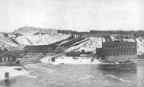
DURING last year the Shawinigan Water & Power Company completed its second hydroelectric power development at Shawinigan Falls, with transmission lines and a substation in Mont real. This new power plant is located about 600 ft. from the first power house and is on the banks of the St. Maurice River, near the gorge, above which the St. Maurice River flows over a precipice, giving a difference between upper and lower levels of about 140 ft. This second development furnishes an interesting illustration of the progress made in hydroelectric power developments and transmission during the last ten years, as it embodies the latest improvements in the hydraulic and electric fields.
The St. Maurice River is one of the largest rivers of eastern Canada, having a drainage area of 17,000 sq. miles. The original power development at Shawinigan Falls included the canal. 100 ft. wide, a bulkhead with six penstocks and the power house. In the second development just completed use is made of the same canal, which has been enlarged at the end to a forebay, closed up by the new bulk head constructed at an angle of about 30 deg. with the old bulkhead and adjoining it.
| |||
| Fig. 1--General View of Hydroelectric Developments of Shawinigan Water & Power Company, Shawinigan Falls, Quebec. |
For improving the water conditions for the new development the water level in the upper bay will be raised about 15 ft. by means of a movable gate dam located across the St. Maurice River, just above the falls. This movable gate dam is at present in course of construction, and consists of twenty stony sluicegates having a clear opening of 40 ft. and a height of 18 ft. These gates will be operated electrically by means of three traveling hoists running on a bridge supported on the concrete piers. Two regulating gates of the same type, 16 ft. wide and 18 ft. high, inclosed in a building and equipped with a heating system, will be provided to regulate excess flow of the river during the cold season.
BULKHEAD AND GATE HOUSE.
The general lay-out of the old and new bulkheads, with penstocks and new power house, is shown in Figs. 1 and 2. The new bulkhead was built with a view to eliminate the troubles which are caused in this northern climate by ice, to procure the best possible construction to maintain an uninterrupted flow of water to the turbines, and to give all the facilities necessary to inspect and repair any part under water, without interfering with other parts of the bulkhead.
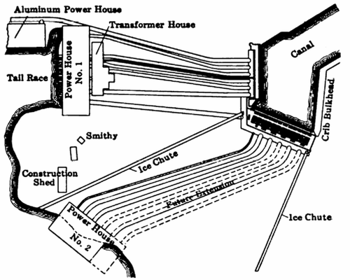 |
| Fig. 2--Plan of Development at Shawinigan Falls. |
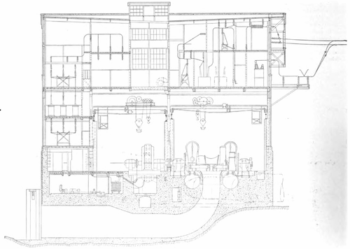 |
| Fig. 3--Cross-Sectional Elevation of Station No. 2. |
| |||
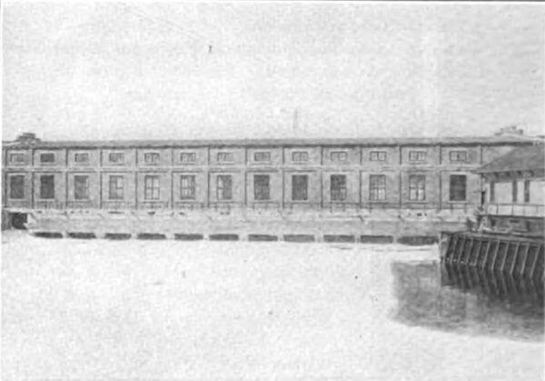
| Fig. 4--Forebay Showing New Gate House and Portion of Old Gate House. |
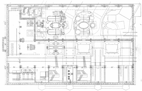 |
| Fig. 5--Plan View of Station No. 2. |
The bulkhead is built entirely of reinforced concrete and steel, and provision is made for five 14-ft. penstocks and one 4-ft. penstock to the exciter. The width of the bulk head at the bottom is 60 ft., the height from the rock to the operating floor 40 ft., and the length of the structure 225 ft. Each unit is complete in itself and independent, straight through from the bulkhead, penstock, turbines, generator, transformer, transmission line and step-down transformer at Montreal.
The water enters the bulkhead under a submerged arch, passes through the front gates, then through the racks and the main penstock gate. Each unit in the bulkhead is separated from the other by a reinforced partition wall, forming with the front gate and main gate of the penstock an independent chamber, of a width of 27 ft. at the entrance, and decreasing in width toward the penstock entrance. These partition walls are 34 ft. high, and are designed to stand the full water pressure when the chamber is empty and the adjacent ones are full. The gates which separate the chamber from the forebay are made in three parts, one above the other, linked together, and are detachable in order to facilitate removal by the traveling crane. The racks are constructed at an angle of 60 deg. to the horizontal, are supported by the steel construction incased in concrete, and are designed to stand a pressure equivalent to 80 per cent of the depth of the water. The rack is divided horizontally into two parts, which are linked together and can be lifted out of the water by means of the crane. The rack is composed of bars 31½ in. by 5/16 in., with a clear opening between the bars of 24 in. The bars are fastened to a very rigid framework of channels and angles, which construction provides for the safe handling of the racks without any danger of bending or collapse in removing them from the chamber.
| |||
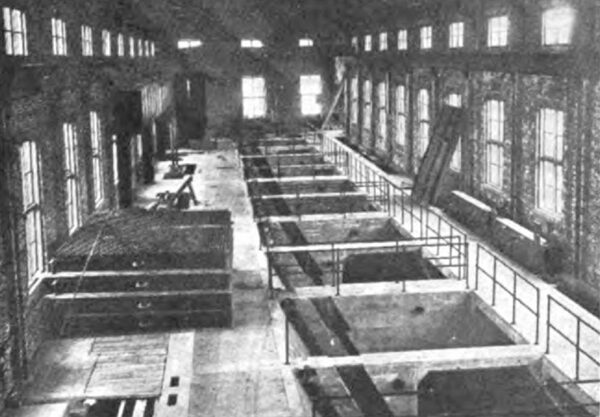
| Fig. 6--Interior of Gate House. |
| |||
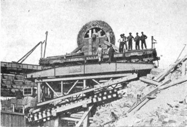
| Fig. 7--Skidway Car Taking Rotor Down Hill. |
The velocity of the water passing into the chambers at the bulkhead is about 2.5 ft. per second. The velocity through the racks is 2.3 ft. and at the penstock entrance 8.5 ft. per second. The concrete walls of the chambers are nicely rounded, and an effort was made to change the velocity of the water as gradually as possible in order to prevent the usual eddies and loss of head which are present in many power developments where care is not taken in this important part of the design.
GATE-HOUSE HEATING SYSTEM.
The gate-house building is provided with a 25-ton crane, by which means the front gates, racks and stop logs are manipulated. The design of the heating system of the gate house is somewhat novel. In the construction of the building air ducts 12 in. in diameter are provided in the floor and extending the whole length of the gate house, with laterals leading across the building. Openings are provided in the chambers so that air can be discharged in many places throughout the gate house and actually blown down against the steel work in the different chambers.
A large fan is provided in one end of the building, having a capacity of about 60,000 cu. ft. per minute, and driven by a 50-hp motor. The air is taken into this fan through a vertical intake, the air being taken in up toward the top of the room. In this intake are provided electric heaters, which consume about 300 kw. The air coming into the intake is heated by this arrangement, passes through the fan at a temperature of about 60 deg. C. and is blown out in many places around the gate house and especially against the top of the racks and the steel work at the side of the gates.
The mean temperature at Shawinigan Falls falls below freezing point usually early in December and, with the exception of occasional thaws, stays below freezing point until the middle of March. The minimum temperatures are reached toward the end of January and beginning of February, when there is usually experienced a continuous temperature of from 10 deg. to 30 deg. below zero for several days. As a result of this, the formation of ice in the St. Maurice River is such that during the course of the winter about 24 in. of ice is formed, and in still, protected places the ice is found much thicker.
In the early days of the power development at Shawinigan Falls it was found that the severe weather caused very great difficulties in the operation of the gates owing to the formation of ice on the gate mechanism, etc., and it was very difficult to get the racks clear owing to the fact that the steel conveyed the heat from the water to the air, and thus the steel was very slightly lower in temperature than the water which was against it. This resulted in the formation of ice and in the sticking of floating ice to the racks, interfering with the operation of the power plant. Experience would indicate that if the steel work above the water could be maintained at a higher temperature than the water the above effects would not be so pronounced. The result of the elaborate heating system which was put in seems to have justified expectations, as there has been no ice formation inside the building and no tendency of the ice in the water to stick to the rack bars. Further, the ice has not formed around the gates, and consequently no difficulty has been experienced in operating the headgates in the most severe weather.
PENSTOCKS.
The penstocks which connect the bulkhead to the power house located on the lower level are 14 ft. in diameter and about 600 ft. long. They are carried in steel saddles placed 12 ft. apart, center to center, the saddles being supported by three concrete piers. The penstocks are made of open hearth steel sheets varying in thickness from 3/8 in. to 7/8 in. at the power-house end. The 4-ft. diameter penstock is made throughout of 3/8-in. plates. Inside the power house, immediately in front of each water turbine and below the main floor, each penstock ends in two branches, forming the connections to the two cases of the double spiral turbines. The average velocity of the water at full load in the 14-ft. penstock is 8.5 ft. per second, and from the data which the writers have the loss in head due to bends and friction in the pipe at full load on the turbine is 1.73 ft.
GENERATING EQUIPMENT.
The lay-out of the plant when completed will be such that there will be five units provided in the power house, but the present building provides room for three units, two being at present installed. Each unit has a normal rated capacity of power delivered from the electric generator of 16,000 hp, giving the station a total capacity of 80,000 hp. This rating is based on a 35-deg. temperature rise of the generator, but provision is made for the generator to operate safely with 45 deg. rise of temperature, and under these conditions to deliver approximately 20 per cent more power, so that in case of emergency the plant can be operated to give about 90,000 hp or 100,000 hp at a power factor of 85 per cent.
| |||
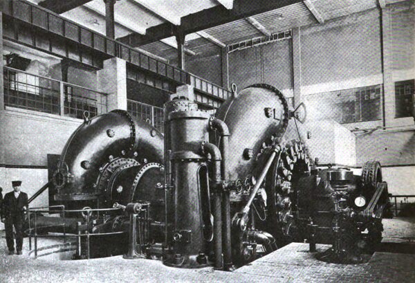
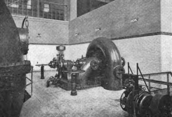
| Fig. 8--Main Turbine, Power House No. 2. |
The general scheme of the lay-out is to divide the power station in two divisions, each consisting of two units, with the third unit in the center, which is considered as a spare and can be applied in case of trouble to either set of units. The width of the building is 115 ft., length 180 ft., and height from the bottom of foundation to roof is 112 ft.
The power house is built entirely of reinforced concrete, brick and steel. The walls inside are faced with pressed buff brick, and up from the floor to about 10 ft. with glazed enameled brick. The floor is tiled with English red quarry tiles and conforms with the general interior finish of the power house to give it a neat and bright appearance.
Apart from the generator and turbine rooms, the building contains a complete washroom with shower baths for the men, one bedroom, locker room, office for the superintendent, test room and telephone central station for local and private telephone lines. The machinery rooms are lighted with 400-cp tungsten lamps, fixed directly to the ceiling. All hydraulic machinery is separated from the electrical machinery in the power house by a reinforced concrete wall 16 ft. high. The units are arranged at right angles to the long axis of the power house and are placed 40 ft. distant, center to center. The generators and turbines each have separate cranes-for the generators one of 100 tons capacity, and for the turbines one of 50 tons capacity. This double arrangement of cranes was of great advantage, as it saved considerable time in the erection of the machinery.
| |||
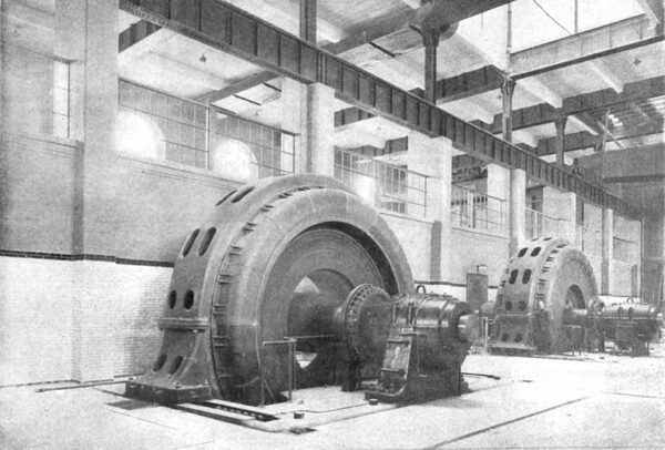
| Fig. 9--Main Generators, Power House No. 2. |
The main turbines are of the twin spiral-case type, receiving the water at the bottom of the case and each case discharging inward to central draft chest. The rating of the turbine is 18,500 hp with an effective head of 145 ft. at 225 r.p.m. The turbines are controlled by movable guide vanes with an outside moving mechanism, operated by the governor engine through a heavy crank shaft and connecting rod. The vanes and runners are made of cast steel. Each turbine is provided with an automatic governor and governor engine, operated by water at 200 lb. pressure. The wheel can also be controlled by hand with water pressure. There is further a device provided to operate the governor engine by a small hand pump. This arrangement is considered in the nature of an emergency apparatus and is not intended to operate the gates quickly.
| |||
| Fig. 10--Exciter Turbine, Power House No. 2. |
Each turbine is provided with relief valve located between the two spiral cases below the main floor of the power house and forming a part of the V-shaped penstock connection. The shaft operating the gates of the turbine also operates the relief valve in such a way as to provide a positive movement of this valve, so that the turbine gates cannot close suddenly without opening the valve, and when the relief valve is so opened it will gradually close at such a time as will prevent a rise of pressure in the penstock exceeding 25 per cent of the normal pressure. The relief valve is capable of discharging at least 1000 cu. ft. of water per second, and it discharges directly into the tailrace.
| |||
| Fig. 11--Motor- Driven Exciter. |
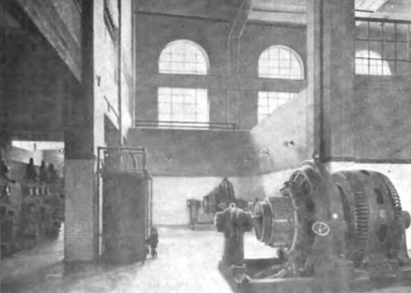
Each turbine is directly coupled to a three-phase, 14,000 kva generator wound for 6600 volts, 60 cycles. The rotating part of the generator weighs 198,000 lb. and the flywheel effect is 4,500,000 lb. at 1-ft. radius. Each generator can be connected either to a low-tension busbar system or directly to a three-phase, 14,000-kva oil-insulated, water-cooled transformer, which raises the tension from 6600 volts to 100,000 volts.
TRANSFORMERS.
The transformer can be connected on the high-tension side to two busbar systems. The busbar systems are provided with sectionalizing switches, so that each unit with its transformer can be connected directly to its 100,000-volt transmission line.
| |||
| Fig. 12--Low--Tension Switchroom and Main Transformer. |
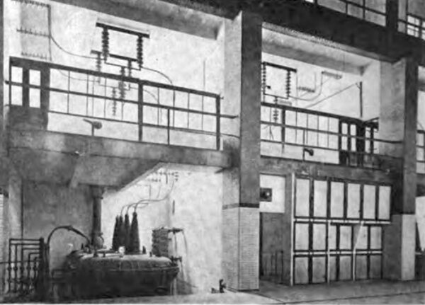
There are at present two step-up transformers installed in the power house located on the basement floor 11 ft. below the main floor on the tailrace side. By removing the main floor in front of the transformers it is possible to move the transformers out under the cranes of the generator room for inspection or repairs. The outside dimensions of the transformers are 23 ft. x 9 ft., with a height 18 ft. from the bottom to the top of the high-tension terminals. The weight of the transformer is 260,000 lb. complete. The case contains 10,000 gal. of oil. The cooling water required for the transformer is 56 gal. per minute. The transformers are designed to stand a test voltage of 275,000 volts for one minute between high-tension coil and core. They are Y-connected on the high-tension side and delta-connected on the low-tension side, with a neutral connection on the high tesion side grounded to 100-ohm grid resistor.
In this ground circuit are connected a recording am meter and a relay to operate the high-tension line switches, should the current in the neutral rise to a dangerous value.
REACTORS.
Between the transformer and generator is connected a reactor coil of twenty-two turns, made up of 2,000,000-circ. mil bare copper cable wound on a hard-wood form. No iron was used in the construction of these coils, all metal parts being of brass. The reactance of this reactor, together with the reactance of the generator, transformer and transmission line, serves to reduce the short-circuit current on the whole system. The combined reactance of the generator, reactor coil and transformer is in the neighborhood of 23 per cent, that is to say, at normal full-load current it consumes 23 per cent of the normal rated voltage.
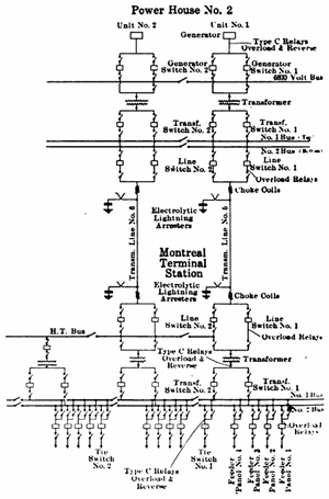 |
| Fig. 13--Circuit Connections of Entire System. |
BUS ARRANGEMENT.
The low-tension busbars with oil switches and disconnecting switches are installed separately for each unit in a concrete structure opposite each generator on the main floor, and the cells containing the disconnecting switches and shunts and series transformers are provided with asbestos doors. The high-tension 100,000-volt circuits are made up entirely of 1-in. copper tubing. The high-tension disconnecting switches and oil switches take up the space on the floor above the generator and turbine room.
SAFETY MEASURES.
The whole high-tension wiring is laid out in such a way as to afford the greatest safety for the operating force and to eliminate as much as possible mistakes in the operation of disconnecting switches. The high-tension disconnecting switches form a horizontal bar which bridges a gap of 3 ft. 6 in. of the high-tension circuit. They are operated mechanically, by means of a shaft, gears and chain, from outside of the room where they are located and at a point remote from any live conductors. Each high-tension oil switch is also located in a separate chamber, and when the disconnecting switches on both sides of such an oil switch. are opened the wiring above and around the oil switch is dead and the oil switch can be inspected and dismantled without danger.
| |||
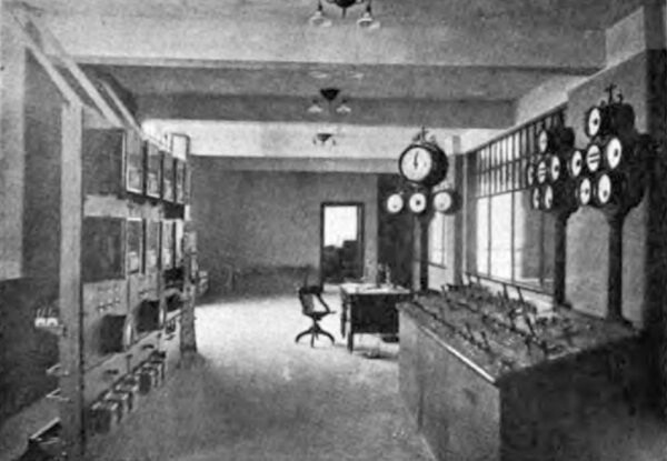
| Fig. 14--Control Room, Station No. 2. |
| |||
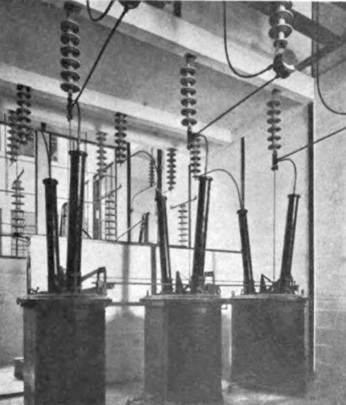
| Fig. 15--100,000-Volt Line Circuit- Breaker. |
All disconnecting switches on the high-tension and low tension busbars are equipped with a telltale lamp system, indicating the "open" and "closed" position of the switches on the benchboard in the switchboard room by small telephone lamps. The "open" and "closed" positions of the oil switches are also indicated by signal lamps at the place where the disconnecting switches belonging to such oil switches are operated. The main switchboard is located on an inclosed gallery at the end of the power house and is of the benchboard type with dummy buses, with indicating instruments on pedestals in front of each benchboard and recording instruments on a panel at the back of the bench board.
EXCITATION SYSTEM.
Below the switchboard gallery on the main floor are located 125-volt exciter buses and the direct-current switchboard, and in front of it the two exciters, of 400 kw capacity each, one exciter being driven by a 750-hp spiral case tur bine and the other by a 440-volt, three-phase motor, pro vision being made for an additional turbine exciter to be installed. In connection with the exciter system two Tirrill regulators are installed.
AUXILIARY EQUIPMENT.
All auxiliary motors in the power house are of the direct current type; alternating current is used only for heating purposes. For cooling the power house in summer a tunnel connecting the generator pits with the outside of the power house is installed and equipped with a fan to blow the air under the generators. The ventilation in the power house is assisted by a ventilating shaft of 18 ft. x 16 ft., just above each generator, which passes through the upper part of the power house through the roof and ends in a skylight. To facilitate communication between the different floors a combined passenger and freight elevator was installed.
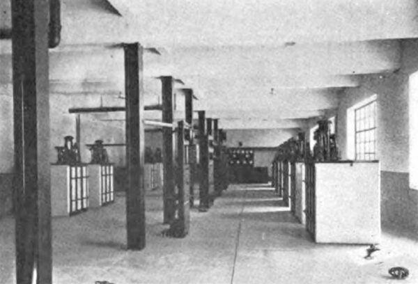
| |||
| Fig. 16--Switchboard Room and Oil Switches. |
Of other auxiliary equipment in the power house, mention might be made of an intercommunicating telephone system, signal system between benchboard and turbine room, compressed air and vacuum system for cleaning purposes, filtering system for pressure water for the governors, oil filter system for the transformer oil, and sterilizing system for drinking water. To take care of any leaks from the turbine or from water in the tailrace, a draining system in the basement of the power house with a 100-hp motor-driven and a 100-hp water-driven centrifugal pump is installed.
An interesting problem which came up in connection with the construction of the power house was the handling of the steel work and machinery-in fact, everything in the power house-from the railway siding to the power house. The power house is located at an elevation about 130 ft. below elevation of the siding and about 600 ft. distant. An inclined railway between the railway siding and power house was built and equipped with a special inclined car, combined with a turntable on the top. The freight cars were run from the siding directly on this inclined car and lowered down hill by means of a steel cable operated by an electric motor. After the inclined car arrived at the lowered position the freight car was turned around by means of the turntable and pulled in the power house under the cranes for unloading.
This arrangement worked very satisfactorily and proved a great economy of time and labor.
RAPIDITY OF ERECTION.
The cofferdam for the new power house was started in September, 1910, and the excavation and steel work for the foundation were carried along during the following winter. At the time of the spring flood the concrete work was well above the water, that is, about 40 ft. above the rock foundation, so that the work was not interrupted. By the middle of June two cranes were erected and in operation, and on Sept. 1, 1911, the first unit, consisting of turbine and generator, was erected ready to run. The commercial operation of the power house was started Nov. 13, 1911.
