[Trade Journal]
Publication: Electrical World
New York, NY, United States
vol. 59, no. 19, p. 1015-1019, col. 1-2
NEW HYDROELECTRIC PLANT OF THE SHAWINIGAN WATER & POWER CO.-II.
100,000-Volt Transmission System of the New Hydroelectric Development at Shawinigan Falls and Substation Details.
87-Mile Transmission Line Erected in Seven Months-Construction Details of Steel Tower Line Carrying 19-Strand, 250,000-Circ. Mil Aluminum Conductors-Substation Transforming and Auxiliary Equipment-Safety Measures.
BY JULIAN C. SMITH AND F. T. KAELIN.
DURING last year the Shawinigan Water & Power Company completed its second hydroelectric power development at Shawinigan Falls, with transmission lines and substation at Montreal. This new plant was described in the issue of May 4. The present article gives a description of the transmission system and the substation.
TRANSMISSION LINE.
The two 100,000-volt transmission lines from Shawinigan Falls to Montreal have each a normal capacity of 12,500 kw. The transmission line is 87 miles long and is erected on a private right-of-way 100 ft. wide, with 867 steel towers. The three wires of each circuit are arranged in vertical plane on each side of the tower and carried on suspension insulators. The vertical spacing of the wires is 8 ft., and conductors consist of 19-strand aluminum cable, 250,000 same general construction and dimensions as the light towers. Their weight is 6200 lb. The towers are made up entirely of open-hearth steel, hot-galvanized. All the fit tings and bolts used in connection with the towers are also galvanized. The light towers are designed to stand a breast pull of 15,000 lb. applied across or along the lines at the Fig. 18-Section of Transmission Line. intersection of the upper cross-arm at the level of insulator supports, and the heavy-section towers will stand a pull of 30,000 lb. The light-section towers have been used in spans up to 650 ft. and on angles less than 2 deg. For circ. mil. For lightning protection two galvanized stranded steel cables of 38-in. diameter are strung on the top cross arm of the towers about 32 ft. apart.
| |||
| Fig. 17--Transposition Tower. |
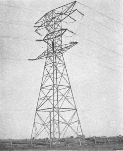
TOWERS.
There were two types of standard towers used, a light section tower and a heavy-section or strain tower. The standard distance between towers is 520 ft., but there are spans across the rivers up to 1400 ft. with special high towers. Every tenth tower is a strain tower. The insulators on the strain towers are of the same type as the regular suspension insulators, but of eight units instead of seven. The standard tower has a total height of 70 ft. 7 in. and at the base is 19 ft. x 19 ft. square. It weighs 4800 lb. The strain towers are a little shorter, but otherwise of the same general construction and dimensions as the light towers. Their weight is 6200 lb. The towers are made up entirely of open-hearth steel, hot-galvanized. All the fit tings and bolts used in connection with the towers are also galvanized. The light towers are designed to stand a breast pull of 15,000 lb. applied across or along the lines at the intersection of the upper cross-arm at the level of insulator supports, and the heavy-section towers will stand a pull of 30,000 lb. The light-section towers have been used in spans up to 650 ft. and on angles less than 2 deg. For longer spans and greater angles heavy-section towers have been used, and for angles greater than 60 deg. special angle towers have been used.
| |||
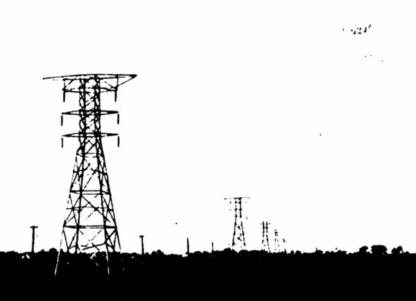
| Fig. 18--Section of Transmission Line. |
| |||
| Fig. 19--Combination Tower. |
Each tower is grounded with a copper wire connected to the steel by means of a Dossert rail bond. The ground plate consists of a copper plate embedded in pulverized charcoal. All steel towers are anchored on each leg to a concrete foundation 6 ft. deep and 3½ in. square at the bottom, tapering to a square or round top of about 15 in. in diameter. The tower legs are bolted to this concrete foundation with two 18-in. steel bolts, which extend the whole length of the 6 ft. of concrete foundation.
The foundations for the strain and special towers are of the same type, but proportionately heavier. The maxi mum sag for the standard span is 21½ ft. and the minimum clearance between wire and ground 24 ft. In stringing wires dynamometers have been used to check the actual stresses with the calculated stress and also to determine sag at certain temperatures. For the long spans across the river No. 000 B. & S. copper cable has been used in order to decrease the sag.
The work on the transmission line was started at the end of February, 1911, and completed Oct. 15, and power at 100,000 volts was transmitted for the first time on Nov. 9, 1911.
SUBSTATION AT MAISONNEUVE.
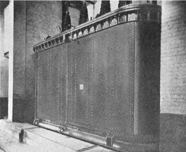
At the end of the two transmission lines a substation for reducing the tension to 12,500 volts was erected. This substation is located on Orleans Avenue in Maisonneuve, a suburb of Montreal. The two transmission lines enter the building through projecting hoods. The general lay-out of the high-tension wiring, circuit-breakers, disconnecting switches, etc., is similar to that in the power house. Each transmission line with its high-tension wiring in the station, step-down transformer, low-tension busbar, etc., forms a separate unit, and its apparatus are separated from those of the other units by partition walls. The substation is built for three three-phase, 12,500-kva transformers to step down the tension from 85,000 volts to 12,500 volts. At present only two transformers are installed.
| |||
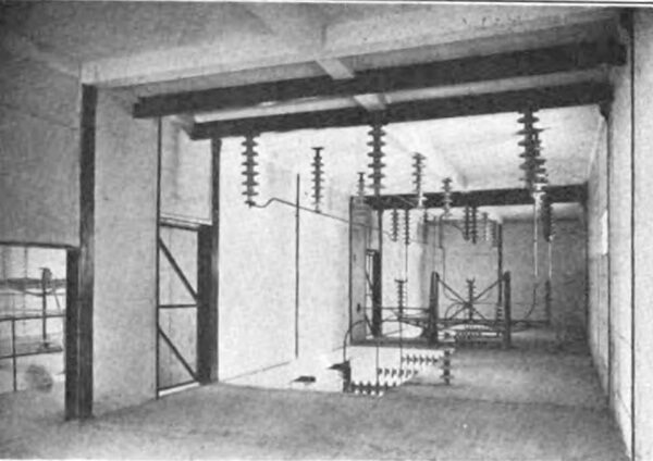
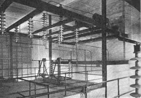
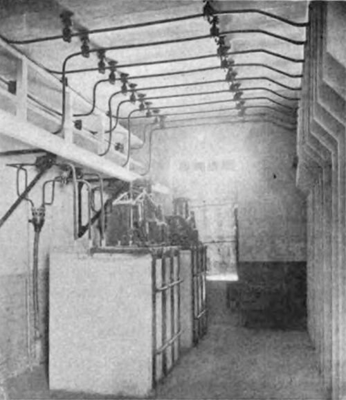
| Fig. 20--High-Tension Busbar Room in Terminal Station at Maisonneuve, Montreal. |
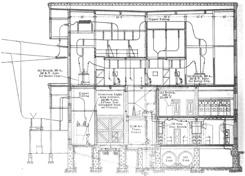 |
| Fig. 21--Elevation of Terminal Station at Maisonneuve, Montreal. |
The station is equipped with a 75-ton hoist to facilitate the handling of the transformers. The transformers can be rolled out by means of a truck to the end of the building where this hoist is installed. The first floor of the station is occupied on one side by transformers and electrolytic lightning arresters and on the other side by 12,500-volt buses and disconnecting switches for the feeders.
SUBSTATION BUS STRUCTURE.
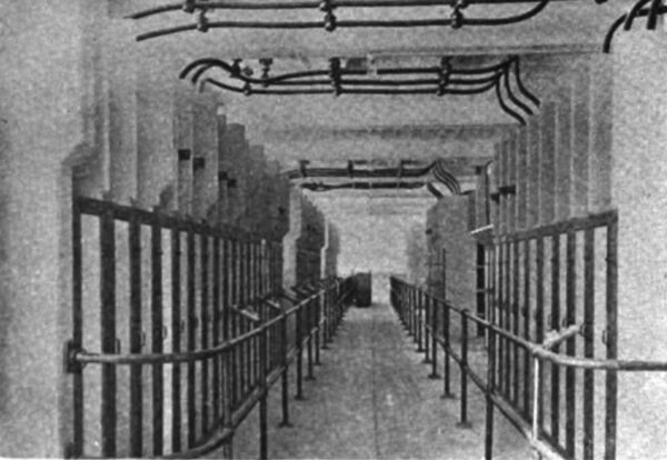
These low-tension busbars are separated from each other and from the adjacent bars by heavy concrete barriers. All parts of the equipment, such as busbars, busbar chambers, etc., are covered by asbestos doors, which are locked in position, but which can be readily removed in case it is necessary to get inside the busbar chambers. The busbar chambers and disconnecting switches are designed so that the only exposed live parts are not less than about 8 ft. from the floor. There is ample room for a man handling these knife switches to get a sufficient distance away so that in case of trouble he will not be injured.
SUBSTATION SAFETY MEASURES.
Another detail involving the safety of the operators and the proper operation of the station is the locking of the 12,000-volt switches. The ordinary knife switches may be thrown open by reason of the reaction which takes place between the current passing through the blade and the magnetic field which is generated around the blade. These switches are occasionally opened up at the time they carry the maximum current, and the results are that the switches and the surroundings are often very badly damaged by the intense heat of the arc. This lock-type switch is locked in the closed position by a kind of wedge, which at the same time forces the contacts together and thereby assures that the switches will operate at a low temperature and will not be thrown out under heavy current.
CONTROL.
The main operating room is on the second floor. Here the operator controls the transformer circuits, the 100,000 volt oil switches on the transmission line and transformers from the benchboard. Directly behind the operator are mounted totalizing panels which show by indicating and graphic recording meters the total amount of power sup plied by each transformer unit to the outgoing feeders.
| |||
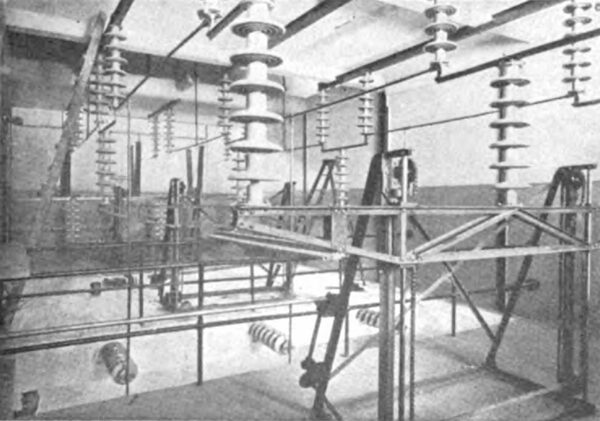
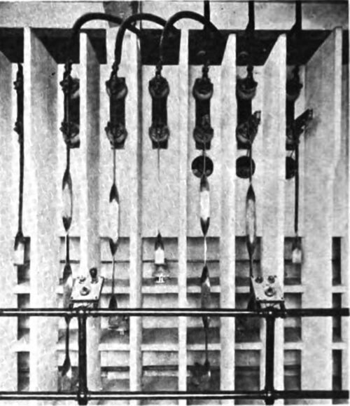
| Fig. 22--Line Entrance Bushings, Disconnecting Switches and Choke Coils. |
Mounted along the room opposite groups of feeder switches are the panels controlling the different feeders. Each of these feeders is equipped with a little device which, if the switch trips out. will light a lamp on the benchboard and at the same time ring the bell to bring the operator's attention to the fact that the switch has tripped out. There are also two extra panels and two extra oil switches on the 12,500-volt side, which are provided to take care of what are called tie lines between the old terminal station and the new one. The old terminal station is supplied from the old power house at Shawinigan Falls with 30-cycle energy and is equipped with motor generators to change the frequency from 30 to 60 cycles. All the 60-cycle energy from the old and new substation is delivered to the Montreal Light, Heat & Power Company for further distribution. In order to join the two substations together, it is necessary to synchronize the two stations, and therefore the tie switch panels in the new station are equipped with synchronizing lamps and synchroscopes.
| |||
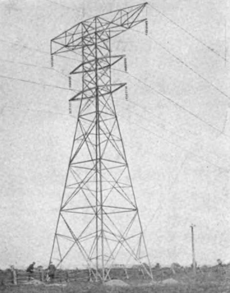
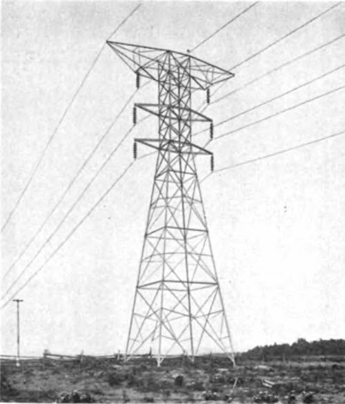
| Fig. 23--Transmission Line Tower, Light Section. |
| |||
| Fig. 24 High--Tension Disconnecting Switches and Oil Switch. |
It is interesting to note that the water-power stations, which are located, measured along the transmission line, a distance of 170 miles apart, are synchronized by an operator in Montreal, who has no control over the voltage and frequency of either station other than by informing the men in the stations as to the conditions desired. As a matter of fact, this synchronizing is done without any difficulty at all, and in two or three minutes after the switches are set ready for synchronizing the final switch can be closed and the two stations operated in parallel.
| |||
| Fig. 25--Auxiliary Transformer Switches. |
| |||
| Fig. 26--12,500-Kva Step- Down Transformer. |
The high-tension wiring consists of 1-in. copper tubing and the low-tension busbar of copper bars 3 in. x 14 in. All the connections between cables, disconnecting switches, oil switches and low-tension busbars, also between disconnecting switches, oil switches and high-tension busbars, are made with Dossert connectors. These connectors form a mechanical connection without soldering. They save considerable labor and time in the erection of the apparatus and afford easy facilities for disconnecting circuits in case of trouble or when temporary connections are required.
SUBSTATION AUXILIARY EQUIPMENT.
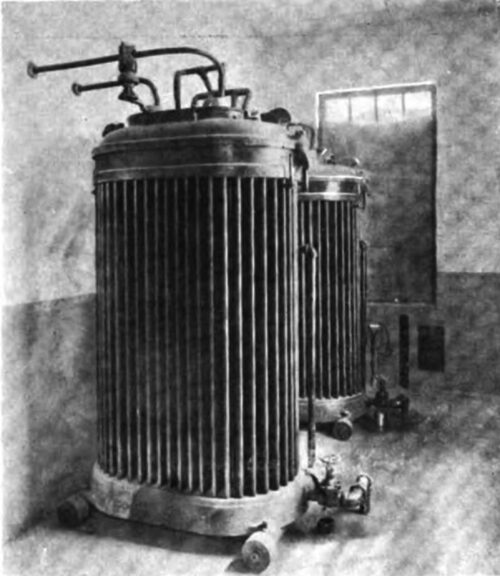
In the basement is located the auxiliary equipment, consisting of a storage battery for operating the oil switches in case of an interruption of the main circuit. This storage battery consists of 66 cells having a normal voltage of 125 volts and a normal discharge rate of 200 amp for one hour. With the storage battery is a small motor-generator set which can be used for the operation of the oil switches or for charging the battery. In the basement also are the oil tanks for transformer oil consisting of six tanks having a capacity of 5000 gal. each. There are also two small tanks for the oil switches and lightning arresters.
| |||
| Fig. 27--Auxiliary Transformers. |
| |||
| Fig. 28--Low-Tension Switchboard. |
The cells in which the high-tension oil switches are installed are provided with sewer connections and provision is made so that in case of an explosion of the tank the oil cannot spread outside the cell but can escape to the sewers. As a part of the equipment for handling the oil there are two pumps, the main centrifugal pump for handling the transformer oil from the tanks up to the transformers and the small filter press outfit for filtering and drying the oil. The pumps for circulating water to the transformer cooling coils are installed in the basement. This water is taken from a tank outside the building to the pumps and is forced through the transformers and back again into the tank, into which it is sprayed for the purpose of cooling it. The substation building is 125 ft. long, 80 ft. wide and 70 ft. high, including the basement, and is built entirely of fire proof material. The steel-work construction is mostly in cased in concrete. The partition walls around the 100,000 volt wiring and oil circuit-breakers are of reinforced concrete, and the outside walls are of brick. The work on this substation was started last April, and the station was put into operation the beginning of November.
SUMMARY.
The main turbines and exciter turbines in the power house were built by the I. P. Morris Company, Philadelphia, Pa.; the generators and exciters by the Canadian Westinghouse Company, Hamilton, Ont., and the step-up and step-down transformers by the General Electric Company, Schenectady, N. Y. The penstocks were made and erected by the John Inglis Company, Toronto, Ont., and the cranes in the power house, gate house, substation and the skidway car and hoist were furnished by the Whiting Foundry Company, Harvey, Ill. The aluminum cables for the transmission line were made by the Northern Aluminum Company, Shawinigan Falls, Quebec, and the insulators by the Ohio Brass Company, Mansfield, Ohio. The transmission-line towers were furnished by the Canadian Bridge Company, Walkerville, Ont.
| |||
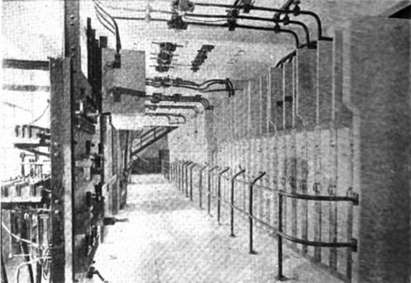
| Fig. 29--Feeder Disconnecting Switches and 12,500-Volt Buses. |
| |||
| Fig. 30--Feeder Disconnecting Switches. |
The complete hydroelectric plant was designed and built by the engineering staff of the Shawinigan Water & Power Company. The following are the principal engineering officers of the Shawinigan Water & Power Company: Mr. Julian C. Smith, chief engineer; Mr. F. T. Kaelin, assistant chief engineer; Mr. R. J. Beaumont, chief draftsman, and Mr. John Morse, operating superintendent.
