[Trade Journal]
Publication: American Electrician
New York, NY, United States
vol. 9, no. 11, p. 425-427, col. 3,1-3,1
INSULATOR AND CABLE TESTING, WITH
SUGGESTIONS FOR NEW
APPARATUS.
BY N. MONROE HOPKINS, A. I. E. E.
The testing of insulation may be conveniently divided into two branches or systems; the break-down or puncture test and the actual measurement of electrical resistance in ohms.
In the testing of porcelain and glass insulators designed for long-distance power transmission, certain classes of railway work and all lines for high electrical tension, the break-down test prevails, and in many instances is preferable to careful galvanometer measurements in the testing of insulation on wires and cables. The puncture test may again be divided into the dry and the wet test, the latter being far more severe for very obvious reasons.
The difference of electrical potential brought to bear on insulators and cables varies, of course, with the thickness of the walls, in the case of porcelain insulators, and with the thickness and composition of the covering on wires and cables. In testing porcelain insulators a voltage of 40,000 for a period of forty minutes would be a good test for insulators whose walls are at least 1 in. in thickness. For insulators with walls 1/2 in. thick, 30,000 volts for forty minutes would be a good and severe test.
When an insulator remains intact when subjected to a test of approximately this severity, it is usually pronounced perfect. This, however, should not be the case, for many insulators undergo this tension without cracking or breaking in any way, for the presence of a conducting mineral in the clay carries the current. These faulty insulators can at once be detected, as they become intensely heated in the neighborhood of the conducting mineral. They are, however, in many cases, unjustly shipped with those that remain unaltered and cold, partially because they are not discovered, as they make no buzzing sound like the cracked ones, and partially because of the ignorance of the man in charge.
Again, a test of this character is not a fair one if several heated insulators are allowed to remain on the testing table with the others, for the conducting minerals in the faulty ones only furnish electrical paths, or equalizing paths, across the high-voltage feed wires, with a result at once apparent.
The method of holding the insulators on the testing racks or tables is frequently also very faulty, as the electrical stress is frequently not applied where it will eventually come in practice when the insulators are called upon to support a high-tension line wire. High-potential, long-distance lines are developing quite rapidly, and leaks due to faulty insulators only mean the combustion of additional pounds of coal in the generating station, or a smaller output in the case of turbine units.
 |
| Fig. 1. — Diagram of Connections. |
It is the wish of the writer to describe here some methods of insulator and cable testing which may be made as severe as may be necessary for all purposes, bringing the electrical stress right when it will come in practice. The writer also offers one or two suggestions which may prove of assistance to those who wish to experiment along lines of this character. This puncture testing requires great carefulness, as carelessness in handling a testing laboratory of this class would obviously result in fatal accidents.
Fig. 1, represents an alternator designed for 1000 volts, with diagram of connections. A "step-down" transformer is introduced, lowering the voltage to 100, giving a convenient line current for the measuring instruments. A controlling or "choking" coil is included next, whereby the voltage is slowly raised. An oil immersion transformer, or group of ordinary transformers designed to give the proper raise in voltage, is located in a safe and convenient place. The approximate voltage may be ascertained by taking readings from the instruments and estimating for the transformers, or by a table of spark-gaps.
Tables on spark-gaps are only very approximate, as the gap will vary with dry and damp weather. For a 30,000-volt test, the spark-gap should be set at 1 1/2 ins. on an average day. Any appreciable rise in voltage will cause a discharge to take place across the gap between the sharp points or needles. By referring to spark-gap tables and comparing the readings of the instruments, taking correct consideration of the transformer, the voltage may be learned quite near enough for testing purposes, as with a set spark-gap once established all insulation subjected on days of equal humidity will receive the same breaking-down strain.
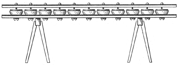
Fig. 2 shows a side view of a testing table with an iron top, with punchings to receive the insulators. A table wide enough for two or three rows is the usual practice, having a capacity for about forty insulators at a time. It will be readily seen that the electrical stress is all between the end of the iron pin which rests in the insulator, and a circle described about the outside, where the circular punching supports it. This is a common type of testing table now in use. As of possible interest to those who have not witnessed a practical test of this character, the behavior and condition of things during and after the run of thirty minutes will be described.
 |
| Fig. 2. — Ordinary Form of Rack for Testing Insulators. |
Let us consider this common type of table with the circular holes with forty insulators. The generator is started and the switch over the transformer closed, with the controlling coil thrown well over for the maximum "choking" effect. The instant the switch is thrown, a deep and loud humming noise is produced, changing intone from a "singing " to a harsh buzzing, until an insulator cracks or punctures, when a shrill piercing sound is emitted, accompanied, by the liberation of ozone, which is more or less noticeable from the time the switch is first thrown. The poorly baked and faulty insulators go to pieces within five minutes and those of a little better glaze, or more perfect baking do not follow much before fifteen or twenty minutes. During the remaining ten minutes of a test of about one-half hour very few, as a rule, puncture.
 |
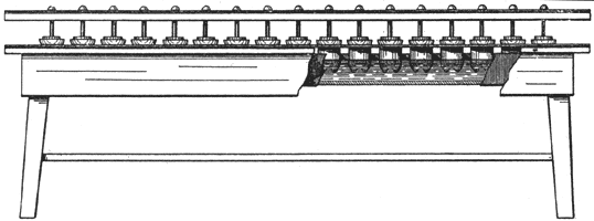
| Fig. 3. — Immersion Form of Rack for Testing Insulators. |
Of course, when an insulator punctures its presence and location on the table is detected by its loud singing and the presence of a glow when it is in contact with the table top. The "choking" coil is thrown over and the switch opened and the punctured insulator and its iron pin are removed. The fatality among carefully made insulators is from 8 to 10 per cent. when subjected to 30,000 volts, when their walls are no more than 1/2 in. thick. Of course, these figures will vary somewhat with different clays and bakings, etc.
Fig. 3 represents an immersion table designed by the writer with which he has as yet made no experiments. With a strong solution of salt in the tank, it is readily seen how "searching" and severe a test on this table would be, especially if the insulators were partially filled with brine to insure electrical stress on every point of the inside wall.
 |
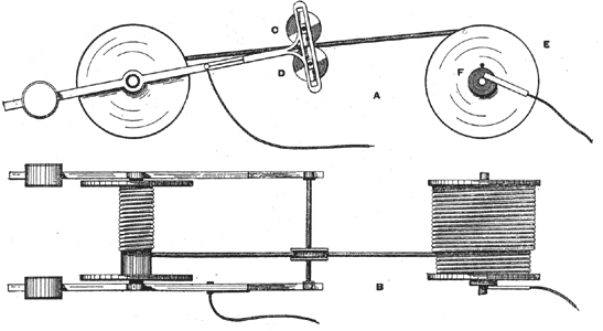
| Fig. 4. — Cable Testing — Dry Method. |
Fig. 4 represents a contrivance, which as yet is only the writers' suggestion, for testing the insulation on wires and cables as they are wound from one drum to another, A being a side wire and B a plan. The grooved wheels C, D, with little sliding blocks for bearings, are kept against the cable by small springs, not shown in the drawing. The weighted arms are of wood until near the end, where the metal slotted guide joins. The conductors of the cable are brought out through a hole in the spool, E, and connected with the plate, F, which is in contact with the sliding brush. The entire electrical stress or puncturing tendency is brought to bear directly on the insulation between the conductors and the grooved wheels, which nearly encircle, or embrace, the cable. The pulleys are loose on their axles so they may follow the cable as it winds or unwinds from the drums. By virtue of the pivoted arms the wheels are able to keep to the cable as it rises or lowers because of the different layers on a drum. As this illustration is intended to be entirely of a suggestive character it is, of course, subject to modification to meet the requirements of specific cases.
 |
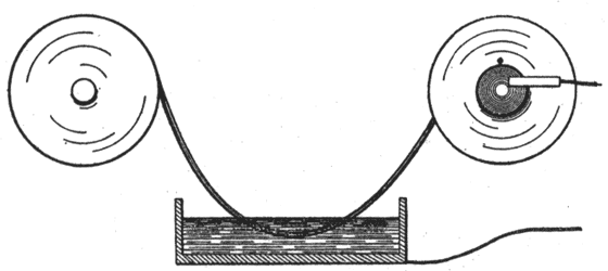
| Fig. 5. — Cable Testing — Wet Method. |
Fig. 5 shows a much simpler method of applying the stress to the insulation. As it would be undesirable to wind the cable on the drum after passing through brine without wiping and drying, some means to effect this should be devised without endangering the attendant.
