[Trade Journal]
Publication: American Electrician
New York, NY, United States
vol. 10, no. 2, p. 51-55, col. 1-3
BUTTE, MONTANA, ELECTRIC POWER TRANSMISSION PLANT
THE MONTANA POWER COMPANY.
BY L. D. TANDY
| |||
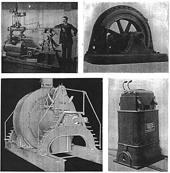
| Fig. 1. Water Wheel Governor. Fig. 2. 750 K. W. Generator. Fig. 3. Type of Turbines. Fig. 4. 250 K. W. Transformer. Generating Machinery and Transformer. |
The Montana Power Company, which was organized Aug. 10, 1897, will have, when ready for practical operation, a plant that will rank among the finest in the United States, not only from an engineering but from a financial standpoint. The plant was projected, financed and built upon a different basis from any other of a similar character in the country, the entire proposed output having been contracted for before ground was broken. Thus the problematical feature as to the income to be derived from the enterprise, was eliminated. The disposition of the power was made on a basis of five to ten year contracts, and at remarkably good prices for both the Power Company and the customers.
 |
| Fig. 5. Plan and Elevations of Power House. |
The coal used in the city of Butte is bituminous, from mines at Rock Springs, Wyo. Its high price ($3.60 per ton) and poor quality constitute one reason why its use for the generation of steam power is expensive. Another important factor in the high cost of steam power at Butte is the scarcity of water. The only way in which water can be obtained for condensing is from the city mains, and its cost, under such conditions, is, of course, prohibitive. It is consequently necessary to run all steam plants non-condensing, although the load factor of many of them is such as would make condensing a great source of economy.
 |
| Fig. 6. Turbine and Governor. |
The promoters of this company in drawing up the preliminary plans, decided to employ only the best material and apparatus obtainable, without any of the embellishments, ornamental rather than useful, frequently included in projects of this character. The first step was to secure the best available engineering advice, and J. T. Fanning, of Minneapolis, Minn., and M. S. Parker, of Great Falls, Mont., were chosen. A careful investigation was then made of the various types and manufactures of apparatus suitable to work of this kind, with a view to the selection of the best hydraulic and electrical machinery that the present market affords.
Location. The power station is located on the Big Hole River, 20.6 miles distant from the city of Butte, Mont. This distance is the total length of the transmission line, which is run in practically an air line from the power station to Butte.
| |||
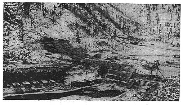
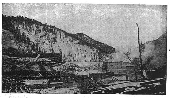
| Fig. 7. Dam, Looking Down Stream. |
Water Rights. The water rights of the company are broad and cover three storage reservoirs above the main dam, as well as a location for an additional power station about 2 miles below the present one. Should it be found necessary, the capacity of the existing plant may be increased by building a second station on the latter site, utilizing the tail water of the present plant by carrying it through an open flume or pipe.
In California, where the laws for the protection of irrigation interests require that the normal flow of the stream be sustained, flood water only can be reserved, or stored. The storage of water in Montana, however, is not restrained by legislation, and when loads are light, water can be stored for use when heavy demands for power are made on the station. The lowest flow in the Big Hole River ever observed was 20,000 miner's inches, and that after a phenomenally dry season.
| |||
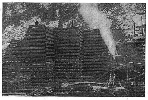
| Fig. 8. Dam, Looking Up Stream. |
Dam. The main dam (Figs. 7, 8 and 9) is a crib, the largest of its kind in the country, being 102 ft. wide at the base and 57 ft. high at the spillway. The total length at the crest is 450 ft., the spillway alone being 200 ft. wide. On the power station side, the dam will rise to a height of 12 ft. above the spillway. 10 in. X 12 inch Montana pine and fir timber in 12 and 16 ft, lengths, held together by 42 in. drift bolts, is used in the construction of the crib. (Fig. 9.) The foundations rest upon bed rock, and the crib is filled with concrete to a point 8 feet above the bed of the river, the remainder of the crib being filled with broken granite.
Two storage dams have been built, one 25 and one 28 miles up the river from the main dam, and a site has also been located for a third. These dams are 30 and 40 ft. high, respectively, and are built on the same general plans as the main dam.
The storage dams and the main dam will impound 2,100,000,000 cu. ft. of water. This will secure an ample reserve for heavy demands during exceedingly dry seasons.
| |||
| Fig. 9. Showing Crib Construction. |
Power Station. The station, which is not yet completed, will be strictly fireproof and built of granite and concrete. The main building is located on the south side of the river, adjacent to the dam. Its ground dimensions are 125 X 78 ft., and the transformer room is 50 ft. X 30 ft. (Fig. 5.) The water will be supplied to the wheels from a forebay in the rear of the station. This forebay is 350 ft. long, 15 ft. wide and 23 ft. deep, and the effective head will be 60 ft. By the use of a forebay instead of a pipe, better regulation will be secured, as all ramming will be eliminated. The connection between the wheels and the forebay will be through a 72 in. penstock, 55 ft. long.
 |
| Fig. 10. Transmission Pole. |
All foundations, both for the water wheels and generators, are on bed rock, and the space between them under the floors will be utilized as a cable tunnel. The roof will be of latticed steel girder, the contract for this and all the other iron work used having been placed with the Gillette, Herzog Company, of Minneapolis, Minn. Three traveling cranes will be installed, two of 16 tons capacity each, running the full length of the main building, and one of 5 tons capacity in the transformer section. These cranes will be furnished complete by the same company.
The building is exceptionally spacious, and is designed to receive five 1000 h. p. units, space being provided for an engine to be coupled to the fifth unit. Neither the fifth unit nor the engine, however, will be installed at present. This engine is designed for use only in times of excessively heavy loads, or when the water supply is abnormally low.
Water Wheels The James Leffel Company will furnish the water wheels for both the generators and exciters. There will be four 66 in. double turbines of the type shown in Fig. 3, directly coupled to the generators and developing 1200 h. p. at an effective head of 60 ft. while running at 180 r.p. m. These wheels are commonly known as the Niagara type and are of the same general design as those which have been installed for the Hydraulic Power & Manufacturing Company, of Niagara the Cliff plant. Fig. 6 shows the details of the wheel and governor construction. The drawings from which the above cut was made have since been slightly changed, in that the intake will be from above the wheel where the air chamber is shown, instead of at the side. Two 36 in. single wheels will be directly coupled to the exciters.
 |
| Fig. 11. High Voltage Insulators. |
Governors. The Lombard water wheel governor will be used, one on each of the generator wheels. From the results obtained with this governor on the Leffel wheels at Niagara, a regulation somewhat better than 2 per cent. is expected with the heaviest fluctuation. Fig. 1 gives a view of the governor. The wheels driving the exciters will be governed by a simple mechanical governor. A special feature of the Lombard governors for this plant is that the water which actuates the primary cylinder is filtered, thereby eliminating any trouble from clogging of the cylinder or parts by sediment in the water. Otherwise they differ in only one important detail from the standard types of governors built by the same company, there being no pumping system connected with these governors, the circulating system being filled with water under flume pressure instead of oil under tank pressure.
In this particular plant the governor builders have specially designed the bed, ratio of gearing and connections in such a manner that the design is integral with the water wheels, of which the governors really become a part, as may be seen from the outline drawing, Fig. 6. These governors not only regulate the speed of the whole plant but also start and stop the plant without manual effort. There are four units like the one shown in the illustrations.
Electric Equipment. The entire electric equipment, both of the power company and of the companies utilizing the power, will be furnished by the General Electric Company, and will consist of four three-phase generators, of a capacity of 1000 h. p. each at their rated load. The generators are revolving field machines having forty poles, and a speed of 180 r. p. m., which gives a periodicity of sixty cycles. The current will be generated at a potential of 800 volts. The generators are practically the same in construction as other machines of the same company built to meet similar conditions, varying only in the number of poles and the speed. The revolving field will be 10 ft. in diameter over all and will weigh 23,500 lbs. A good idea of the general design of the generators can be had from Figs. 2 and 12. All the mechanical construction in these machines is based on a safety factor of twenty, ensuring absolute safety, even in case of a runaway at the full spouting velocity of the water.
There will be two exciters of the multipolar type, having each a capacity of 100 k. w. at rated load, and one exciter can furnish sufficient current to excite the five 1000-h. p. generators. They will be entirely independent in their operation, being directly connected to individual water wheels running at 600 r. p.m., and will operate at a potential of 125 volts.
 |
| Fig. 12. 750-K. Three-Phase Generator, Showing Armature Withdrawn. |
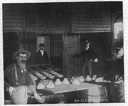
The step-up transformers will be of the air blast type, 12 in number and of 250 k. w. capacity each, and connected in delta. (Fig. 4). The current will be delivered to the low tension side at 800 volts and increased to 15,000 volts for transmission.
In the substation in Butte 2640 k. w. capacity in step-down transformers will be installed of the same design as those in the main station, but of units of various sizes best adapted to the several uses for which they are to be employed. The high tension side of these transformers is wound for 13,250 volts and the low tension side for 2,200 volts.
Both the main station and substation will be provided with two electric blower sets for circulating the air through the transformers. The switchboard will be made of blue Vermont marble and consist of 15 panels, divided as follows:
4 generator panels, 1 main station panel, 1 paralleling panel, 4 high tension transformer panels, 1 exciter panel, 2 line panels, and 2 low tension transformer panels.
| |||
| Fig. 13. Method of Testing High-Voltage Insulators. |
The high tension portion of the main station switchboard will be located in the transformer building in a position where the attendant at the main switchboard can see it at all times.
The panels will be equipped with all of the latest improved instruments, and the station protected with General Electric lightning arresters. All generator and low tension transformer leads will be carried under the floor between the generator foundations, and will be accessible at all times for inspection, as there is ample room for a man to walk through the entire length.
Transmission Line. The transmission line will be 20.6 miles long. The poles will be of Oregon fir varying in length from 33 ft. to 60 ft., with a minimum diameter of 12 ins. at the top, the average length being 40 ft. They are set 105 ft. apart or fifty poles to the mile, and have three cross arms, two 10 ft. 6 ins. in length, and one 3 ft. in length. The two upper or long cross arms are provided with a curved angle iron brace bolted to the pole and to the under side of the cross arms. On the top of the pole and on the ends of the upper cross arm are glass pony insulators on which barbed wire is strung for lightning protection. Glass insulators are used for this purpose to prevent friction and consequent breaking, as is usually the case when the barbed wire is attached by staples. The upper arm is used exclusively for this barbed wire line.
The second or middle arm is provided with six pins to accommodate two three-wire circuits. The lower or short arm is for a private telephone line.
The insulators (Fig. 11) were furnished by the Imperial Porcelain Works, of Trenton, and are of the "Redlands" type. They have all been subjected to a test of 70,000 volts before and after glazing. The weight of each insulator is 5 1/2 lbs., the diameter 6 3/4 ins., and the height 4 7/8 ins. The surface distance from the tie wire to the pin is 13 ins.
A method for testing high voltage transmitters is shown in Fig. 13. The source of E. M. F. is a slot wound alternator. The insulators to be tested are partly immersed in water, one pole of the alternator being connected to the body of water. The other pole of the alternator is connected to a frame work in which are as many vertically downward projecting pins as there are insulators to be tested. The insulator pin hole is filled with water and the frame lowered until the pins in it are almost in contact with the water. Upon the circuit being closed, there is a spark across the gap between the water and the pin, and defective insulators are effected by the color of the spark. If the insulator is defective the spark is yellow and dull or bushy, and blue and sharp when the insulator is perfect.
The line will consist of six No. 1 B. & S. gage, soft drawn copper conductors. It is interesting to note that the copper from which the wire was drawn was mined at Butte and in the immediate vicinity of the station location, and is the first wire for transmission purposes drawn by the Waclark Company, of Elizabethport, N. J.
The transposition of the wires is accomplished between five pole spaces or 525 ft. The transposition is made in such a way that each leg of the circuits crosses each of the other two legs; and the circuits, as a unit, also cross each other. In making the transposition a third cross arm is used.
The two circuits can be used in multiple or independently, as desired, and each circuit is capable of carrying the full load if necessary. With the two circuits in parallel, the line loss is less than 7 per cent.
Cost. In this interesting feature this plant shows a remarkably low figure. The entire cost, including the two storage dams and the step-down transformer equipment for the substation, will be $400,000.
In General. Among the large contractors for power are the Butte General Electric Company, the Butte Consolidated Street Railway Company, the Butte Reduction Works, the Colorado Smelting Company and the Montana Ore Purchasing Company.
The first named company has 27,000 incandescent lights connected, all to be operated from the Power company's circuits. In addition it will install a rotary converter to furnish current to its 550 volts direct current power circuits, and three 100 h. p. induction motors, each of which will be connected to a 125-light arc dynamo. The Butte Consolidated Street Railway Company has arranged for two rotary converters of similar size and capacity, for the supply of current to the city street railway system. The Butte Reduction Works will install one 215 h. p., 440 volt, revolving field synchronous motor, one 15 h. p. induction starting motor and two 150 h. p., 440 volt induction motors. The Colorado Smelting Company has contracted for two revolving field, synchronous motors, one of 300 h. p., 164 revolutions; and the other of 300 h. p., 450 revolutions, both on the 440 volt circuits; and three 15 h. p. induction starting motors. The Montana Ore Purchasing Company will install one 300 h. p., revolving field, synchronous motor and two 100 h. p. induction motors.
