[Trade Journal]
Publication: The Journal of Electricity, Power and Gas
San Francisco, CA, United States
vol. XIII, no. 1, p. 9-24; 24-38; 42-46, col. 1-2
The Generating, Transmission and Distribution Systems of
The Edison Electric Company of Los Angeles, Cal.
By Geo. P. Low
[Of all the world, America is infinitely far in the lead in the practical applications of transmission engineering, and of all America, California shows greater development along this line than any other State and the Union, yet to nowhere in California is there to be found more interesting long distance high voltage work of almost every conceivable description than exists in the southern portion of the State, where in a single system of The Edison Electric Company, of Los Angeles, alone may be marked not only the first polyphase transmission station ever built for commercial service in America, but where also may be traced, step-by-step, every advance made in the art of electric power transmission down to the present time. And the first among the prominent transmissions of southern California is this selfsame The Edison Electric Company, they principle hydraulic, mechanical and electrical features of which it is the purpose of this article to describe.
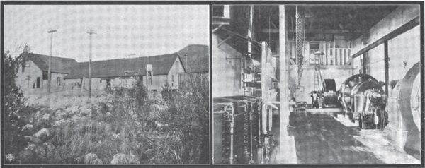
| |||
| The Santa Ana Plant From A Carbon Print |
Side-by-side the oldest American built polyphase apparatus works in perfect accord with the newest; fears forebodings, once all but overpowering, have gone the way of hobgoblins of childhood, and the first power transmission-born project of scarcely more then a decade ago, has grown and grown and grown from a slender infancy to the very perfection of corporate maturity, so that now, when it has but to ask for millions for extensions to receive them, it seems but fiction to think of a time but twelve short years ago when it proved to be all but impossible to secure the paltry sums represented in the cost of the plant that is the nucleus of the present mighty enterprise. If American prosperity has increased of late, the transmission development has advanced by a yet more rapid stride, and here and southern California the engineer may see it all, from its earliest stages to it's acme of perfection, and in seeing it he will be struck not only by its historical significance, but also by the unprecedented thoroughness of its hydraulic development and the marked originality, in equal thoroughness, which characterizes its every electrical feature. The Editor]
The system of The Edison Electric Company is a composite one, constituting, as it does, eight separate and distinct corporations, which, in process of time, have been gradually merged into the single concern of great magnitude, which bears the name of this article. If viewed from the standpoint of its interests in the city of Los Angeles the company originated in the comparatively small concern eventually known as the West Side Lighting Company, which, as time wore on and business increased, developed into the Edison Electric Company, that, in turn, became of great importance, especially after its absorption of the Southern California Power Company. Comparatively short periods of time wrought marked developments thereafter, and rapidly following the absorption of the Southern California Power Company by the Edison Electric Company came the acquisition in the sequence named of the Pasadena Electric Light and Power Company, the Santa Ana Gas and Electric Company, the Redlands Electric Light and Power Company, the California Power Company and the Mountain Power Company, all of which have been, within the last few months, as stated, merged into The Edison Electric Company.
THE REDLANDS BEGINNING.
And from a transmission standpoint, as stated, interest centers first about the plant of the Redlands Electric Light and Power Company, and then about the then-extraordinarily high voltage long distance lines of the southern California Power Company. It was in January, 1892, transmission development had begun to reach such a stage of progress as to inspire confidence in its ultimate commercial feasibility, and at the same time local conditions in and around Redlands were such as to make the proposition of transmitting the energy of the water power of Mill Creek to Redlands and extremely favorable one. It is certain, at events, that in the month named Messrs. George H. Crafts, George B. Ellis, F. G Ferand and H. H. Sinclair began to discuss the project with a thoroughness which has since become characteristic in the organization and development of electrical and transmission work in southern California. The most notable work of a similar nature to that proposed, and which was also under contract for building at that time, was the 10,000 volt, twenty eight mile and single phase incandescent lighting plant of the San Antonio Light and Power Company, familiarly known as the Pomona plant. This plant, which was, as stated, being installed, was built under the electrical engineering direction of Mr. A. W. Decker, who was also at that time in charge of the electrical work then being done in building the Mount Lowe Railway. Mr. Decker's qualifications and experience were such as to fit him pre-eminently for the position of electrical engineer of the new project at Redlands, and in June, 1892, he was employed in that capacity.
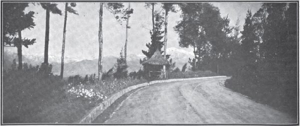
| |||
| A Beautiful View of Redlands and the San Bernardino Mountains is Had From Any Driveway on Smiley Heights. |
The Redlands electric Light and Power Company was incorporated in the spring of 1892 by residents of the town of Redlands in San Bernardino County, "for the purpose of supplying electric light and heat for both public and private use, power for manufacturing purposes and for the operation of street railroads and the city of Redlands in the country round about with a radius of ten miles," such power to be developed from a transmission plant that was to be built at the mouth of Mill Creek Canyon, some eight miles distant. At Redlands was a promising city with a population of 4500 people, and was lighted solely by oil and a few private gasoline plants. Coal was worth $11 a ton, and although the town was a small one, its prospects were exceedingly bright. It was further borne in mind by the promoters of the enterprise that the cities of Riverside and San Bernardino, each of a population of about 10,000, were comparatively nearby, that it is at a distance by rail of fifteen miles and nine miles respectively. These were then lighted by electricity generated from a water power developed from the irrigation canal which supplied Riverside, and the amount of power so obtained was a very limited quantity. The towns were then connected with each other and Redlands by a steam motor road, which it was hoped would eventually be changed to an electric railway system, to be operated by power developed at the Redlands plant.
It just interesting to note that of all the cities which have grown up in the western part of the United States in the ten years prior to the organization of the Redlands company, there have been none whose growth was more rapid than that of the city of Redlands prior to 1893, and a greater portion of the land included in the city limits of the town, which comprised about seventeen square miles, had never been turned by a plow, but early in 1887, began an influx of an active, well educated and well-to-do class of men who had and he six years which intervened built-up a town that is remarkable for its beauty of location, handsome some residences, well paved streets, substantial business blocks, and above all, for the superior quality of its oranges, which are equal, and by a great many considered the superior, in appearance and quality of those shipped from any other part of the United States. It possessed, unfortunately, a sad lack of inducements for manufacturing enterprises, and this, coupled with the reasons which have been named, led to the organization of the company which hoped to be able to furnish power to manufacturing industries at a price equivalent to that end localities where coal is $4.00 dollars a ton.
| |||
| The Original Redlands Plant As It is Today |
The first reality which gave assurance of the soundness of the ideas which underlaid the project, was the fact that they Union Ice Company, one of the largest handlers of ice in the western part of the United States properly entered into a contract with the Redlands Electric Light and Power Company to furnish electric power under a twenty-five year contract at a price that was so much cheaper than that which could be obtained elsewhere, that the ice company could afford to pay $2.00 per ton freight on 7000 tons of ice per year and still deliver it in Los Angeles at a rate of 50 cents per ton cheaper then it could be manufactured there under the most favorable circumstances. This contract proved to be the foundation upon which was built the business of the now historic Redlands plant.
Mr. Decker's investigation of the local conditions attending the plan soon resulted in a conviction that the transmission itself would have to be carried out along lines radically different from those which characterized not only the Pomona plant but also any other plant in America. The Redlands plant must be designed essentially as a power transmission plant, and accordingly Mr. Decker recommended the installation of a three-phase and transmission system having a rated capacity of 400 kilowatts. Preliminary plans and specifications for a plant of this kind were prepared by Mr. Decker and submitted to the General Electric Company, the Westinghouse Electric and Manufacturing Company, the Siemen & Halske Electric Company and the Electrical Engineering Company, of San Francisco. It took several months of active correspondence between Mr. Decker and the companies named before they would agree to submit bids on an installation of this kind, taking the ground generally that details were not yet sufficiently worked out to justify then them in bidding along such a plant, and recommending the use of such apparatus as was standard at that time. Bids were finally put in by the Westinghouse and General Electric companies and the Electrical Engineering Company, of San Francisco, the latter proposing a 5000-volt direct current generating and transmission system, with direct current motor operating single phase alternators in Redlands. The bid of the General Electric Company for two 250 kilowatt, 2400-volt, 600 revolution, three phase, Y-connected generators was accepted, and the execution of the contract formed the members of the famed Redlands plant. The bid of the Westinghouse company was for a two-phase system, which Mr. Decker would not entertain. This original plan, which is now known as Mill Creek No. 1 station of The Edison Electric Company, was driven by Pelton water wheels, and the transmission line consisted of two, three-phase circuits, each being of three No. 0, B. & S. gage, bare copper wires running to Redlands, a distance of seven and one-half miles by way of the pole line. Common deep groove, double petticoat, 2,200-volt glass insulators were used. The distribution at Redlands was tapped off the end of the land with out any substation, they delivered potential being 2300 volts. Both light and power where thus delivered, but the principal power service from this original plant consisted in the installation of a 120-kilowatt, three phase, synchronous motor for operating the manufacturing plant of the Union Ice Company. This motor also operates at 2300 volts, the distance from the station to the ice plant being practically four and one-half miles.
At the time of installation the switchboard was equipped with a General Electric Company with generator switches consisting of common 500-volt, triple-pole, double-throw switches, such as had been previously used in railway work, this being the best type of switch manufactured at the time. These switches could never be pulled on a load at the machine voltage, and as the busbars were and duplicate, when it became necessary to change over the station operators were compelled to break the filled circuit on the machine and shut down the plant. There is now on the system of Redlands company the first three-phase generators, the first synchronous motor and the first induction motor ever turned out for commercial use by the General Electric Company, and it is interesting to note that they are still in daily service as installed, with every indication that they will continue in their duties for years to come.
On another page there is published a biographical sketch of the life of A. W. Decker, the electrical engineer who drafted the electrical specifications under which the Redlands plant was built, and it is suggested that this sketch be read in order that an idea may be gained of the difficulties which were encountered at this early date in securing the installation of the three-phase plant, and that the work then performed by Mr. Decker and this conjunction may be given proper credit. At the same time it is interesting to review the memorandum of conditions and requirements of this plant as laid down by Mr. Decker prior to its installation. It is pointed out therein that the power of available under the then present developments at the minimum flow of Mill Creek measured 1000 miners inches, or 1200 cubic feet per minute, under an affective head of 295 feet, from which the total capacity of the power plant was estimated at 359 kilowatts. It was also shown that the total output of the plant made by an estimation of a pipe line, which was afterward checked, could be measured to twice that shown during the whole year, and that during six months of the year approximately three times this amount of power could be obtained.
| |||
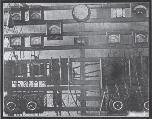
| The Original Switchboard in the Old Redlands Plant. Note the \"Growler\" Under the Clock |
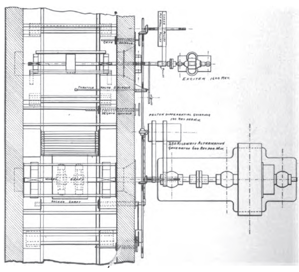
As already stated, there were first installed in the Redlands plant two 250-kilowatt three-phase generators, running at 600 revolutions per minute, and having a voltage of 2500. These machines were originally intended for belt driving, but, instead, they were installed with three bearings and direct-connected to Pelton water wheels, which were mounted in pairs directly connected through insulating couplings to the generators, and supplied with water from a receiver through a Y nozzle of the deflecting type. There were also two 7 1/2-kilowatt, 125-volt, compound wound exciters, that were separately driven by independent Pelton wheels, and which ran at a speed of 1600 revolutions per minute. The plant was governed by the old style differential governor, which was a familiar accompaniment of Pelton water wheel installations ten years or so ago. This mode of connection is shown in the accompanying line drawing, and its principle of action was that it was given a fixed speed so that the governor always tended to bring the nozzle to a position to correct the differences and speed between that of the generator and a source of constant speed. The unit which was selected for furnishing the constant speed was the exciter shaft, for the reason that exciter under normal conditions has a fixed load and practically a constant speed.
At the time of the writer's visit to the plant last winter the original switchboard had been dismantled and its parts stored, but in order that a faithful reproduction of the it in its original appearance might be given, the board was reassembled, and it has from this reassembled equipment that the accompanying halftone was made. It was, as the illustration shows, of the skeleton type, and there was mounted thereon a rheostat and triple-pole, double-throw switch, three ammeters and one volt meter for each machine, these instruments being of the Thomson-Houston type, and, as already stated, of the farm law of 500-volt railway apparatus them in use. The board was further equipped with two double-pole, double-throw line switches and three ammeters for each line, as well as being provided with double busbars.
Probably the greatest controversy that arose in the equipment of this plant, and after Mr. Decker had been forced by the manufacturing companies to recede from his demand for the direct generation of 5000 volts in a three-phase machine, was that due to the clause in his specifications which exacted the installation of generators of the three-phase type that would work in parallel. This procedure was declared by the chief engineer of the General Electric Company, before the Board of Directors of the Redlands Electric Light and Power Company, and the strongest terms, to be absolutely impossible of accomplishment, and it is interesting, indeed, to hear that relation of experiences that were encountered after the installation of the machines in the endeavor to parallel them. All kinds of expedients were resorted to in order to bring about some indication of the synchronism, and finally the General Electric Company produced a device, which became known as the growler, as being the best for accomplishing the result desired. This growler, which is illustrated herewith, was an attempt at an acoustic instrument, and in it the two separate phases which were to be synchronized were made to operate upon sheet iron diaphragms, placed several inches apart facing each other, the whole being enclosed in a sheet brass cylinder. At the center was cut a hole about an inch diameter, to which the station operator was to apply his ear, and it was expected that the operator could distinguish when the vibrations were in unison. In each of the upper corners of the base-board there was placed a sixteen-candle power incandescent lamp, being burned respectively from two of the three phases, but these lamps were used merely as pilots. The device failed, however, for, owing to the various harmonics generated by the machines in the station, it was impossible to tell with any degree of accuracy when the machines were in synchronism, and this condition led to the eventual abandonment of the growler, which, however, is carefully preserved in the Redlands plant for gets historical value.
EXTENSIONS OF THE REDLANDS SYSTEM.
In 1896 the business of the Redlands company had grown so that an extension became necessary, especially for the purpose of supplying power for pumping purposes. The transmission system was extended from Redlands to Colton and Riverside, and three 100-kilowatt Wagner transformers were installed in the powerhouse for raising the potential to 10,000 volts for the Riverside transmission.* At the same time that pipe line of the plant was expanded 3000 feet, which increased the head by eighty-six feet, making a total static head of 510 feet, or a pressure of 230 pounds per square inch. The total length of the pipe line as thus extended is 10,250 feet, most of which is of riveted steel 30 inches in diameter at the same time Pelton wheels of a latter type were installed, and this plant, as extended, constitutes the present Mill Creek No. 1 station of the Edison Electric Company.
 |
| The Pelton Wheels, Generators and Exciters Were Thus Arranged in the Original Redlands Plant |
Three years later, in 1899, the further growth of the business of the company had necessitated the building of the second station, now known as Mill Creek No. 2 station, which is so located that the water from its tail race is taken up directly by the intake of the pipe line and a Mill Creek No. 1 plant. The second plant contains to 250-kilowatt, revolving field, 11,500 volt, three-phase generators, running at 375 revolutions per minute. They were put in operation in November 1899, and though they have been in constant operation ever since, they have always given perfect satisfaction and have never caused one cent for repairs. It is in an extension to the building of Mill Creek No. 2 station that Mill Creek No. 3 plant is now being rapidly finished, and when this latter plant is running it will be noteworthy as being driven under a higher head of water than any other electric transmission and the world, namely, 1960 feet.
* THE JOURNAL, Volume IV, page 21, MAY, 1897.
Prior to this, however, or, to be exact, in December 1896, the people comprising the Redlands company organized a new corporation, known as the Southern California Power Company, which made service of the water rights of the Santa Ana Canyon, and having appropriated and perfected them, entered into contract, in the spring of 1897, for the apparatus which has since been installed as the Santa Ana Canyon-Los Angeles transmission plant. In April 1898, when the plant was partially completed, the entire property of the Southern California power company was sold to The Edison Electric Company, and the owners of the Southern California stock - Messrs. H. H. Sinclair and Henry Fisher - accepted in payment thereof stock of The Edison Electric Company. The Santa Ana Canyon plant was completed in December 1898, when water was first turned into the canal and since then it has never been turned out for a single instant. It should here be noted that Mr. O. H. Ensign was superintendent for the Southern California Power Company, and the electric installation, and the installation of the pressure pipe and water wheels, was made under his direct supervision. They hydraulic engineers were, first, Mr. M. L. Lumm, and, later, Mr. E. M Boggs, who remained in charge of the hydraulic work until its completion. The whole construction was under the general management of Mr. H. H. Sinclair, the plant costing approximately $625,000. To Mr. Sinclair and his associates there it is, then, due a lasting debt of gratitude by the engineering world for the part they took in pioneering the development of polyphase transmission and America.
THE LOS ANGELES BEGINNING.
On the other hand, if the origin of The Edison Electric Company be considered from the standpoint of its development in the city of Los Angeles, it must be regarded as beginning in the spring of 1895, when Mr. E. E. Peck applied to the Common Council of the city of Los Angeles for a franchise for the purpose of enabling himself and his associates to build and operate an electric lighting and power plant within the corporate limits. After no little delay the franchise asked for was finally advertised, but Mr. Peck was not the successful bidder. Later in the same year he entered a second application for an electric lighting and power franchise, but the Council would not even advertise it, and so, for the time, his efforts were thwarted. Nevertheless his perseverance never flagged, and during the latter part of the year named he succeeded in obtaining from the Board of Supervisors of Los Angeles County a franchise enabling him to build and operate an electric light and power plant in a small territory and immediately adjoining the city of Los Angeles on the southwest, throughout the district known at that time as the University and Rosedale tracts.
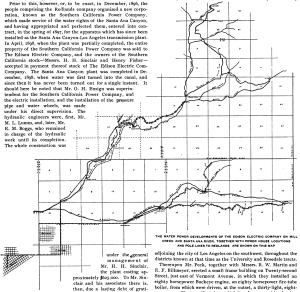 |
| The Water Power Developments of the Edison Electric Company on Mill Creek and Santa Ana River, Together With Power House Locations and Pole Lines to Redlands. Are Shown on This Map |
Thereupon Mr. Peck, together with Messrs. R. W. Martin and E. F. Billmeyer, erected a small frame building on Twenty-second Street, just east of Vermont Avenue, in which they installed and eighty horsepower Buckeye engine, an eighty horsepower fire-tube boiler, from which were driven, at the outset, a thirty-light, eighteen-ampere Western Electric arc lighting dynamo. After having installed and arc lighting circuit, they started in business in December 1895, with a load which reaches a "grand" total of five commercial arc lamps and three straight arcs, which latter were paid for by subscription by the residents thereabouts. Thus was made the Los Angeles beginning of the great system of the President Edison electric Company.
| |||
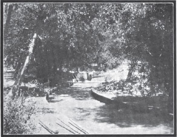
| This Flume Unites the Tail Races of Mill Creek Plants Nos. 2 and 3 With the Intake of Mill Creek Plant No. 1 |
But before starting this rather primitive electrical lighting plant, Mr. Peck was naturally looking for capital to aid him in its development, and as a result of his labors, Messrs. George H. Barker, W. R. Staats and W. S. Wright, of Pasadena, associated themselves with him, and in December 1895 a Fort Wayne 50-kilowatt 2000-volt alternator and some Fort Wayne transformers and Shallenberger meters of various sizes were ordered. In January 1896, Mr. E. Y. Ware came from Denver and joined in the enterprise, and under his direction the work of running a land to supply alternating current lighting service was begun. In the meantime Mr. Peck renewed his efforts to persuade the Council to advertise another franchise for sale, but without success. Nevertheless, the lines from the little plant were extended into the city by setting poles on private property and simply crossing the streets with the line wires, but the lines were harassed by competitors, and the city at last cut the wires. These were replaced as fast as cut, and they were finally let alone. Despairing of getting a franchise of their own for the city, the owners of the plant to finally bought an old franchise known as the Scott Franchise, in the spring of 1896. In order to fulfill its terms, they had but two weeks to get current into the City Hall, as the conditions of the Scott franchise were such that the municipal building had to be supplied with lighting current free of charge during the term of the franchise. To have secured the poles and built the long line necessary to reach the City Hall in that short time would have been a physical impossibility, and so, purely as an accommodation, permission was granted by the Los Angeles Traction Company which enable the plant to put its wires on the street railway poles of the Traction Company and thus it was that Mr. Peck and his associates were enabled to burn a cluster of lights in the City Hall on the night before the day on which the franchise would have lapsed had that not have been done. This was followed by controversy with the City Council as to whether it or the owners of the Scott franchise should prepare the City Hall for electric lights, but at last the Council finally decided to do it, which ended one important phase of the situation. Then the validity of the Scott franchise was attacked, and suit was brought to annul it, but this was finally settled in favor of the lighting plant, and so the controversy finally ended.
| |||
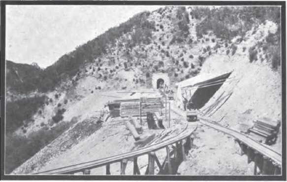
| The Portal of Tunnel No. 1 of Santa Ana Plant No. 1 |
To Messrs. Barker and Staats is due the credit for financing the project and its primary stages, and to Mr. W. S. Wright is due the credit for its legal work, both in the way of organization and in defending suits.
On June 5, 1896, the West Side Lighting Company was incorporated with a capitalization of $500,000, with George H. Barker, president; W. S. Wright, vice-president; W. R. Staats, secretary and Treasurer, and E. E. Peck and E. F. Billmeyer constituting the first board of directors. On July 6th, of the same year, Mr. Jason Evans succeeded Mr. Billmeyer, and on December 12th, Mr. J. H. Holmes succeeded Mr. Peck. On September 28th, also of 1896, a $300,000 bond issue was authorized, and the enterprise was launched into a solid, full-fledged corporate existence.
| |||
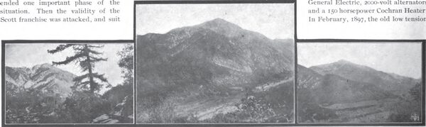
| Three Views of Mount San Bernardino and Mill Creek Canyon |
Soon after incorporating, a more central location for the plant was sought, and finally the old cable power house on the corner of Second and Boylston streets was purchased. The work of its transformation was rushed, and in December, 1896, the company began operations in its new location with two 90-horsepower Babcock 8 Wilcox boilers and a 60-horsepower Brownell open heater, one 150 horsepower Ideal Engine, and a 75-kilowatt, Fort Wayne, 2000-volt alternator. The old equipment was moved over from the frame building on Twenty-second Street, and an earnest campaign for business down town was begun. The business of the company increased so rapidly that in January 1897, two 200-horsepower Stirling boilers, one 175-horsepower Ideal Engine and one 120-kilowatt, General Electric, 2000-volt alternators were installed and a 150 horsepower Cochran Heater. In February, 1897, the old low tension arc dynamo was replaced by a Western Electric 9.6 ampere, 80-light arc machine and later a Wood 9.6-ampere, 80-light arc machine was added which were latter supplemented by a Brush 9.6-ampere, 125-light arc machine. In the fall of 1897 the company decided to go into the power business, and installed therefor, two 100-kilowatt, 550-volt, Westinghouse direct-current generators.
| |||
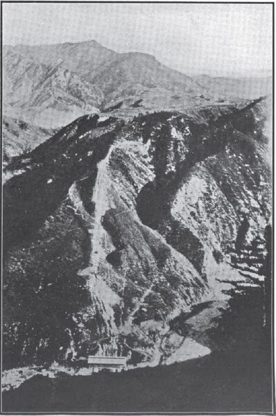
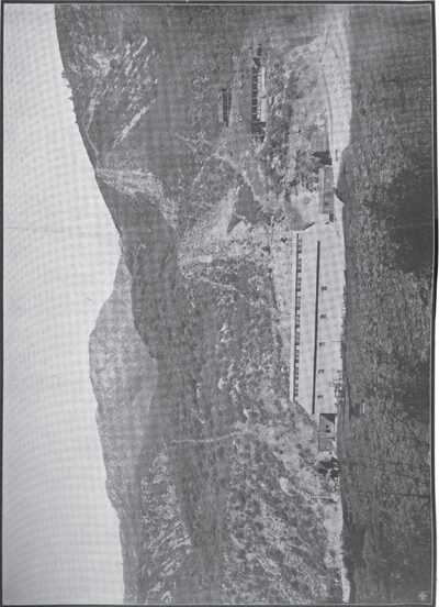
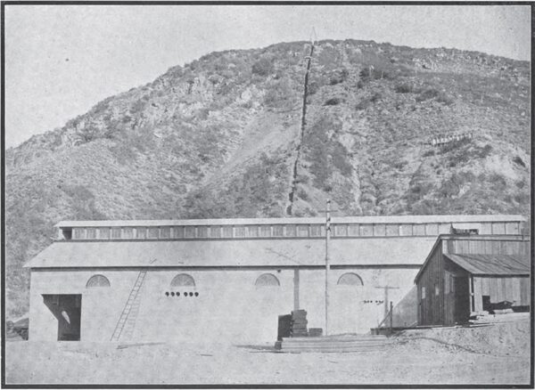
| A General View of Santa Ana Power Plant No. 1 |
In December, 1897 the West Side Lighting Company sold out to the Los Angeles Edison Electric Company, which had incorporated on July 9, 1894, with a capital of $500,000, it being necessary to assume that name in order to obtain the Edison licenses. The name was then changed to Edison Electric Company, which retained the old board of directors of the West Side Lighting Company, but others were taken on subsequently. It was about that time that Mr. John B. Miller, now president of The Edison Electric Company, entered the board, and was elected treasurer of the company, whereupon he at once became an important factor in financing the company to its present imposing position. Early 1898, another Stirling boiler was added to the steam equipment, as were also a 500-horsepower condenser and a 500-horsepower Day open heater. A 300-horsepower Ideal engine was purchased and utilized in driving a Westinghouse three-phase, 240-kilowatt, generator that had been supplied by the Southern California Power Company, with which The Edison Electric Company had contracted for power.
| |||
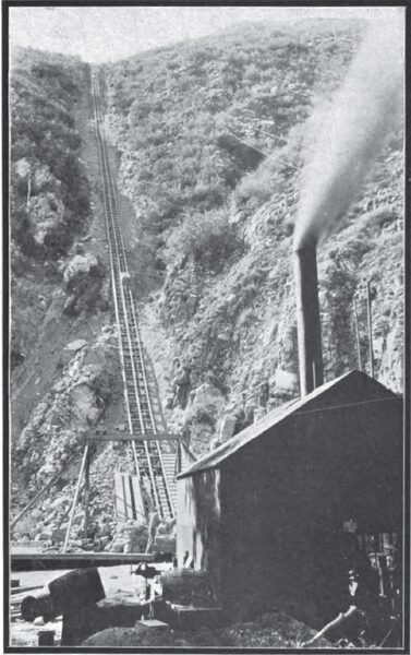
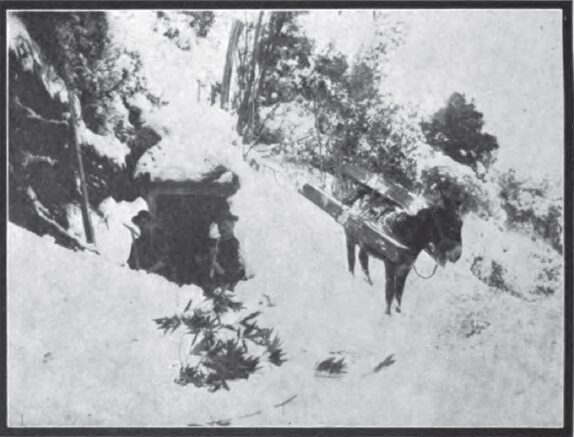
| Up This Tramway the Materials for the Pipe Line and Renstock of Santa Ana Plant No. 1 Were Taken |
Thus began the era of association between electric lighting and power interests of Los Angeles and power transmission interests of San Bernardino county, which eventuated in the consolidation of the two systems into a single enterprise which is second to none on the Pacific Coast in point of commercial and engineering importance.
| |||
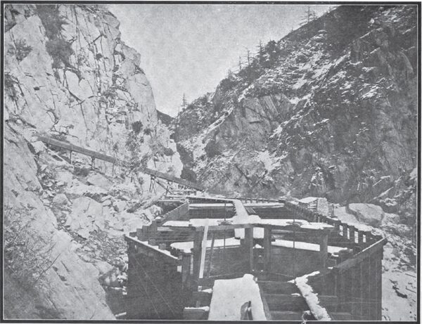
| The Construction of the Waterway of Santa Ana Plant No. 1 |
| |||
| A Winter Scene on the Line of the Canal of Santa Ana Plant No. 1 |
THROUGH MOUNTAINS AND ACROSS CANYONS.
It is a truly remarkable experience to go over the water courses of The Edison Electric Company in Santa Ana Canyon. Perhaps I might better have said through the water courses, for the tunnels are indeed the most interesting part of the whole work. The story of the great reservoir at Bear Valley, of its enormous storage capacity and of the Paradises which its waters have wrenched from arid wastes, is an oft-told tale* so I will not repeat it.
* For general conditions of the water supply of this section of southern California and data concerning its development for power purposes, see an article in The Engineering Magazine, Volume XIV, page 1011, by Mr. F. C. Finkle, March, 1898.
Less than three hours' drive takes one-figuratively transports one-from the beauties of Redlands to the grandeurs of the Santa Ana Canyon. First, by bowered houses, then past orange groves that fill the air with Eden and on we drive across and up the great river bed of the Santa Ana into its rugged canyon. The altitude and the deep shallows in the canyon make driving chilly it is winter anyway but "a drink that will cheer" is promised us soon, and when time has given a sufficient whet to our longings, we reach the stopping place where "hot drinks" are served, fresh from a bubbling spring of boiling mineral water. Better toddy never was than this, so they say, and on we go past the power house and up to the intake of the canal. A few rods above is the confluence of Bear Creek and Santa Ana River, then comes the diversion with its gates and sandbox and directly the stream is swallowed by the gaping portal of Tunnel No. 1. Then we returned to the road and went back down the canyon for a half mile or so, and a short climb up the base of the mountain brought us again to the canal at the sand box, between the mouths of Tunnels Nos. 3 and 4. Here our boat awaited us, and, nearby, smoking restful corncobs and wearing great gum boots that reached the hips, were the three men who had spent the previous four hours in pushing this self-same boat up against the waters that rush on their way to the power house. And our party was to float down in that boat, like the rich in their chaises, while these men were to walk back, by gracious, but such is life!
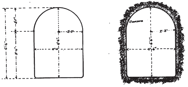 |
| Sections of Tunnels Santa Ana Plant No. 1 |
Plash! Plash! in measured time sounded the buckets of the paddle wheel that raked leaves from off the screen in the sand box, and to the tune of its slow beating one by one we backed down through a narrow opening into the boat hidden partly within the tunnel.
"Like crawfish, backing under a sheltering rock" quoth I.
"Like lobsters, attempting to escape being boiled alive" quoth my wife, who abhors tunnels and high bridges and uncanny adventures.
So we piled in, all five of us (there was room in the boat for as many more), and began a ride that was, to use the vernacular, the "very oddest ever." A man standing in the bow had a lantern and as the boat would approach the sides of the tunnel he would push it off to keep from scraping. We first-class passengers, seated on boards softened by a single spread of gunny sacking, and presumably entitled to all the priveleges [sic] privileges of the saloon of the ship, soon began to feel the cold, and there followed a mutinous outcry against a saloon which had no bar.
Then up spoke the worthy captain, "The bar's all right; you'll find it in due season."
On we drifted, ever onward toward that knothole of light perhaps a thousand feet down the tunnel through a seemingly interminable way of inky darkness.
"We'll have to be pretty long drawn out to escape through that hole," said sonic one. The current was rapidly becoming swifter and the wierd [sic] weird silence of the tunnel was giving way to the babble of rushing waters.
Then: "Here's your bar," said the captain. "Line up."
The boat scraped along the bottom for a time, then skewed from side to side and finally, with a rasping grunt, stopped stock still. But it was only for a moment, for the water, backing up at the stern, gave it a mighty shove that upset the composure and balance of we uninitiateds [sic] uninitiated and sent our craft merrily out beyond into the deep water of the tunnel.
"Is that the bar you promised us?" demanded one.
"You 'line up' your friends by leaving 'em lyin' down," observed another.
"What shall we do with him, fellow citizens?" demanded a third.
And the outraged passengers, like the people of ancient Rome, roared vengeance by hanging, killing, drowning and otherwise, until the captain promised to be good and "square matters" later.
| |||
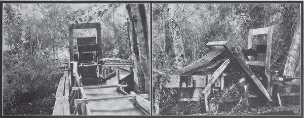
| Screen Method of Removing Leaves and Debris From the Santa Ana Flume |
As on we went the knothole grew larger, and as the light and temperature increased, our senses mellowed to beauties of the scene through which we were passing. It chanced that the rays of the sun were falling squarely into the mouth of the tunnel from which we were about to emerge. The cement lining of the tunnel, faithful to its trust, made the sides and roof as dry as tinder, and tiny spiders, seizing the opportunity presented in the dry location and the prospect of rich harvests, had frescoed the walls with thousands of silken webs upon which the sunlight, reflected from the water below, shone in matchless iridescence.
| |||
| \"Plash! Plash! in Measured Time Sounded the Buckets of the Paddle Wheels That Raked the Leaves From Off the Flume\" |
We were silent now, and joking could not be, and on we leisured, from darkness through glories into the warmth of the God's blessed-sunlight which marked our delivery to the flame. Didn't the warm air feel good, though, and wasn't the balm of the mountain foliage delicious, even if we got but glints of them through the timbering of the flame as we still drifted onward.
Then some one said that we had come literally as from night to day. Another thought it was like turning from the chrysalis to the butterfly. Then others indulged in such cheap talk as anent the egg and the chicken, and the jackass that was born down in the coal mine, butt which at last was taken up above ground. And when each was asked if he felt like the poor Jack, such is the contradiction of human nature that not one would answer aye.
| |||
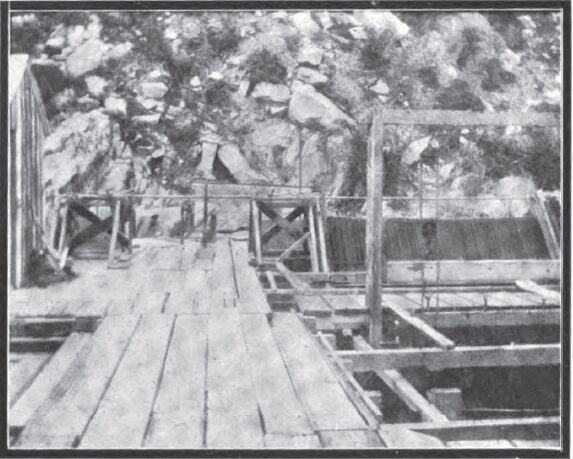
| Two-Way Sand Box in Santa Ana Canyon Below the Intake of Santa Ana Plant No. 1 |
Thus were scenes repeated as we journeyed down that wondrous waterway. Some tunnels were short, some were long and one of them - the longest of all - stretched out to a length of over 2000 feet, and in its center we were some 1500 feet beneath the surface of the mountain above. The further down we went the higher grew the elevation of the flumes above the river, until at last, in looking over the sides, it was dizzying to contemplate the more than 700 feet of abyss that yawned invitingly beneath us. In all, there are eighteen tunnels and sixteen flumes in this waterway, which aggregates a length of 14,384 feet or practically two and three-quarters miles, and the time consumed in making the trip down it by boat was twenty minutes.
We did not go through the final tunnel, for the water was backed up at the penstock that the tunnel was filled to its roof and indeed it was very "low bridge" in the next to the last tunnel which we traversed. Next came an arduous climb up and around the mountain on which the pipe line was placed, then to an equally arduous descent down the pipe line to the power house where, thanks to a thoughtful host and hostess, dinner was awaiting our arrival. And you may be assured that after we had finished there was no dinner left to "warm up" for supper.
Topographically, Mill Creek Canyon differs radically from, Santa Ana Canyon, for while the latter below the junction of the Santa Ana River and Bear Creek is virtually a barren ragged mountain gorge, through which the waters rush almost torrentially. Mill Creek is a stream of goodly size and of very even temperament in its flow. That it should be so becomes evident to any one who has driven up along its beautiful course, for here instead of bleak rock, rock, rock everywhere, as exists in Santa Ana Canyon, there are alders and cottonwoods and hazels and shrubbery galore, which 'neath the foot ferns and mosses thrive luxuriously. It is a most beautiful canyon, wherein through the long summer months campers find a matchless Mecca. Its soil, deep and absorbent, stores up the winter rains and the melting snows of spring to give them back through the summer and autumn months, and thus it is that Mill Creek has been endowed by Nature with its perennial flow. To the north, the grizzled side of old Mount San Bernardino rears to its mighty eminence, and, like the southern sides of all mountains in the southern part of the State of California, it is Covered only with rock that is bare except for the chapparel [sic] chaparral and greasewood that grows here and there. But across the canyon on the northerly exposure all is different, for there vegetation is shielded from the blanching rays of the sun and it thrives in utmost glory, from the tenderest maiden hair and lichen to the sturdiest oak and pin.
HYDRAULIC CONDUIT, SANTA ANA CANYON PLANT NO. 1.
The hydraulic conduit supplying water to power plant No. 1 of The Edison Electric Company, in Santa Ana Canyon, which was completed in the year 1898, begins at the junction of Bear Creek and Santa Ana River. The diversion of the water is made by means of two branch flumes, one carrying the waters of Bear Creek, and the other one, those of the Santa Ana River, to the junction where they are delivered into tunnel No. 1 at the head of the conduit. The water is delivered into these flumes by means of dams placed across the two channels. It is the purpose of the company to construct a dam across the canyon immediately below the junction of the two streams which will raise the level of the water sufficiently to do away with the two flumes. When this dam is constructed the water will be raised by means of it to a level which will deliver it directly into tunnel No. 1, hence it will flow as at present down the canal.
| |||
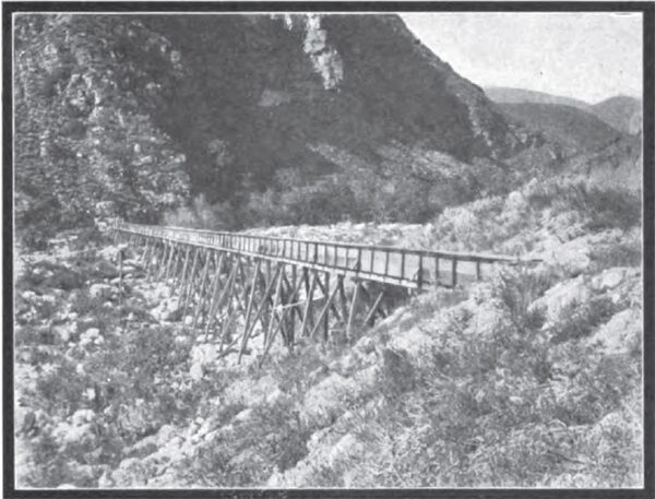
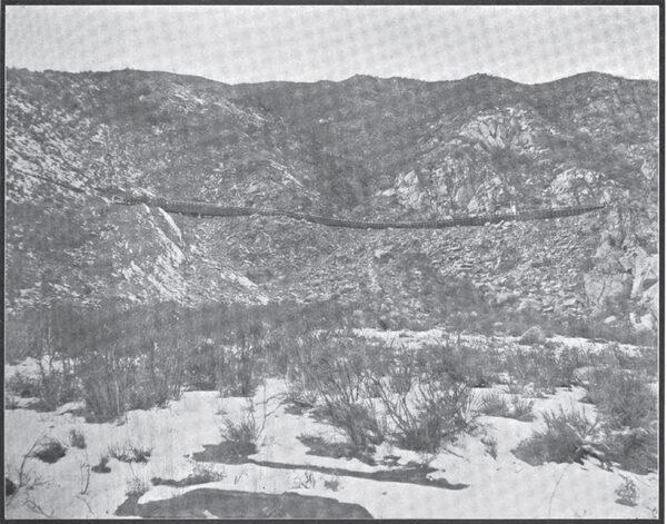
| The Longest Flume on the Waterway of Santa Ana Plant No. 1 |
The line of the conduit consists of eighteen tunnels driven through the various spurs of the mountain side, extending from the junction of Bear Creek and Santa Ana River to the head of the pressure pipe, and of a number of flumes spanning the canyons between the various tunnels. The length of the various tunnels on this conduit are as follows:
Tunnel No. 1, 220 feet; tunnel No. 2, 460 feet; tunnel No. 3, 700 feet; tunnel No. 4, 530 feet; tunnels Nos. 5 and 6, combined, 900 feet; tunnel No. 7, 900 feet; tunnel No. 8, 2070 feet; tunnel No. 9, 730 feet; tunnel No. 10, 850 feet; tunnel No. 11, 700 feet; tunnel No. 12, 840 feet; tunnel No. 13, 210 feet; tunnel No. 14, 540 feet; tunnel No. 15, 220 feet; tunnel No. 16, 780 feet; tunnel No. 17, 560 feet; tunnel No. 18, 830 feet; total, 12,040 feet.
All of these tunnels are lined with concrete throughout so as to give a net width of four and one-half feet and a net height of six and one-half feet. The method of construction is shown in the drawing of tunnel sections appearing on page 17, and in the illustration of the portal of tunnel No. 1 appearing on page 14 of this issue. The carrying capacity of these tunnels is 120 second-feet of water, which will generate at the power station 6000 horsepower. The tunnels are all connected by means of flumes spanning the ravines. The carrying capacity of the flumes is the same as that of the tunnels - 120 second-feet of water.
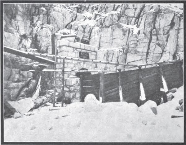
The conduit has been constantly in use since the latter part of the year 1898, and it has never been found necessary to turn the water out for the purpose of making repairs to the work. After the water is admitted at the head of the conduit it is passed through a sandbox or settling basin where the sediment is allowed to precipitate before the water is carried on to the power plant. This sandbox consists of two parallel hoppers with sluice gates in the bottom through which the accumulated silt can be expelled. The water is passed through one hopper while the other is being emptied, thus causing no interruption of the flow of water while the sand sluicing is in progress.
| |||
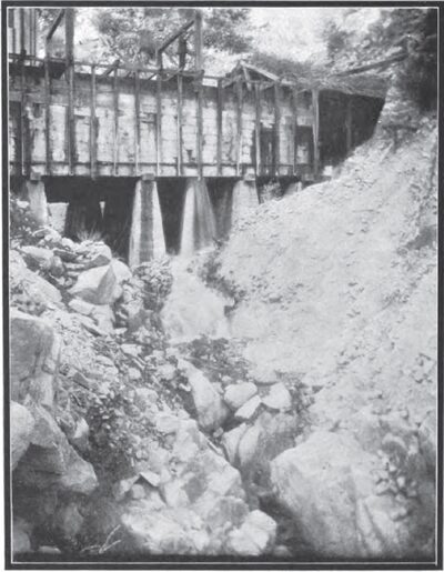
| Sand is Flushed Out Through Holes in the Bottom of the Sand Box |
Above the intake of this conduit is a tributary watershed of 172 square miles, raning in elevation above sea from 3500 to 12,000 feet. On the upper portion of Bear Creek is a storage reservoir regulating the discharge from fifty-four square miles of this watershed, storing the winter flood and permitting the water to be discharged during the dry season when most needed. The Bear Valley reservoir has a dam fifty-four feet in height and a storage capacity in the basin behind this dam of 9,778,440,000 gallons. All the water flowing from this reservoir must pass down Bear Creek to the intake of the Santa Ana conduit and power plant No. 1, whence it is diverted and carried down to the power house combined with the flow of the Santa Ana River.
| |||
| From the Commencement to the Completion of Santa Ana Power House No. 1 |
Below the intake tunnel, where the water is run through the sand box, there is a large grizzly having a cross section of thirty feet by seven feet, and over which there travels a rake every quarter of a minute, this rake being driven by a paddle wheel placed in the main canal. The arrangement has proven so effective in heavy storms which occur in the beginning of the winter season, causing the water to bring down quantities of small debris, that, although it has sometimes happened that the headworks men could not give the sand much attention for seven hours, they have at the end of that time found the penstock to be perfectly clear of leaves and driftwood, and as a result the plant has never suffered interruption. This sandbox peculiar in that it consists simply of two large rectangular reservoirs, the bottom of which are divided into several small compartments which have a depth of two feet. The sand box has a grade of two feet in fifty, and at the lower end of the compartments named there is a plug valve eight inches in diameter, which is provided with a stem that runs up through the water to the board walk above. This valve is lifted by a small block and tackle, which opens the hole in the bottom of the compartment, and as the water can be turned into each compartment, it is an easy matter to clear the box of sand in a very few minutes with a small amount of water. So effective and simple is this arrangement in operation that no trouble whatever has been caused by sand, which, however, would not otherwise be a great source of trouble except during a few weeks of winter storms when the canyon stream becomes torrential.
THE PIPE LINE IN SANTA ANA CANYON.
It is a very precipitous mountain which overtops the location of the power plant of The Edison Electric Company in Santa Ana Canyon, and, as is the case will all high head power plants, the station is situated at the base of the mountain, which, in the present instance, gives a fall for the pressure pipe of 728 feet, the water being conveyed in a thirty-inch steel riveted pipe which has a length of 2210 feet. This pipe begins at the end of tunnel No. 18, which has a length of 1260 feet, and in which the water is backed up to a depth of six feet. The pipe line at the penstock is of three-sixteenths-inch steel, and terminates at the power house with a thickness of nine-sixteenths of an inch. It is double-lap riveted in the longitudinal seams throughout, and single riveted in the round seams, and is protected by thoroughly dipping in a mixture of asphaltum and crude oil. Moreover, the pipe line is buried throughout at an average depth of seven feet firm ground, which is of such solid nature that no other anchoring further than the weight of the earth upon it is necessary.
| |||
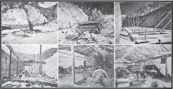
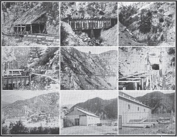
| A Series of Views of Interesting Features of Santa Ana Plant No. 1 |
It is laid in almost a straight line; in fact, it contains no angle greater than ten degrees. As to the method of laying this pipe line, it was started from a point about seventy-five feet from the power house and laid up the hill. The last joint was connected into the power house by riveting in a collar on a warm day, and, as much as all the pipe above had been buried, there was no chance for the pipe to move down hill and thus put a strain on the power house fittings. The second pipe line, parallel to the first one, is still to be installed, and preparations have been made in which it will enter the receiver. The receiver is the same diameter as the pipe now installed, and sets at right angles to it, and water for one unit is taken directly from in front of the pipe line, with one unit on either side. Although this arrangement necessitates making a right angle at the tee, practically no drop in pressure results from this angle. In fact, the drop in pressure is by test only a pound and a half. It will be practicable to shut off the valve on either pipe line and empty it for repairs or inspection without interruption to the plant. A valve will also be placed in the receiver, dividing it into two halves, each fed by one pressure pipe, and so arranged that water for the exciter wheels can be taken from either half. At the head of the pipe line there has been placed a gate, consisting of a rectangular piece of boiler plate working in brass slides, and by means of which the water can be shut off from the pipe line. This gate is under electrical control and is operated by means of a push button placed in the power house. Its valves act by means of oil upon a ram, pressure being given to the oil by reason of a pipe line running to a storage tank filled with oil placed at an elevation of about 127 feet up the mountain side. While it would have been possible to have used water for this purpose during much of the time, it was deemed advisable to use oil, because it will neither freeze in cold weather nor cause either the cylinder or piston to rust.
THE HYDRAULIC FEATURES OF MILL CREEK NO. 1 PLANT.
The hydraulic features of Mill Creek Plant No. 1 were installed under the direction of W. C. Butler of Redlands, hydraulic engineer to the Redlands company, and, as first installed, the wheels were supplied with water at a head of 377 feet, but in 1896 the pipe line was extended a distance of 3000 feet up the canyon, which increased the head to 530 feet, and at the same time the Pelton wheels and nozzles were changed. The pipe line then consisted of 10,250 feet of riveted steel pipe, beginning with No. 12 gauge at the upper end and terminating in 5/16 at the receiver. The pipe line was thirty inches in diameter, while the receiver had a diameter of forty-eight inches, and upon it the nozzles were riveted. The water wheels were arranged underneath the receiver, with the wheel shaft set at right angles to it, and, the shaft being extended through the wall into the power house, the nozzles discharged into a common tail-race running longitudinally just outside the wall of the power house. At the time these alterations were effected a third machine of similar capacity was installed, and its mode of installation was the counterpart of that of the two previous machines, with the exception that it was given two bearings.
| |||
| Santa Ana Power House No. 1, Showing Pipe Line Trench and Reservoir for the Lombard Governors |
THE HYDRAULIC FEATURES OF MILL CREEK NO. 2 PLANT.
It was in 1898 that the load which had been thrust upon the original Redlands plant became so heavy as to make it imperative that further power should be developed, and fortunately the location of Mill Creek was such that all the water which ran through plant No. 1 was susceptible to prior use by diverting it further up the canyon and applying it at a new location, known as No. 2 plant, which could be situated so that the water from its tail-race would be immediately taken up by the intake of the pipe line of No. 1 plant. In line with this policy the construction of Mill Creek plant No. 2 was begun on the 24th day of October, 1898, and it was completed upon the 1st day of September, 1899, having been carried on continuously between those dates.
The map on page 13 gives not only the location of the power plants of The Edison Electric Company in San Bernardino County, but also shows the routes of Santa Ana River and Mill Creek, as well as the locations of their waterways and diversions. The water from Mill Creek No. 2 plant is diverted by means of a tunnel about 400 feet in length, the upper end of which under the bed of Mill Creek at a depth of eighteen feet below surface. This tunnel collects the underflow of the stream intercepting it as it passes through the voids in the gravel and comprising the channel. The surface flow is diverted in a tunnel through a shaft communicating with the level in the tunnel and located near the bank of the stream. This is lined with concrete and has a grating of steel T-rails in top adjoining the stream, through which the water enters it, and by means of this grating all debris and rocks are excluded from the shaft and tunnel. There is also a gate for regulating the amount of water entering the shaft, placed just outside of the grating. A concrete dam three feet above the level of the channel deflects the water into the shaft. There is a sluice gate in this dam, by the opening of which the water passes down stream instead of into the tunnel. The tunnel is partly in solid rock and partly in boulders and gravel, being timbered concrete lined with the latter.
There are twenty-two flumes along the line of power plant No. 2. These are for crossing ravines and flats lying below the grade line and passing along the sides of certain rocky and precipitous cliffs. They are each from twenty-two to 400 feet in length and usually consist of sixteen-foot spans. In some cases where footings for the trestles could not be found that close together the spans are made thirty-two feet long and supported by hog-chain trusses. The dimensions of flume are thirty-six inches wide by twenty-six inches deep, the flume box being constructed of one-and-one-half-inch clear surfaced redwood, placed in position longitudinally to the flow of the water. The trestle caps, stringers and yokes are all of clear Oregon pine, and footings for trestles are constructed of cement concrete. Flumes in exposed places are heavily covered with planks and timbered from two to six inches in thickness. Such covering is for the purpose of protecting the flume against rolling boulders and landslides.
Flume No. 1 is located between the intake tunnel and the sand box. All the other flumes are in the conduit below the sand box, being distributed throughout the entire line. The most notable and picturesque of these flumes is the one known as Sheep Cliff flume, which is constructed along the side of a nearly vertical cliff. The total combined length of all the flumes on power plant No. 2 is three-fourths of a mile.
| |||
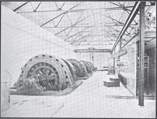
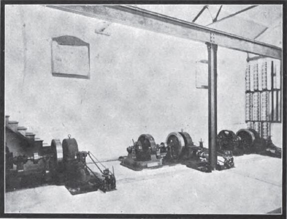
| The Interior of Santa Ana Power Plant No. 1 |
The remaining portion of the gravity conduit not in flume consists of Portland cement concrete pipe having an internal diameter of twenty-two inches. The length of such concrete pipe is two and one-quarter miles. The pipe was made in two-foot sections with a thickness of shell of two inches. The material used was the natural gravel and sand taken from Mill Creek wash, screened through one-and-three-quarter-inch mesh, three parts, and Portland cement, manufactured at Colton, Cal., one part, by measure. After the materials were properly wet, and thoroughly mixed, the pipe was made in forms such as are ordinarily used for the purpose. When time for curing had elapsed, the pipe sections were hoisted, two for each trip, on a standing line cable extending from the bottom of Mill Creek Canyon to the trench grade on the mountain side above. From the platform at the upper end of hoists the pipes were rolled in the trench to the place where they were used. Joints used in laying the pipe were of the Ogee type, with heavy cement collars on the outside and smooth finish inside.
At the intake of the pipe, below the sand box and at the lower end of each flume, taper pipes from twenty-six to twenty-two inches inside diameter were used for the purpose of overcoming any possible loss of carrying capacity due to entry head. The trenches were laid out in such a manner as to create no curve having a lesser radius than eighteen feet, while nearly all curves are of more than fifty feet radius.
The grade of the gravity conduit, both the flumes and pipe, is two-tenths of a foot per 100 feet, and the result of the construction of the flumes and pipes above described on this grade was to produce a conduit having a capacity of ten second-feet of water.
The maintenance of the twenty-two-inch pipe is made easy by manholes along the line, which are located at intervals of 500 feet. The pipe, after being laid, was covered with from two to three feet in depth of soil and rock, which protects it from laud- slides and rolling boulders.
After passing through the intake tunnel and flume No. I the water enters the sand box or settling basin of concrete. This is twenty-two feet wide by fifty feet long and is divided into five compartments by means of concrete cross walls. The depth of the sand box is five feet along the upper side and nine feet along the lower. In addition to having a slope of four feet in twenty- two thus created, the bottom of each chamber is V-shaped, so that sand collected can easily be expelled by sluicing through the gate at the lower end of the chamber. A flume passing along the upper side makes it possible to deliver the water into any one of the five chambers, from which it can pass on from one compartment to the other through wide crested weirs, until it finally reaches the pipe line. The large cross section occupied by the water while passing through the sand box reduces its velocity so that silt carried in suspension will be deposited before it reaches the pipe line.
There were originally five tunnels constructed on the line of No. 2 power plant. These are of the following lengths: Tunnel No. I, 400 feet; tunnel No. 2, 450 feet; tunnel No. 3, 450 feet; tunnel No. 4, 570 feet; tunnel No. 5, 140 feet.
Concrete pipes, the same as laid in the trench, are laid through all the tunnels. Since the construction of the plant another tunnel, located between tunnels Nos. 3 and 4, has been added. This takes the place of flume No. 18, which was slightly damaged in a storm, thus deeming it advisable to drive a tunnel behind the canyon spanned by this flume. The length of this new tunnel is 173 feet.
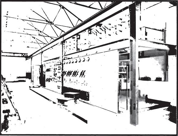 |
| Generator and High Tension Switchboards in Santa Ana Power Plant No. 1 |
At the end of the gravity conduit a forebay, twenty feet by seventeen feet, inside measurement, and from five to ten feet deep, has been constructed of concrete masonry. The purpose of this is two-fold, namely, to allow the water to settle before entering the pressure pipe, so that silt which may have been washed into the conduit, through possible breaks, will be deposited, and so created a penstock for submerging the inlet of the pressure pipe. The very decided slope of the forebay bottom renders it extremely easy to expel accumulated sediment through the waste gate placed in the lowest corner of the structure.
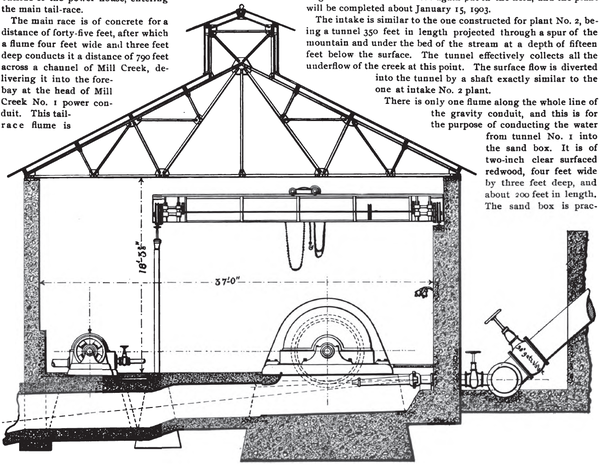 |
| End Section of Santa Ana Power House No. 1 |
The length of pressure pipe from forebay to power house is 1411 feet, giving a fall of 627 feet between the two points. This pipe is eighteen inches inside diameter, and is manufactured from steel plate, No. 14 to No. o, B. W. G. The pipe is made with double-riveted longitudinal seams and single-riveted round seams. It is double-dipped in asphaltum to preserve it against rusting. The whole line is laid in a trench from three to six feet deep, and carefully back-filled with earth and rock.
Heavy anchors of concrete are placed, extending all around the pipe, at five different points on the line. These are dovetailed into the solid rock in the sides and bottom of the pipe trench, and will prevent movement of the pipe line under all possible conditions. At the end of the main pressure pipe there is a large cast steel Y, by means of which the line is branched into three pipes, two of which are thirteen inches in diameter and conduct water to the two generators operated from this pipe line, while the third is six inches in diameter, being used for supplying water to the two exciters. Since the curves made in branching the pipe are all of long radius, there are no losses of head due to elbows and angles. The pipe line is well equipped with blow-offs, air valves and pressure gauges. There is also a stand-pipe for the escape of air bubbles located at a point twenty feet lower than the forebay, an air chamber for counteracting water hammer, located near the power house, and two eighteen-inch gate valves, one at each end of the main pipe line. The factor of safety for everything entering into the construction of the pipe line ranges from five to six, and its operation for more than two and one-half years has shown it to be perfect in every respect.
For the overflow of the forebay a waste flume, constructed of two-inch clear surfaced redwood, and 1200 feet in length, extends down the slope of the mountain to Mill Creek. This waste flume is for carrying any portion, or all, of the water flowing in the gravity conduit back to Mill Creek stream when it is not passing through the pressure pipe. It has a capacity sufficient to carry all of the water flowing in the gravity conduit, and it is securely anchored to the bedrock and soil of the mountain.
The water, after passing through the water wheels, or when deflected from there, passes out through a tunnel from each wheel pit, and below the power house floor. In these tunnels, and immediately beyond the line of the generators, are placed upper and lower curved deflector plates. The stream, when either partly or wholly deflected, strikes the upper plate, which is anchored in the arch of the tail-race tunnel, and is turned down, striking the other plate in the tunnel floor. The curve of the lower plate is such as to again direct the water along the floor of the tail-race, in which manner it passes for a distance of thirty feet beyond the outside of the power house, entering the main tail-race.
The main race is of concrete for a distance of forty-five feet, after which a flume four feet wide and three feet deep conducts it a distance of 790 feet across a channel of Mill Creek, delivering it into the fore-bay at the head of Mill Creek No. 1 power conduit. This tail-race flume is constructed of clear redwood, from one and one-half to two inches in thickness, on a trestle work from four to sixteen feet in height. The arrangement of the tail-races has proven entirely satisfactory. When the stream is wholly deflected the force of the jet is completely neutralized by the two deflectors, causing the water to pass through the portion of the tail-races beyond at an ordinary velocity. The wear of the plates up to the present time has been very slight; but should it ever become necessary, they can readily be replaced by new ones, since they are bolted down on the concrete and not embedded in it.
The power house, which was thirty-seven and one-half by forty feet, is built entirely of concrete masonry and steel, and is equipped with a fifteen-ton traveling crane. The walls and floor of the building are of concrete and the roof is a steel truss of flat and angle bars covered with galvanized corrugated iron.
The designs and superintendence of construction for the above were by F. C. Finkle, during 1898 and 1899, as chief engineer of the Redlands Electric Light and Power Company, which built the plant. The water wheels were designed by the Pelton Water Wheel Company, and the electrical equipment by the General Electric Company, but were installed under the superintendence of H. H. Sinclair, president, and F. C. Finkle, chief engineer, of the Redlands Electric Light and Power Company.
THE HYDRAULIC FEATURES OF MILL CREEK NO. 3 PLANT.
There was one mouth's active construction on this power plant during July, 1899. After this and until July 1, 1901, work was carried on with a small force driving tunnels. On July 1, 1901, a large construction force was again put in the field, and the plant will be completed about January 15, 1903.
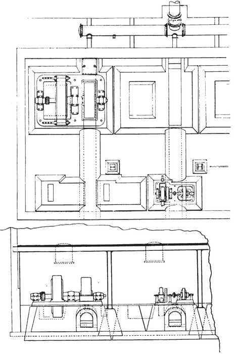 |
| Plan and Elevation of A Generator Section of Santa Ana Plant No. 1 |
The intake is similar to the one constructed for plant No. 2, being a tunnel 350 feet in length projected through a spur of the mountain and under the bed of the stream at a depth of fifteen feet below the surface. The tunnel effectively collects all the underflow of the creek at this point. The surface flow is diverted into the tunnel by a shaft exactly similar to the one at intake No. 2 plant.
| |||
| The Exciter Section Santa Ana Plant No. 1 |
There is only one flume along the whole line of the gravity conduit, and this is for the purpose of conducting the water from tunnel No. I into the sand box. It is of two-inch clear surfaced redwood, four feet wide by three feet deep, and about 200 feet in length. The sand box is practically 100 feet long by fifty feet wide, and built according to the plan of sand box for plant No. 2, with the following exceptions: There are eight chambers twelve and one-half feet wide by fifty feet long; the slope in each of these towards the gate is four feet in fifty, and all of the dividing walls between the chambers is three feet below the water surface in the sand box, except the middle wall, which is higher than the water surface, and allows the water to pass through a gate instead of over the wall.
| |||
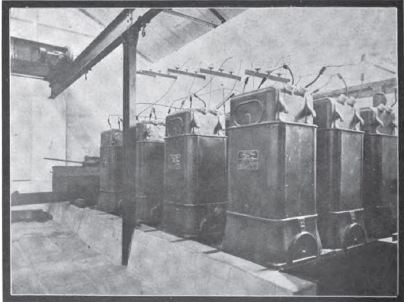
| The Transformer Section Santa Ana Plant No. 1 |
While the precautions which have been taken to clear the water which will be applied to the water wheels of Mill Creek plant No. 3 are unusually thorough, it should be remembered that the high head at which these wheels operate make it necessary that the water should be as free from grit and sediment as is possible.
There are five places along the line of the gravity conduit requiring inverted siphons. These are described as follows:
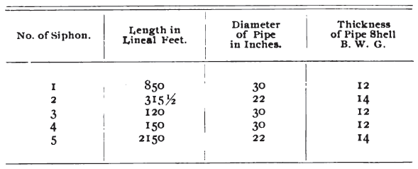 |
These siphons are equipped with blow-offs, air valves and bell-month taper inlets. The profile of the line gives such au hydraulic head on each siphon as to make the carrying capacity of each twenty second-feet of water, regardless of the fact that they vary in diameter. All the siphon pipes are laid in covered trenches, with the top of pipe three feet below surface of ground. There will be about 25,000 lineal feet of concrete pipe of thirty-one inches inside diameter. The shell of this pipe is three inches thick. It is made of wash sand and gravel, screened through two-and-one-half-inch mesh, two and one-half parts, to Portland cement one part, by measure. The mortar is well mixed, sprinkled to make it wet, and tamped in forms such as are ordinarily used for making cement pipe. The pipe is made in two-foot sections and laid with heavy cement collars outside for joints, and plastered smoothly inside. The trench is back-filled to cover the pipe at least three feet everywhere. The pipe is laid through all of the tunnels, as well as along the open country between them, except where siphons are constructed. The grade of the gravity conduit is two-tenths of a foot per 100 feet, which will give a carrying capacity of twenty cubic feet per second.
There are nineteen tunnels on line of power plant No. 3 in Mill Creek. They are excavated four feet wide by six feet high in the clear. The length of each of these tunnels is given in the following table:
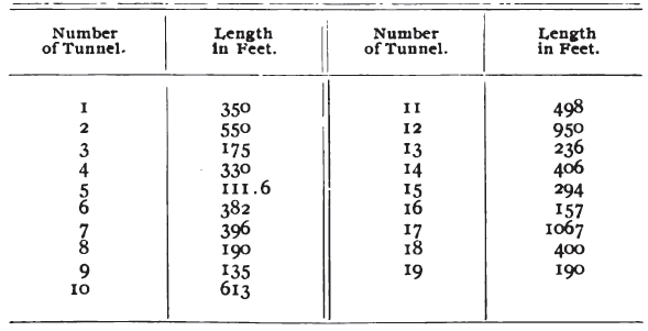 |
At the end of the gravity conduit is located a forebay sufficient to hold ten second-feet of water, continuous flow, for six hours. The purpose of this structure is to store the surplus water at times when the load on the plant is light and make it available on the peak load, extending over about six hours each day. The forebay is constructed by throwing an earthen dam twenty feet long on the bottom, 166 feet long on the top, and thirty feet high across a ravine at the head of the pressure pipe. The dam is rendered impervious by paving its up-stream slope with cement, and all weak places in the bottom and sides of the reservoir will also be similarly paved. The great value of this storage in connection with No. 3 power plant can readily be seen when we remember that ten second-feet, for six hours, through power plant No. 3, means 1500 actual electrical horsepower during that time, and 400 such horsepower more through the company's No. 1 plant, through which the water will also pass after leaving No. 3 plant.
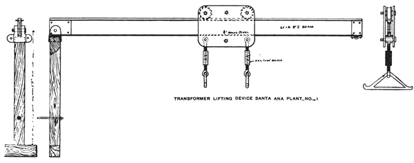 |
| Transformer Lifting Device Santa Ana Plant No. 1 |
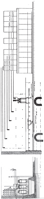
The pipe line from the forebay to power house No. 3 is 8490 feet long and has a fall of 1960 feet from the water level in forebay to power house floor. The main Hue consists of 2485 feet twenty-six-inch pipe, 2150 feet twenty-four-inch riveted pipe, and 3450 feet twenty-four-inch lap-welded, with eighty-two feet eighteen-inch and 233 feet fourteen-inch pipe for branch lines to the four different units. All twenty-four-inch and twenty-six-inch pipe is continuous riveted pipe, varying in thickness from No. 14 to 0000, B. W. G., and all other twenty-four-inch pipe is lap-welded from seven-sixteenths to seven-eights inches in thickness. The eighteen and fourteen-inch branch pipes are also lap-welded of five-eights and one-half-inch metal, respectively. The material used for all these pipes is open-hearth, box-annealed steel, of 40,000 to 60,000 pounds per square inch tensile strength. All joints, except those used in laying the eighteen and fourteen-inch branches, are riveted; the latter are made with solid welded steel flanges. The branching of main pipe lines is done by means of cast steel Ys and curves having radii from nine to twelve feet. All flanges on these specials are also of cast steel. The line is fully equipped with air valves, blow-offs and pressure alleviators, which make accidents caused by the formation of a vacuum or by the presence of water hammers impossible of occurrence.
 |
| Arrangement of Transformers and High Tension Wiring, Santa Ana Plant No. 1 |
The joints used in laying the force main of the pipe line of Mill Creek plant No. 3 were made in the following manner: On riveted pipes all joints are made by means of a single row of rivets, such joints being in what is known as "round seams." The details for this riveting are shown by the sketch on page 39. The description of the work is as follows. The holes are punched with a multiple punching machine in a manner to make them all meet fairly when the sections of pipe are pulled together. The joint is then riveted, cold rivets being used on all gages lighter than No. 8 B. W. G. and hot rivets for all heavier gages. After the seams are riveted the pipe is chipped and caulked to make a perfect union, metal to metal, entirely around the circle of the joint. Where the lap in the joint occurs the metal of the overlapping sheet is also chipped and caulked in the same manner. After this is done the inside ^and outside are painted with asphaltum to protect the pipe against the action of water and soils.
| |||
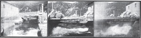
| A Study of the Santa Ana Tail Race, Showing, in the Last Two Views, Full Load and No Load Discharges Respectively |
The joints on lap-welded pipes fire made in two different ways. On the lighter pipes what is known as the "expanded" or "bump" joint is employed. One end of the pipe section is swelled sufficiently to permit the other to enter it. Holes are punched through both thicknesses of metal where the insertion of one pipe into another is made and the riveting is done by means of hot rivets in the same manner as shown for round seams for riveting pipes in the drawing herewith. The joint is also chipped and caulked in the same manner as on riveted pipe. For the lighter gages of lap-welded, expanded-joint pipe one row of rivets is employed in making the joint, but for metal having a thickness of from five-eighths to three-fourths of an inch, two rows are used, and the rivets staggered in the same manner as when making straight seams on riveted pipe. The diameter of rivets used for these heavier pipes is seven-eighths of an inch. A portion of the lap-welded pipe is made with solid welded steel flanges. The joint employed in laying these pipes is also shown in the sketch which applies to the lap-welded pipe with shell three-fourths of an inch in thickness. The principle of this joint is that a groove runs entirely around the flange, as shown in the separate drawing, into which is squeezed a five-eighths-inch circular rubber gasket. This gasket is made in the form of a circle and not of the exact diameter of the groove in the flange. It is inserted into this groove and pressed into the space shown when the flanges are drawn together so as to have their faces come metal to metal. The principle of this joint is excellent, since the possible escape of water from the interior of the pipe, and the pressure against the rubber gasket which may be due to it, simply tend to press the gasket more firmly into the recess in the flange, thereby making an absolute guarantee against leaks. There is no chance for this gasket blowing out, since the flanges are drawn up by means of the bolts so as to have the two metal faces in perfect contact.
SANTA ANA POWER HOUSE NO. 1.
A substantial concrete building, having an inside length of 127 feet and being thirty-six feet in width, houses the machinery that constitutes the plant known as Santa Ana Station No. 1. The building is, in fact, one single piece of monolithic concrete, and no iron is used in its construction except that necessary to support the crane and steel roof. This crane spans twenty-seven feet of the building, one side being supported on the wall nearest the water wheels, and the other side being supported by iron columns practically in line with the switchboard Each generator, with its Pelton water wheel, is mounted on a base plate having three common bearings, and the four generators and water wheel sets which constitute the plant are arranged with shafts parallel to the long way of the building. The water is directed upon the wheels by means of a deflecting nozzle which leaves the receiver at right angles, and when the stream is deflected from the wheel it is projected through a tunnel beneath the floor of the power house and outside the building through a covered duct. The latter part is lined with boiler plate to a point about seventy-five feet from the wheel, where these separate ducts are united to a common canal twelve feet wide and ten feet deep. The accompanying illustrations and drawings give the details of this very interesting piece of construction, which it is confidently believed is the peer of any similar work to be found elsewhere. The water in the transverse section of the tail-race is kept at such a height that it is just awash with the wheel-pit linings, or practically three feet below the buckets of the wheels. This results in a cushioning effect, which quiets the jet when the nozzle is deflected. So far as known, this arrangement is the first of its kind ever applied to wheels of the Pelton type, and by means of it each individual wheel and its wheel pit are easily accessible without interference from the discharge water from the other wheels, and as a result the arrangement permits the exercise of diligence in the maintenance and inspection of that part of the hydraulic plant.
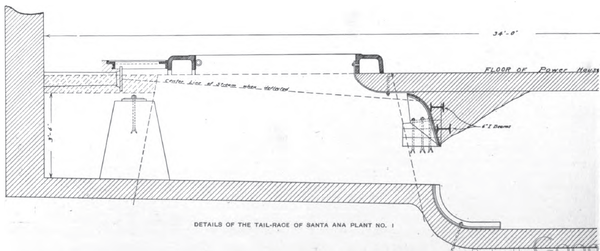 |
| Details of the Tail-Race of Santa Ana Plant No. 1 |
Each generator and wheel are, as stated, mounted upon a common cast iron base with three bearings. The generators are of the revolving field type, running at 300 revolutions per minute, and being each of a capacity of 750 kilowatts. They are wound with a bar winding for 750 volts, and the armature is three-phase Y connected, delivering current at fifty cycles. The plant at present contains four such units, with foundations for four more similar units, to be installed when the second pressure pipe is put in. The exciter units are three in number, each having a capacity of thirty kilowatts at 175 volts, and are direct connected to suitable Pelton wheels.* (*Described in detail in THE JOURNAL, Volume XI, page 31, January, 1901.) The generator wheels are governed by Type F Lombard governors, which operate to deflect the nozzle, and are actuated by water at a head of approximately 120 feet, supplied by an independent reservoir. This is in turn furnished by water taken from the main pipe line. These governors were the first of the type named that were ever manufactured, and the entire plant and system was constructed with the idea of maintaining water wheel regulation of the highest possible degree of perfection. In this the expectations of the company's engineers have been fully realized, for they contend that better governing has been obtained in the hydraulic plant of the Santa Ana station than it is possible to secure with a steam plant, unless it be in the use of steam turbines. The exciters are governed by small mechanical sectroidal governors. The water wheel and exciter governors were furnished by the Pelton Water Wheel Company, as was also the receiver, together with its connections and valves. The generators were furnished by the General Electric Company.
| |||
| A View in Mill Creek Canyon |
The generator switchboard is a simple arrangement, with double busbars, having a separate panel for each generator, and total output panel, with suitable recording and integrating instruments, and two transformer panels, each containing two sets of transformer switches. All of the switches are of the quick-break knife type and have been perfectly satisfactory. The exciter panels are also in duplicate. All low tension wiring is of 700,000 circular mils, cable, which is carried from the transformer switches to the transformers through an air duct which runs beneath the floor. The twelve 2so-kilowatt transformers used are all of the air-blast type and are carried on I beams, each group of three being placed in a row across the transformer pit, which is of sufficient depth to allow a man to get underneath the transformers should it be necessary. Through these transformers the generator potential of 750 volts is stepped up to 33,000 volts in Y-connection, the neutral point being grounded at the station.
As is clearly shown in the illustration on page 24, the high potential board is mounted in a gallery over and slightly to the rear of the generator board, and it consists of a transformer panel for each three-phase group of transformers, two line panels, and one connecting panel, which consists of a double busbar arrangement with double throw switches. By means of these switches the connecting panel may be divided in half, making it possible to operate on either of the two transmission lines on one-half of the bank of transformers, so that either half of the high-tension board may be rendered dead for repairs or cleaning. This high-tension board is half-way between the inner rail of the crane and the wall of the building, facing the tail-race, while the trans-formers are in line with the space back of the low-tension board on one side and the exciters on the other. All high-tension apparatus is protected by General Electric short-gap lightning arresters having forty-eight gaps to each leg, and the arresters are so adjusted that an arc will hold at about 42,000 volts for a fraction of a minute without injury to the arrester equipment or impairing its usefulness. The highest operating voltage is 34,700.
The Santa Ana station has been in absolutely continuous operation since January 22, 1898 and there is yet to occur the first shut-down of one moment's duration due to the failure of any part of the canal line, power house or its equipment, and, as far as the machinery of the power house is concerned, there have been no repairs except of a very minor nature, such as renewing a small valve or a small pipe here and there, and other repairs to worn-out nozzle tips and a few buckets for the exciter wheels. Not a single bucket for the large wheels has been changed or altered in any way during the entire period.
THE 33,000-VOLT TRANSMISSION LINE.
The great artery of the transmission system of The Edison Electric Company, is the main transmission line, formerly known as the Southern California Power Company's transmission line, which runs from the Santa Ana Canyon station almost in a direct line to the Second Street substation (substation No. 1) in the city of Los Angeles. This is the far-famed 33,000-volt eighty-two-mile line, which for years was unequaled, both in length and voltage, by any line in the world. When the building of this line was projected under the voltages named, the project was strongly opposed by electrical manufacturing companies, who extended no encouragement whatever towards aiding the enterprise, and, in fact, the scheme met with very little encouragement of any character until after it had demonstrated its success. From the outset it was granted that the weakest point in the line was the insulators, for at that time none had been used in regular commercial service at a potential in excess of 15,000 volts, and to more than double the voltage at a single bound was deemed to be a very hazardous and even foolhardy undertaking. Mr. O. H. Ensign, the electrical engineer of the company, was strong in his contention that the plan was entirely feasible and that it would prove of the greatest reliability, an opinion which has since received the unqualified endorsement of not only long service, but of generally universal adoption. It should be recorded as a matter of interest that a representative of C. S. Knowles, of Boston, agent of the Imperial Porcelain Works, gave Mr. Ensign samples of insulators then in use and samples of porcelain which the Imperial Porcelain Works proposed to use in the manufacture of 33,000-volt insulators. Absorption tests showed a radical difference between existing styles of porcelain insulators and the porcelain which it was proposed to use for the insulator in question. A sample lot of these insulators were eventually turned out at Trenton, where they were examined both by Mr. Sinclair and Mr. Ensign, whereupon the latter took an insulator in its soft state, and with his pocket knife whittled it into the shape now known as the Redlands type of porcelain insulator. Insulators of this pattern were duly furnished by Mr. Knowles, it being expressly stipulated that every insulator was to stand a salt water test of 66,000 volts. Eventually sufficient insulators were secured to withstand the test applied, and these columns* have told heretofore of some experiences encountered in making the test. It is worthy of note that there have been but few insulators lost by puncture since this line was constructed. A cross section of the Redlands insulator as installed on the Santa Ana-Los Angeles transmission line, with dimensional data, accompanies this article, and there will also be found a view of the cross-section of the porcelain insulator used on the original 10,000-volt lines of the Redlands Electric Light and Power Company, together with cross-sections of other insulators of equal interest.
| |||
| Some Features of the Hydraulic Work of Mill Creek Plant No. 2. |
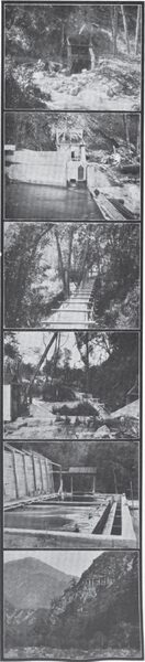
| |||
| Building A Stretch of Fluming on Mill Creek Plant No. 3 |
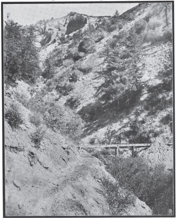
This very remarkable transmission line consists of two circuits of No. 1 B. & S. Gage M. H. D. copper wires arranged in an isosceles triangle on a single pole line and supported on insulators of the type described. The line is eighty-three miles long and the weight of copper thereon amounts to 632,000 pounds.
In spite of the fact that the line wires are only from eighteen to twenty-four inches apart in some places, arcs do not hold long between wires when once it is started. The porcelain insulators on this line were all tested with a ten-kilowatt transformer to 70,000 volts before being put up. It was in the erection of this line that the fact was first forcibly demonstrated that insulation breakdown tests of insulators must have plenty of transformer capacity behind them, otherwise the leakage over the insulator may be heavy enough to seriously pull down the voltage of the testing transformer. Only one insulator has proven defective on the entire 83 miles in two years of operation. Of course, some have been broken by being shot at. The high tension sides of the transformers are connected Y-fashion, and the neutral grounded. This, of course, throws a greater strain than would otherwise be on the insulators, especially when the poles and cross-arms are wet, as there is 19,000 volts between wires and ground. Strange as it may seem, there is one case on record where a line wire lay directly on the cross-arm without setting the arm on fire.
Another peculiar thing noticed on this line is that when a broken insulator permits leakage to the pin and cross-arm and thence down the pole to ground the cross-arm is burned only where it touches the pole. The electrical contact between the cross-arm is evidently not very good. The eighty-three miles of line is looked after by two patrolmen, and both of these have other dutiesone at the power house and the other at a substation. When a bird or wire goes into the line it starts an arc which in most cases lengthens itself out in the air until it breaks. When a short of this kind occurs the attendants at the substation usually succeed in pulling through without shutting down the synchronous motor-generators, of which there are a number on the line. This is done by instantly tripping the circuit breakers on the direct-current ends of the motor-generators and then opening the field switches of the synchronous motors just far enough, so the field circuits are closed through a resistance by means of a small auxiliary contact on the switch. The synchronous motors are left on the line as induction motors without load for a few seconds until the power is all right and have been brought up to speed; then the fields are thrown in again, the motors jump into step, and the circuit breakers are closed on the direct-current side to resume regular operation. No fuses are put in the high-tension line or at the power house, except that the generators are fused to four or five times their capacity. Occasionally one of these fuses blows, but is replaced before the service is interrupted. Generators of the type used connected to water wheels do not give sufficient current on short circuit to endanger their windings, hence the practicability of running without fuses. Indeed, fuses would be very much of a nuisance on these lines.
|
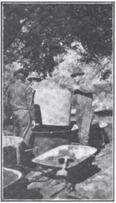
|
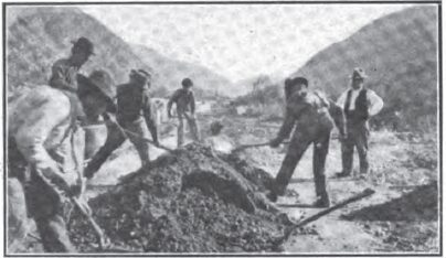
|
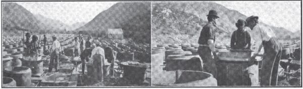
It has been claimed that climatic conditions are favorable in Southern California for such transmissions. They are as regards freedom from lightning, although there is some of this, and there is plenty of rain. The most trying thing, however, is the ocean fog which sometimes drifts up the valley and covers everything with moisture. In such cases the pole tops at high points on the line are luminous at night, but the leakage on the eighty-three miles of line is less than seventeen kilowatts at such times. General Electric short gap arresters are used on this line with one-sixteenth gap between cylinders, and one gap to every 400 volts potential across their terminals, making forty-eight gaps in all. There is a static discharge continuously between the gaps for about half the distance to ground. The balance of the gaps are silent.
One of the features of the main transmission line, which is not only original but extremely effective, consists of so-called rams-horn air-brake pole line switches, details of which are made sufficiently clear by the photographs appearing on page 41 as to seem hardly to warrant detailed explanation, especially in view of the fact that dimensional data appear on page 45 of this issue. The principal of operation, furthermore, is so similar to that of the ramshorn blow-out lightning arrester, which first appeared as an accessory to the Thomson-Houston arc system, that its action must be readily understood. These ramshorn switches are cut into the mainline whenever an important branch is taken from it, and at other points, such, for instance, as on each side of the city limits of Pomona, through which the main line passes. The entrance of the main line in Los Angeles substation No. i is by these switches, which have been found for this voltage in transmission lines to be perfectly satisfactory in operation. As proof of their effectiveness it may be stated that out of twenty-seven air-blast, 30,000-volt transformers in use on this system, not one single dollar has been spent for repairs since these switches were placed in operation in January, 1898. Marked facility in handling high-tension circuits is got through the use of these switches, as the arrangement makes it possible to carry the load up to the point of break, should such occur on the main line, by steam on one side and by waterpower on the other.
This switch is not as formidable looking as the long break switches in use on most lines of this kind. The distance between the switch jaws is thirteen inches. Extending upwardlv from the jaws is a pair of horns made of line wire. Connection between the switch jaws is made with a piece of round brass rod attached to a long, dry, wooden handle. The brass rod and handle is kept from falling out of the switch jaws when the switch is closed by the spring catch shape of the jaws as shown in the section. When it is pulled down out of the switch jaws the arc is carried up between the horns by the heated air and is broken. This switch has never failed to break the circuit when opened under any conditions which have so for existed. Of course, it is seldom used, as most of the circuit opening is done first on the low tension side of the transformers at both power house and substations. The main use of these switches when opening live loaded circuits would be in case a transformer should begin to burn out. Each substation has these switches put in each transformer circuit as well as in the high tension lines as they enter the substation. The insulators on the line are put on wrought iron pins with a wooden sleeve four inches high, covering the pins between the insulator and the cross-arm.
The eighty-three-mile transmission line is thus sectioned, with outdoor switches at the end of each section for transferring from one line to another for making repairs without shutting down the substations. At spans across streams these insulators are arranged to take the strain according the diagram on page 51. The company is decidedly in favor of porcelain as against glass for high tension lines because of its mechanical strength.
MAKING THE CEMENT PIPE FOR THE WATERWAY OF MILL CREEK PLANT NO. 3
It is of value to note with what entire success the telephone line is operated on the transmission pole lines, even though the transmission line is run with a grounded neutral. It shows that there is very little leakage on the transmission line. The telephone wires are run five feet below the transmission line on pony glass insulators.
Some odd stories are told regarding the behavior of the 33,000-volt current. A wireman climbing up over a transformer case got his head so near one of the high-tension wires that an arc jumped across the air space to his head. The voltage between the transformer case and ground was about 19,000 volts. The man was picked up for dead, but was resuscitated. A hole was burned in his skull and the skin burned off the soles of his feet. Skin was grafted on to replace his loss and the man recovered, at last accounts being in the employ of the San Joaquin Electric Company at Fresno, Cal.
| |||
| Making the Cement Pipe for the Waterway of Mill Creek Plant No. 3. |
|
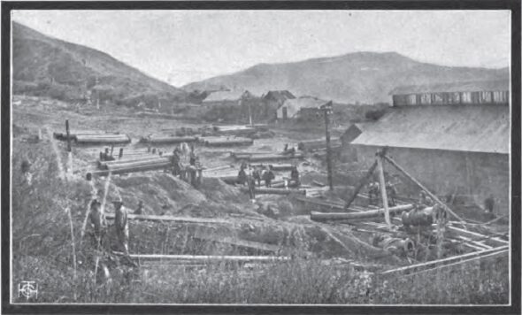
| |||
| The Pipe Yard at Mill Creek Plant No. 3 |
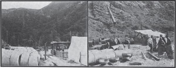
The most peculiar freak of the 33,000-volt current, however, happened in the Santa Ana Canyon. One of the transmission line poles was guyed to a large boulder by means of an eye-bolt in the boulder. One night an arc got started from one of the lines to the guy wire. An employe of the company passing along saw the flame, and, rushing to the nearest telephone told the power house that a pole was on fire and to get ready to shift over onto the other line. The employes at the power house spent a few anxious minutes watching the instruments and preparing to switch over on a moment's notice. Minute after minute went by, but no sign of any line disturbance showed on ammeter or wattmeter, nor had there been any noted previously. A party was sent out on the line, but could not find the burning pole. All was dark. The next morning the pole was found. The arc had broken itself, but not before the boulder, through which the current was seeking ground with 19,000 volts behind it, had sweat great drops of slag and burst. The company has evidently discovered a new way to break up rock. The volume of current required must have been very small, as it was not detected by the station instruments.
Mr. J. A. Lighthipe engineer for the Pacific Coast District of the General Electric Company, and under whose supervisionfrom the view point of the manufacturers of the machinerythe Santa Ana Canyon plant was installed, thus describes, in an admirable magazine article* [* Cassier's Magazine, Volume XVII, page 3, November, 1899.], the experience had in starting that which was then the highest voltage line in the world:
"In starting this plant in February, 1899, the potential was raised very slowlya step at a time. At about 16,000 volts the lightning arresters started jumping, and it was necessary to increase the air gap in them about double. The brush discharge from the balls of the lightning arresters probably bridged over at least half of the air gaps. At about 18,000 volts the instruments at each end of the line gave indications that the current was jumping somewhere. Lowering the potential a few hundred volts stopped it, only to start again as soon as it was attempted to raise the potential. The plant was then shut down and a thorough inspection of the eighty-three miles of line was made without finding any trace of the trouble. The plant was then started at night, and the potential was raised to keep the current jumping, and the trouble was soon discovered. The line men, in running the wires, had crossed the line between two poles so that one wire hung about an inch below the other. This, from the ground, looked like a transposition, and so was not discovered. At about 18,000 volts the current would jump from one wire to the other, then run along the line, increasing its arc until it would break, then jump to the shortest distance again. The station agent at Ontario saw the fireworks two miles down the track and reported by telephone. As soon as the lines were cleared the potential was run up to 33,000 volts with no more trouble."
POWER PLANT NO. 1 ON KERN RIVER.
Preliminary work on this plant was commenced by the California Power Company, to whose interests The Edison Electric Company succeeded, some time near the close of the year 1900. The first work consisted of preliminary surveys, with some tunnel excavations, which was carried on continuously until September, 1901, when the California Power Company begun the construction of necessary roads for reaching the proposed powerhouse location. The above work was all completed and the property transferred to The Edison Company during the year 1902. Since that time The Edison Company has continued the work by constructing all the necessary roads and trails for reaching the various portions of the line and by carrying on the excavation of the various tunnels.
| |||
| The Lower End of the 2000-Foot Cable Lift on Mill Creek Plant No. 3 |
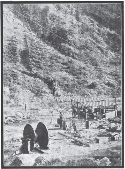
At the present time there is a force of approximately 200 men at work excavating the tunnels and doing other work looking to the speedy completion of the plant. Work is now in progress on fourteen of the twenty tunnels, and preparations are being made to open up the remaining six tunnels within the next thirty days. The work on the tunnels is now being prosecuted by hand drilling, which, in the near future, will give way to the operation of machine drills. With this object in view The Edison Company is now installing a construction power plant of 300 kilowatts capacity, and three fourteen by eighteen duplex air compressors, each to be driven by seventy-five horsepower induction motors. The construction plant will consist of two McCormick turbines working under a net head of forty-five feet, direct connected to two 150-kilowatt three-phase generators. The location of the plant is on the river where a natural waterfall occurs, making it possible to install this plant with only 800 lineal feet of flume for conducting the water to the wheels.
| |||
| A Generator Frame and A Three Phase Transformer for Mill Creek Plant No. 3 |
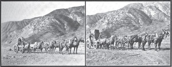
The transmission line is now being erected to distribute the power from this station to the various air compressor stations along the line. There will also be sufficient power from this construction plant to drive fans for ventilating the various tunnels and for supplying lights to the tunnels while they are being constructed. It is expected to have the construction plant, with air compressors and air drills, in operation by the first of February, after which the work of driving tunnels will progress very rapidly.
The conduit for power plant No. I will consist principally of tunnels, of which there are twenty altogether. The length of these tunnels will each be as follows:
Tunnel No. 1.. 645.4 feet
" 2 .. 2515.5 "
" 3 .. 777.7 "
" 4 .. 3909.1 "
" 5 .. 454.5 "
" 6 .. 1548.1 "
" 7 .. 1805.6 "
" 8 .. 1007.8 "
" 9 .. 3798.1 "
" 10 ... 2059.7 "
" 11 ... 3214.2 "
" 12 ... 2579.5 "
" 13 ... 2184.4 "
" 14 ... 2149.4 "
" 15 ... 4378.6 "
" 16 ... 3764.7 "
" 17 ... 1498.2 "
" 18 ... 1893.9 "
" 19 ... 2126.6 "
" 20 ... 743.9 "
Total . 43,054.9 "
All the tunnels will be lined with concrete on the inside up to a height of seven feet, which is the level of the permanent flow of water. Carrying capacity of the tunnels will be 350 second-feet of water. Between some of the tunnels will be short flumes for spanning ravines. Level connection in the majority of cases is made by means of an adit driven on the side of the ravine, in which case no flume is required.
The list of flumes to be constructed on this power plant is as follows, flume No. 1, 1120.6 feet; flume No. 2, 153.5 feet; flume No. 3, 164.1 feet; flume No. 4, 115 feet; flume No. 5, 65 feet; flume No. 6, 85 feet; total, 1703.2 feet.
All the flumes, with the exception of flume No. 1, will be constructed on steel trestles, the sides and bottom of the flume being made of two-inch redwood plank. Flume No. 1, which crosses a low flat depression between tunnels No. I and No. 2, will be erected on a wooden trestle eight feet above the ground with box of two-inch redwood plank. The flumes will be of the same size as tunnelsnine feet wide by seven feet deep.
From the end of the hydraulic conduit, consisting of flumes and tunnels as above described, the water will be taken through an incline tunnel to the power station, where it is delivered under a pressure of 872 feet. The incline tunnel will be driven through the solid rock and lined with a circular tube seven feet in diameter made of No. 10 B. W. G. steel plate, riveted. This tube will be covered with a heavy coating of asphaltum on both its surfaces, and the space between the outer side and the rock sides of the tunnel will be filled with a mixture of concrete, of Portland cement one part, and sand and gravel seven parts. The concrete will be thoroughly mixed and rammed into place between the tube and rock sides of the tunnel in such a manner as to form a perfect wedge. The purpose of the interior tube will be to prevent the seepage of water through the concrete and bedrock of the incline tunnel while the pressure of the water will be resisted by the latter. From the lower end of the force main, constructed by means of the incline tunnel and lining, as above stated, branches made of heavy steel pipes, each twenty-four inches in diameter, will be run to the various water wheel units of the power house.
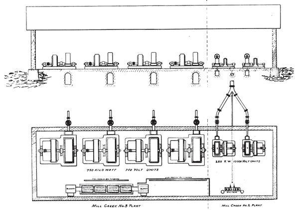 |
| Plan and Elevation of Mill Creek Plants Nos. 2 and 3 |
The intake for power plant No. 1 will consist of a masonry dam twenty feet high constructed on bedrock, and a gate tower with grizzlies and regulating gates for diverting the water into tunnel No. 1. The dam will have a large lake, about three-fourths of a mile in length, in which all of the sediment in the river will settle before being admitted into the power plant. A secondary tunnel driven at a level below the foundation of the dam will drain the lake at a point some distance above the intake tunnel and will be used as a sluice-way for expelling the sand and detritus collecting in proximity to the intake.
The capacity of power plant No. 1 will be about 18,000 kilowatts at the generating station when the hydraulic conduit is delivering its full flow of water. The low water of the year 1902 at the company's intake would give a minimum amount of power of 10,000 kilowatts at the power station.
It has been decided to erect a fire-proof station of masonry and steel, in which will be installed 15,000 kilowatts in water wheels and generators. The location for the power house is immediately above the intake of the power plant of the Power Development Company, of Bakersfield. The site is a very excellent one, the foundation being granite bedrock. The Edison Electric Company expects to complete this plant and have power delivered in I/OS Angeles within two years from date.
POWER PLANT NO. 2 ON KERN RIVER.
The Edison Electric Company has completed the preliminary surveys and begun work on a second plant above its plant No. 1 on Kern River, to be known as power plant No. 2.
The diversion point for this proposition is a short distance above the junction of Kern River and Clear Creek. The length of canal required will be eleven and a half miles, which will be constructed of conduit similar in character to the work now being done on power plant No. 1. The net fall available for the second plant will only be 317 feet, and the power house location is immediately above the intake of power plant No. 1. The work on this plant has not progressed sufficiently to give further data at this time, but it will be possible to install a station with the capacity of from 5,000 to 6,000 kilowatts.
POWER PLANT NO. 3 ON KERN RIVER.
The preliminary surveys have been completed and some tunnel excavation has been commenced on a third proposition, located above the town of Kernville on the North Fork of Kern River.
The length of line surveyed is twelve and a half miles, giving a net fall of 760 feet at the power station. At this point it will be possible to install another plant having a capacity of approximately 15,000 kilowatts. The plans and work on this plant have not progressed sufficiently to give detailed information, but it is likely that construction will be of a character similar to that on power plant No. 1.
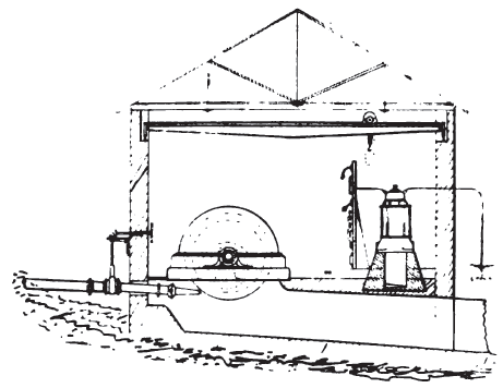 |
| Section of Mill Creek Plant No. 3 |
Still further up the North Fork and above power plant No. 3 are other power rights, which will give two more propositions with a large output of power. These are now being surveyed for the purpose of determining the location as well as method of development.
From aneroid readings and hand level observations made by the engineers of the company the following approximate data may be given:
Power plant No. 4 will have a fall of about 1,000 feet and the length of canal will be approximately fifteen miles.
Power plant No. 5 will have a fall of 1,200 feet and an approximate canal length of twenty miles.
It will be possible to develop from these two propositions approximately 30,000 kilowatts delivered to the transmission system during ordinary low stages of the water in the river.
|
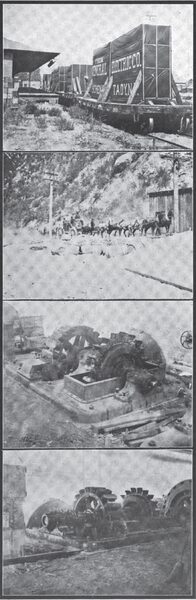
THE SUBSTATIONS.
The first substation which is entered after leaving the power house is that at Redlands, some eight miles distant, in which are installed three 280 kilowatt General Electric air blast transformers, reducing from 33,000 to 10,500 volts, the primaries of which are Y connected, and these transformers, with a suitable potential regulator, are used to tie into the busbars of the old Redlands system on the 10,000-volt switchboard in this substation. These transformers are connected through a panel on the main switchboard, which contains indicating and recording wattmeters and voltmeters that can be plugged into either leg of either side of the switch. It also contains proper lamp synchronizing devices for throwing the two systems together through 10,000-volt oil break switches of the General Electric type. The ammeter on this section of the switchboard is calibrated to read in kilowatts at 10,500 volts, and it is possible by the use of the regulator and indicating wattmeter and this recalibrated ammeter to keep the power factor very close to unity and still run the two systems at various voltages. The potential regulator is of the I. R. T. motor-driven type, built by the General Electric Company.
The further transformer installation in the Redlands substation consists of a bank of three 11,000 to 2500 air blast transformers, each having a capacity of 200 kilowatts, for supplying the city of Redlands and vicinity, and also two natural draft transformers of the General Electric type, stepping down from 10,000 volts to 360 volts, for the operation of a 100-kilowatt rotary converter, which supplies 500 volts direct current for the operation of the Redlands street railway. This rotary converter is a ninety-six kilowatt machine with six poles, and its speed is approximately 1000 revolutions per minute. A very interesting piece of apparatus which is now being installed in this substation, consists of the 200-kilowatt motor generator set built by the General Electric Company, the motor of which is wound for 10,500 volts and the generator is to deliver 550 volts direct current for railway service. This unit is to be started with a compensator.
| |||
| Mill Creek Plant No. 2 Prior to the Extension |
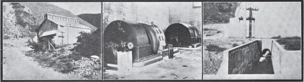
In addition, the Redlands substation contains a steam plant, consisting of three Stirling water tube boilers, rated at 285 horsepower, each of which carry a pressure of 150 pounds per square inch. Each of these boilers contain 220 three and a half inch tubes, and are fitted for oil burning. The engines therein consist of a compound tandem Hamilton-Corliss sixteen by thirty with thirty-six-inch stroke, which runs at 118 revolutions per minute, and a Wheelock simple Corliss engine having a bore of twenty inches by stroke of forty-two inches and running at seventy-six revolutions per minute. These engines drive, respectively, a sixteen pole, three-phase, 400-kilowatt, 2400-volt generator at a speed of 375 revolutions per minute, and a General Electric sixteen-pole, three-phase, 2400-volt, 225-kilowatt generator, also running 375 revolutions per minute. The exciters for these machines are, respectively, Westinghouse, 125-ainpere, and General Electric, seventy-two-ampere, 125-volt machines From this substation is operated the distributing system of the city of Redlands, as well as four 10,000-volt, three-phase, circuits, supplying light and power to San Bernardino Valley.
The next substation on the 33,000-volt line is located at Colton Cement Works, in which are installed three 100-kilowatt, oil-filled, water cooled transformers, supplying current for the operation of induction motors in seventy-five, fifty, forty, thirty and ten horsepower sizes in the Colton Cement Works, as well as for the operation of a 200-horsepower synchronous motor in the same plant.
At Pomona is located the largest substation on the transmission line between Redlands and Los Angeles, and it contains three 150-kilowatt oil-filled transformers and a General Electric constant current arc transformer having a capacity of fifty lights. Regulation is secured through the use of a forty-three-kilowatt I. R. T. motor-driven regulator. This substation supplies Pomona and a number of smaller stations thereabouts with light, as well as a large territory in which water is pumped for irrigation purposes. In addition the company is now installing in this substation three I5o-kilowatt, 30,000-volt to 11,000-volt transformers for supplying additional power to the outlying territory.
At Puente another substation contains three 150-kilowatt transformers, stepping down from 31,000 to 11,500 volts, for supplying a circuit twenty-three miles in length which runs through Fullerton, Anaheim and Orange, with a seven-mile branch to Whittier, and ends in the town of Santa Ana, with a small substation in each of the towns named. The substation in Santa Ana contains three seventy-five-kilowatt oil-filled transformers, stepping down from 11,000 to 2200 volts, with an I. R. T. regulator and a fifty-light constant current General Electric arc transformer with primary wound for 11,000 volts. The company also operates a gas plant in Santa Ana. This was built by the Western Gas Construction Company of Fort Wayne, Ind., and has a capacity of 100,000 cubic feet daily.
At Shorb another branch is tapped from the transmission line, and this branch, which shows the same construction that characterizes the main line, consists of No. 6 copper. Its length is four and four-tenths miles, and it ends in a substation at Pasadena in which there is installed six 150-kilowatt, 30,000-volt to 2200-volt transformers and one 100-light General Electric series arc transformer. This substation occupies the old plant of the Pasadena Electric Light and Power Company, and of the steam machinery which it formerly contained one 35O-horsepower Sioux City Corliss engine has been retained, as well as a Westinghouse 300-kilowatt generator of the 2200-volt, Y-connected, revolving armature type, which carries a part of the local day load in event the main transmission line is temporarily cut out for alterations or repairs.
| |||
| Intake, Sand Box and Tail Race of Mill Creek Plant No. 3 |
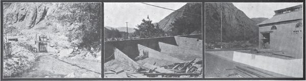
The main transmission line terminates, as stated, in the Second Street substation in Los Angeles. This is known as Los Angeles substation No. 1 and it is the principal one in the city. Its electrical transmission equipment consists of six 250-kilowatt air-blast transformers., connected in two banks, Y on primary and delta on secondary, each reducing from 30,000 to 2200 volts. Three of the three-wire three-phase local lighting circuits are controlled by I. R. T. regulators, and the remaining two circuits, which are still of the single-phase variety, are provided with single-phase regulators of the M. R. type. This substation also contains a steam plant capable of generating 1500 horsepower.
Los Angeles substation No. 1, commonly known as "the Second Street plant," is an auxiliary steam station of no mean magnitude, for it contains practically 2000 horsepower in boiler, engine and generator capacity. If to this be added the 4000 horsepower received by the transmission lines from Santa Ana plant No. 1 for conversion into three phase 2200-volt current, it will be seen that the output of the combined steam plant and substation aggregates a total of about 6000 horsepower. To particularize, the steam station contains, one, 650 horsepower compound condensing St. Louis Corliss engine, running at eighty-five revolutions per minute, having cylinders measuring sixteen by thirty inches by a stroke of forty-eight inches. This engine is belted to a 600-kilowatt, 2200-volt, three phase, Y-connected General Electric generator, also, one 300-horsepower simple Ideal engine, and one 400-horse-power compound Ideal engine, both of which are belted to a jack-shaft from which is belt-driven a 650-kilowatt, three-phase, Y-connected General Electric motor-generator set having 2200 volts on the alternating current side and 550 volts on the direct current side. Clutch pulleys and suitable switchboard connections enable this motor generator set to be utilised for various self-evident functions. For instance, when driven by the engines, it will deliver power to either or both the 2200-volt, three phase, or the 500-volt direct current services, or when the jack shaft is cut out it enables the transmission lines to carry the direct current power load, or with the engines it preserves effectively an economical balance on the direct current power load, also, one 300-horsepower Chandler engine, which operates a beltdriven three-phase General Electric, 2200-volt, Y-connected generator having a capacity of 300 kilowatts.
The boilers of the Second Street steam plant are of the water tube type, one-half of which were furnished by the Babcock & Wilcox Company and the remaining half by the Stirling Company.
| |||
| Some Construction Views Taken During the Erection of Mill Creek Plant No. 3 |
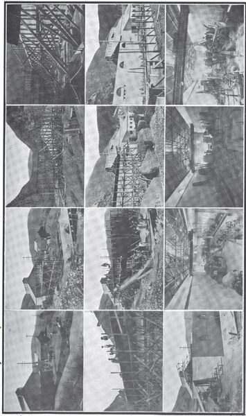
The second substation in the city of Los Angeles, known as the Los Angeles substation No. 2, is fed by a 2200-volt current from substation No. I, and in this second substation are installed two 300-kilowatt three-phase synchronous motors, each direct connected to two 150-kilowatt, 140-volt, direct current generators, and also one 640-kilowatt synchronous motor direct connected to two 300-kilowatt, 140-volt, direct current generators, which, together with the 140-cell, type H, chloride battery of the Electric Storage Battery Company, operate in parallel on the Edison three-wire distribution in the downtown district. This battery has a capacity on an eight-hour discharge of about 800 amperes, with a maximum discharge rate of about 3000 amperes, and it is kept floating upon the system throughout the twenty-four hours, and in case of short circuits on the transmission system, it is always ready to take care of the interruption on the three-wire system. It is also used to help out over peak loads and is discharged to its normal capacity each day. It has proven its usefulness in that for three years there has not been so much as a wink in the three-wire system from this station.
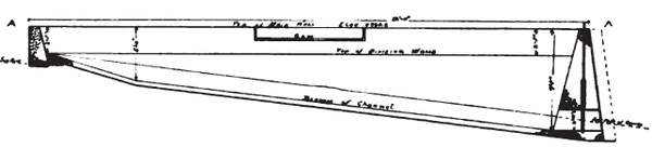 |
| Elevation of the Sand Box |
With the exception of the 100-kilowatt, 500-volt, generator in substation No. 2, which is driven by belting from one of the smaller motor-generator sets, the company's entire 500-volt direct current power load in the city is operated from suitable generators located in substation No. 1.
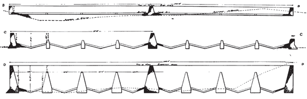 |
| Details of the Sand Box for Mill Creek Plant No. 3 |
At a point some six miles from the Santa Ana power house a branch line is tapped from the main line 30,000-volt transmission and continued up Mill Creek Canyon to No. 3 power house, in which are installed four 750-kilowatt, 430 revolutions per minute, General Electric generators of the revolving field type, and four 750-kilowatt General Electric transformers of the air-blast type, which are noteworthy in that they are the first three-phase transformers in large sizes ever installed on the Pacific Coast. With the exception of these transformers, the electrical features of the plant in Mill Creek plant No. 3 are very similar to those in Santa Ana Canyon, but the hydraulic features are radically different, particularly in the fact that the wheels are to operate under what is undoubtedly the highest head of water applied to any power plant, namely, 1960 feet. Another portion of this article contains exhaustive details of the hydraulic features of this most interesting plant.
THE SYSTEM OF DISTRIBUTION.
The Edison Electric Company supplies currents in six varieties to the following services:
First110-volt incandescent and arc lights, and also 110-and 220-volt motors on a continuous current Edison three-wire underground system in the business district of Los Angeles.
Second500-volt continuous current motors on a two-wire underground system in the same district.
ThirdContinuous current series arcs in the same district and in Santa Ana.
Fourth110-and 220-volt lamps on the two-and three-wire secondaries of an alternating current, fifty-cycle system in the residence districts of Los Angeles, and all parts of Pasadena, Puente, Whittier, Fullerton, Orange, and Santa Ana, Pomona, Claremont, Highlands and Redlands, with 2200-volts on the primary, the three-phase, three-wire system being used in the larger places.
FifthAlternating current series arcs in Pasadena, Pomona and Redlands.
Sixth110-, 220-, 440-, 550- and 2080-volt three-phase motors in the above cities and towns, and the surrounding country in the San Gabriel, San Bernardino, Riverside, La Habra and Santa Ana valleys from 10,000-, 2200- and 280-volt primaries.
To supply such services the company runs in parallel one water power plant in Santa Ana Canyon, delivering 33,000 volts, two water power plants in Mill Creek, delivering 33,000 volts, and three steam plants at Los Angeles, Pasadena and Redlands, while its fourteen substations, including the storage battery plant in Los Angeles, are centers of distribution for the power so generated.
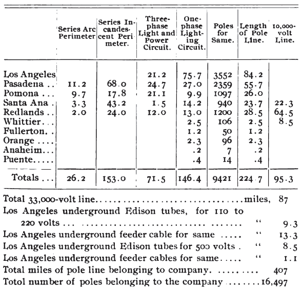 |
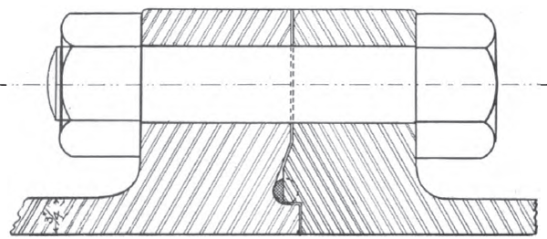 |
| Detail of Pipe Joint in the Force Main of Mill Creek Plant No. 3 (The Dotted Semicircle Shows the Form of Gasket Before Compression |
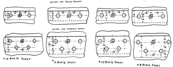 |
| The Beveled Joints in the Force Main of Mill Creek Plant No. 3 |
| |||
| Where the Pole Line Leaves the Santa Ana Canyon |
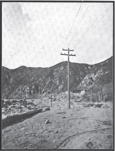
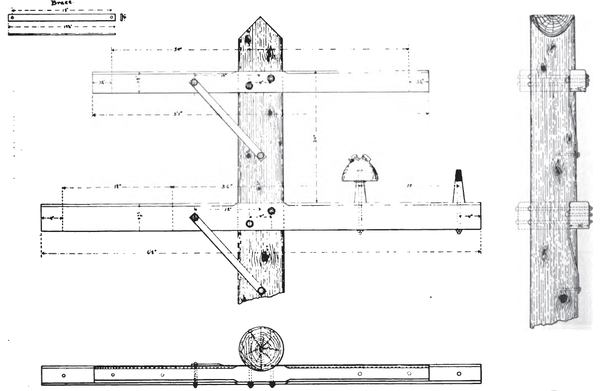 |
| Arrangement of Insulators and Cross-Arms on the 33,000-Volt Pole Line of Santa Ana-Los Angeles Transmission |
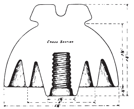 |
| The Redlands Type Imperial Porcelain Insulator |
| |||
| Two Views of the 33,000-Volt Pole Switch on the Santa Ana-Los Angeles Transmission |
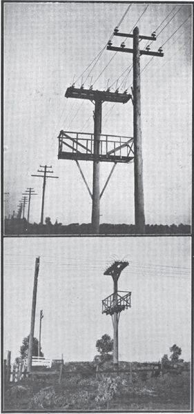
SOME GENERAL OBSERVATIONS.
The same building which houses Mill Creek station No. 3 also contains station No. 2, in which are, as has been previously stated, two 250-kilowatt, General Electric, 11,000-volt generators and two thirty-five-kilowatt 125-volt exciters, together with the accompanying switchboard equipment. The method of operating this system as a whole, with so many plants tied together, is one that is accomplished on the basis that the main transmission line is to be relied upon for continuous service. It is a very uncommon thing for switches to be pulled out and for machines to be synchronized for any other purpose than cleaning up. Short circuits are, however, bound to occur on the line from various causes, and the procedure adopted on the circuits of The Edison Electric Company are not only unique, but are undoubtedly of great effectiveness, as the voltage chart on page 51, which was one selected by the writer at random from last year's charts, will certainly attest. In case of a short circuit it is the custom that the Santa Ana station, which supplies the most power, will stay on the line to the full capacity, maintaining strong generator fields. The other plants of the system will either break the fields of their generators or throw the water off the exciter wheels, as may be deemed best, and this action will immediately throw a strong impedance on the line which will tend to break the arc, and if the short is not due to a wire down or something equally serious, everything will be in perfect condition for operating again within five or ten seconds, whereupon the machines which have broken fields will be pulled into synchronism with the generators in the Santa Ana station as soon as the arc breaks. In this procedure the apparatus must depend upon the governors of both engines and water wheels to keep the speed approximately correct. When the arc breaks all machines being on the line with fields open act as induction motors and are pulled so closely into step that when the fields are again energized they come fully into step. In exceedingly rare instances, in fact only three times since the line was put in operation, has it occurred that this plan of handling short circuits would not operate, but as the usual thing, interruptions due to malicious meddling, baling wire, or possibly to large birds, are met and overcome in this manner with perfect satisfaction.
| |||
| The Placid Flow of the Lower Kern River Gives No Suggestion of Its Turbulence Further Up the Canyon |
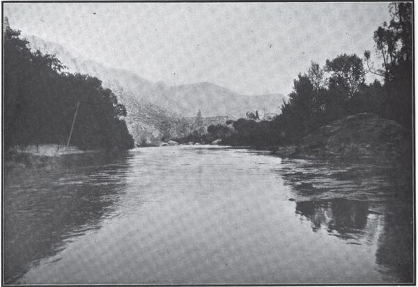
It is a matter of interest in alternating current working, to call attention to the fact that inasmuch a? there are fifteen different sizes and types of generators operating on this system, there must of course be a considerable variation in the wave forms of them, and yet hunting of generators is unknown on the system. The charging current, which, it was thought when this line was built, might become a serious item, is an utterly negligible quantity. As recent measurements made on the main transmission Hue by single circuits proved that, although the apparent energy- lost was approximately 600 kilowatts, the loss in actual energy- was about seventeen kilowatts. One of these lines is transposed at every fifty-first pole, and the other one at every eighty-eighth pole, and it has also been found that the line which has the greatest number of transpositions takes 15 per cent, less charging current to carry the same load.
Before completing the section discussing the generating plants of the system, it should be added that there is now under construction in Los Angeles a steam plant having a capacity of 6000 kilowatts, in which the units will be of the capacity of 2000 kilowatts each, to be driven by steam turbines of the manufacture of the General Electric Company. This plant will tie into the general transmission system, and upon its completion the other and less up-to-date steam plants which the company has acquired from time to time will be dispensed with. The system will be thoroughly modern and of high-class quality in every respect. The site of this plant will become the main receiving point for all transmission lines this company is now operating or has under construction, and in consequence it will also be a substation of considerable size.
| |||
| Fording the Kern River at Extreme Low Water During the Summer of 1901. |
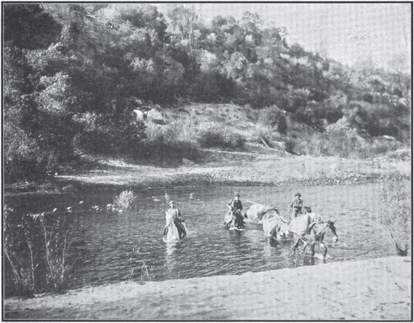
The electrical engineer of this company is a firm believer in the superiority of motor-generators over rotary converters for use with a frequency as high as fifty cycles, and lie claims as high as an all-day efficiency for them as for rotary converters where the substation is supplying both alternating and direct current, as is the case in most transmission plants. If rotary converters are used two sets of static transformers must be put in, one set for supplying the rotaries and the other for supplying alternate current for distribution. With motor generators one set of static transformers only is needed, and they can be worked at higher efficiency than two sets. With synchronous motor generators there is no trouble with pumping or surging as there is likely to be with high frequency rotaries and the high commutator speed of the rotary is done away with. The synchronous motors are always started as induction motors with unexcited fields.
FINANCIAL.
If the business of The Edison Electric Company be viewed from its financial side it will be found to be as sound as are the engineering features of the enterprise, and no concern could have sounder bases. The condition of the finances of the company were shown in a statement presented by Mr. John B. Miller, its president, to Messrs. E. H. Rollins & Sons, Perry, Coffin & Burr and N. W. Harris & Co., bankers, a syndicate formed in the spring of 1902 for the purpose of financing the consolidation of all the Edison companies, on October 29th, last. From this it appears that The Edison Electric Company is a corporation having its chief place of business in the city of Los Angeles, California, duly organized for the purpose of acquiring, constructing and operating plants for the purpose of generating, transmitting and selling electrical energy; developing and constructing water power plants for the purpose of generating electricity, and for the purpose of generating and distributing gas, and for all other purposes kindred to and consistent with an electric and gas corporation.
| |||
| A Tunnel in the Kern River Power Development |
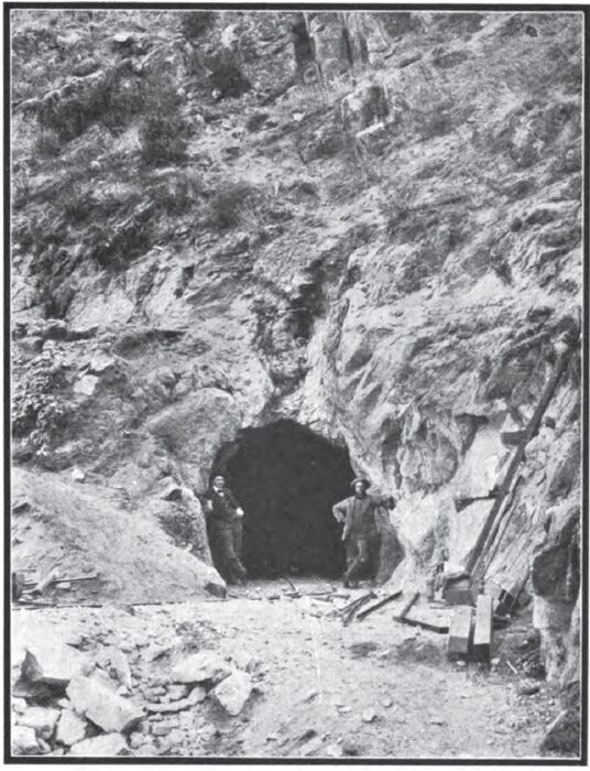
It has acquired the franchises, rights, property and all other assets of the following corporations, namely, the Edison Electric Company, Los Angeles, Cal.; the Pasadena Electric Light and Power Company, Pasadena, Cal.; the Santa Ana Gas and Electric Company, Santa Ana, Cal.; the Redlands Electric Light and Power Company, Redlands, Cal.; the Southern California Power Company, Los Angeles, Cal.; the California Power Company, Los Angeles, Cal., and the Mountain Power Company, Los Angeles, Cal. As a result, The Edison Electric Company, by reason of its acquisition of the above corporations, operates generating stations and distributing systems on one general system, connected in the aggregate by 165 miles of 33,000-volt and 10,000-volt transmission lines. Furthermore, its distributing system covers the cities of Los Angeles, Pasadena, Highlands, Redlands, Colton, Riverside, Pomona, Claremont, Whittier, Fullerton, Orange and Santa Ana, as well as the intervening territory, and it consists of 300 miles of overhead three-wire, three-phase, 2200-volt incandescent and power circuits, arc and incandescent street lighting circuits, and, in the business district of Los Angeles, an underground system, constructed under General Electric Company's patents, while in Santa Ana the company operates a 100,000-cubic foot gas works, with gas distributing system covering the streets.
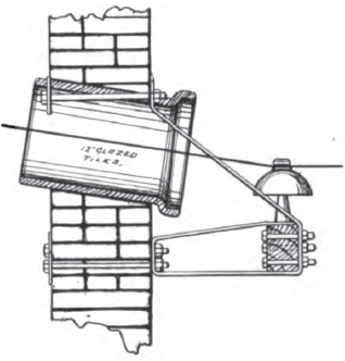 |
| Method of Introducing 30,000-Volt Wires Into Stations |
The company operates its system under ample and favorable franchises, and because of its ability to produce a large percentage of its power from water power, it is enabled to operate at a low percentage of cost. It should also be added, by way of summarization, that its total present generating capacity in water power plants is 8758 horsepower, which is reinforced by a present capacity of 2934 horsepower in steam plants, these respective plants being located as follows:
Southern California Power Company's water power plant, in Santa Ana Canyon, San Bernardino County, 4000 horsepower.
Redlands Electric Light and Power Company's water power plants, Mill Creek Canyon, San Bernardino County, No. 1, No. 2 and No. 3, of 1250 horsepower, 625 horsepower and 3000 horsepower capacity respectively.
Redlands substation and steam driven plant, 834 horsepower capacity.
Pasadena Electric Light and Power Company's steam plant, 600 horsepower.
Edison Electric Company's steam plant at Los Angeles, 1500 horsepower.
Total generating capacity in water power plants, 8875 horsepower, reinforced by 2934 horsepower in steam plant capacity.
| |||
| Six Interior Views of the Steam Auxiliary Plant in the Redlands Substation |
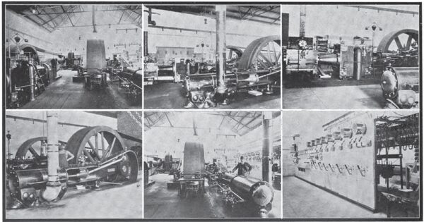
Furthermore, and as already stated, in order to provide for the company's rapidly increasing business, work is proceeding on a 28,000-horsepower plant on the Kern River, with a 116 mile transmission line to Los Angeles, and a 5334-horsepower steam plant of the most modern type, at Los Angeles, for emergency purposes.
| |||
| The Generators of the Redlands Auxiliary Plant |
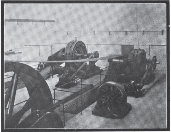
These properties, covering the most fertile and populous sections of southern California, serve an estimated population of 235,820, compared with 140,540 population in 1890, and with every indication of still further increase in the near future. The company is largely owned by residents of southern California, and its officers and directors are men of large commercial interests and strong financial standing.
The official report by the company for the year ending September 30, 1902, gives the following statement of earnings, which may be accepted as authentic:
Gross earnings $445,110.46
Operating expenses, including taxes, insurance and maintenance charges $209,518.55
Net earnings $235,591.91
Interest on all outstanding bonds $125,220.00
Surplus earnings $110,371.91
The bond interest in the above statement is for the entire mortgage debt now outstanding, whereas the earnings include no income from the Redlands hydraulic plant, No. 3, which will soon be operating with an additional maximum capacity of 4000 horsepower.
It is conservatively estimated that the earnings for the year ending September 30, 1893, will be:
Gross earnings $475,000.00
Operating expenses, including taxes, insurance and maintenance charges $225,000.00
Net earnings $250,000.00
And that with the completion of the 28,000-horsepower plant on Kern River, the productive capacity of the company will be increased between 100 per cent, and 200 per cent, over its present capacity.
The company is capitalized as follows:
Preferred stock, 5 per cent, cumulative $4,000,000.00
Common stock 6,000,000.00
Total $10,000,000.00
Outstanding, preferred $2,000,000.00
Outstanding, common. 400,000.00 $2,400,000.00
Bonds authorized $10,000,000.00
Reserved to retire underlying sub-company bonds $893,000.00
Held in escrow under conservative restrictions of trust deed for acquisition of other plants, development of water power and other permanent extensions and additions 7,550,000.00 $8,443,000.00
Bonds of the present issue outstanding.. .. $1,557,000.00
The first and refunding 5 per cent, gold bonds of The Edison Electric Company, amounting to $1,000,000, are dated September 1, 1902, and are due September 1, 1922, they being in denominations of $1000. Their redemption is optional on any coupon date on and after September 1, 1907, at 110 and interest. Interest is payable on March 1st and September 1st at the office of the Los Angeles Trust Company, Los Angeles, trustee, or at N. W. Harris & Co., New York. Principal payable at the United States Mortgage and Trust Company, New York, co-trustee, where bonds may be registered. The price of these bonds is 102 and interest, subject to prior sale and advance in price.
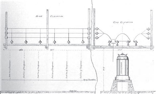 |
| Type of Substation Switches on 33,000-Volt Lines |
The trust deed contains a strong sinking fund provision, which requires the company to deposit annually with the trustee, beginning September 1, 1907, 10 per cent, of its annual net earnings. In case, however, of the lease, sale or consolidation of the company's property as a whole, such payments shall thereafter be 1-1/2 per cent. of the par value of the bonds outstanding at the date of the payments. The sinking fund shall be used to retire the bonds of the company, at not exceeding the call price of 110 and interest. This bond is non-taxable when held in the State of California.
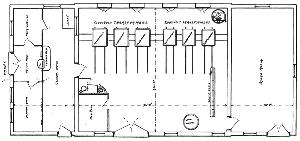 |
| Floor Plan of Type of Substation on 30,000-Volt Lines for Towers of From 2000 to 10,000 Inhabitants |
Referring again to future development, the company, in order to provide for a further large increase of its business, has begun an hydraulic development in connection with its Kern River water rights, as stated, which will require an expenditure of approximately $2,000,000 during the next two and one-half years. The funds for this expenditure are to be secured by the sale of bonds from escrow to the extent of 75 per cent, of the actual cost, but not exceeding $1,500,000, and the sale of the company's preferred stock for the balance, thus preserving a strong cash equity in the property over the bonds issued from escrow. When this development is completed, the water from this river, which rises on Mount Whitney (15,000 feet elevation), in the Sierra Nevada Mountains, will be used under an effective head of 840 feet, and it is proposed to install machinery with a capacity of 28,000 horsepower. The installation is designed to deliver a maximum of 18,000 horsepower in electricity in Los Angeles, no miles distant. From reports of competent hydraulic engineers, based upon the Government records of the stream covering a period of seven years, the minimum delivery should be 7000 horsepower.
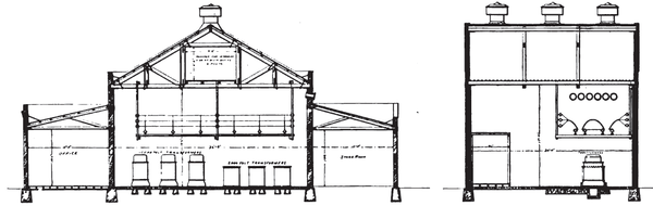 |
| Longitudinal and Sectional Elevation of the Type of Substation on 30,000-Volt Lines for Towns of From 2000 to 10,000 Inhabitants |
In view of the character of and the prospective growth in the population and community served, the strong franchise situation and the large amount of water power controlled, it is indisputable that these bonds will ever be regarded as a safe and desirable investment.
In conclusion it should be stated that the trustees of the Edison Electric Company are: Messrs. John S. Cravens, of Pasadena; James C. Drake, of Los Angeles; Henry Fisher, of Redlands; John B. Miller, of Pasadena; Frederick H. Rindge, of Santa Monica; Wm. R. Staats, of Pasadena; H. H. Sinclair, of Pasadena; J. S. Torrance, of Pasadena; Walter S. Wright, of Pasadena; while its executive officers and heads of departments are: Messrs. John B. Miller of Pasadena, president and treasurer; Henry Fisher of Redlands, first vice-president; J. S. Torrance of Pasadena, second vice- president; H. H. Sinclair of Pasadena, third vice-president; Wm. R. Staats of Pasadena, secretary; Walter S. Wright of Pasadena, counsel; W. L. Percey of Pasadena, assistant secretary and assistant treasurer; W. H. Workman Jr. of Los Angeles, technical assistant to the president; A. E. Halsey of Los Angeles, auditor; F. C. Finkle of Los Angeles, chief hydraulic engineer; O. H. Ensign of Los Angeles, chief electrical and mechanical engineer; C. A. Copeland of Los Angeles superintendent of distribution; A. L. Selig of Los Angeles, general agent; D. A. McGilvray of Pasadena, purchasing agent.
To the several of these gentlemen who have supplied invaluable assistance in the way of information, and to Messrs. Putnam and Valentine and to Mr. B. J. Pierson, superintendent of powerhouses, who have supplied photographs, the thanks of the writer are cordially extended.
