[Trade Journal]
Publication: The Electrical Engineer
New York, NY, United States
vol. 25, no. 522, p. 477-480, col. 1-2
·
·
[Missing text]
·
·
where it joins the Union Elevated loop operated over by all the elevated roads of Chicago. It is about 8.3 miles long. At its southern end it is a competitor of the excellent suburban service of the Illinois Central. The rest of the way its chief competitors are electric and cable surface lines.
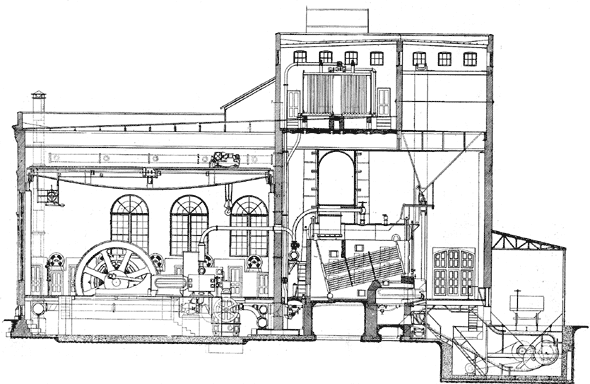
The power station shown in Fig. 2 is located at Fortieth and State streets, adjoining the structure. This is a location desirable from many standpoints. In the first place it is near the centre of distribution or load centre of the road, being approximately 3.3 miles from the northern end and 5 miles from the southern. It is also convenient to coal, as a railroad runs along Fortieth street directly past the building, and a coal siding will be run in along the east side of the power house between it and the structure, as shown in the accompanying plan and end elevation, Figs. 3 and 4. From the coal cars the fuel is shoveled or dumped into the hopper which surrounds the car as shown, and falls into a coal crusher under the coal track. This coal crusher is driven by an ironclad C & C motor. From the crusher it is taken by John A. Mead conveyors and distributed along the coal storage bins under the roof of the boiler room.
 |
| Fig. 4. Transverse Section of Power House, South Side Elevated Railroad, Chicago. |
From the bins and hoppers it is fed down to the mechanical stokers. Between the hoppers and the discharge pipe which delivers fuel to the stokers, is an automatic weighing device furnished by Borden & Selleck, which causes coal to be discharged 224 pounds at a time; the number of discharges being recorded, the coal supplied to any boiler is easily calculated. The mechanical stokers are of the Babcock & Wilcox make, as are also the boilers.
There are eight of these B. & W. boilers, each provided with 64 square feet of grate surface and rated to evaporate 12,000 pounds of water per hour, or 600 h. p. with an engine consumption of 20 pounds per indicated h. p. per hour. These boilers were given a cold water test of 300 pounds per square inch after being set up in the power house. For boiler feeding there are three Blake compound feed pumps, 10 x 7 x 12 inches. The exhaust of these pumps is run through a Warren Webster feed water heater. The feed water supply may be drawn from two sourcesfrom the main engine condenser discharge or from the city water mains. In the water mains from which the station water supply is drawn, two meters are placed, and a water meter is also placed in the supply pipe of each boiler. A double system of feed water piping is installed whereby the feed water heater may be cut in or out and the Green economizers may be cut in or out. These two Green economizers are put over the smoke flue of the boilers and draw the hot gases from a point in the main smoke flue midway in the bank of boilers, and discharge into the stack just above the main flue. When the economizers are to be thrown out of use the economizer flue in the middle of the bank is closed and the smoke discharged direct into the stack. The coal conveyors as well as the economizer scrapers are driven by C & C motors. The ashes are discharged into conveyors in the boiler room basement and lifted to a bin at the top of the boiler room, from whence they can be drawn at convenience.
The stack is a riveted steel plate structure, lined with fire brick. The plates of which it is composed are inch thick at the bottom and grow thinner toward the top, where they finally come down to inch. The total height of the stack above foundation is 200 feet. The diameter of the steel casing at the bottom is 19 feet, at the top 13 feet 9 inches. The fire brick lining is 9 inches for the first 57 feet, 8 inches for the next 50 feet, 6 inches for the next 50 feet, and 4 1/2 inches for the last 43 feet.
The boilers are piped to the main headers by 8-inch pipes. The main headers are 12-inch, of which there are two, joined at the middle by a 9-inch copper expansion bend in the middle. These headers rest on rollers supported on brackets along the wall separating boiler and engine rooms. The pipes to each of the 1,200 h. p. engines are 8 inch. Copper bends are used throughout. S. J. McLeod was the contractor for the station piping. The engine room shown in Fig. 5 contains four cross compound, horizontal, condensing, Allis Corliss engines, each 26 x 54 x 48 inch stroke. They run 8o revolutions per minute and develop 1,200 horse power at the most economical point of cut-off but will run as high as 2,000 horse power. Each engine is direct connected to an 800 kilowatt Westinghouse generator. Each engine has an independent Reynolds condenser which takes water from the tank at the bottom of the cooling tower and discharges into a 20-inch pipe which runs to the top of the cooling tower: A 3o-inch free air exhaust main also runs the length of the building. This exhaust is made of riveted steel pipe. A plain gravity oiling system is piped to all the machinery. After running through the bearings the oil passes through Turner filters and is pumped back to the tank in the upper part of the station. A Westinghouse air pump supplies compressed air for cleaning out armatures. Air is piped to each generator. A Morgan traveling crane spans the engine room. It is rated at 60,000 pounds carrying capacity, is 59 feet long and equipped with a General Electric motor.
The dimensions of the power house are 200 by 112 feet. The boiler room is 200 by 48 feet and the engine room zoo by 59 feet. The engine room has capacity for two more units like the four already in and the boiler room will contain enough more boilers to make up for the two engines. The height of the engine room from the floor to the bottom of the roof girders is 34 1/2 feet. There is a 9 1/2 foot basement under the engine room. The roof girders are 4 feet deep.
The switchboard is white marble, equipped with G. E. switches and circuit breakers and Weston ammeters and voltmeters. The four generator panels are 1,500 ampere nominal capacity each and have the usual G. E. equipment of positive and negative quick break switches, ammeter, circuit breaker and field rheostat controller. The terminals of the field rheostats are on the panels but the resistance itself is in the basement. There is a main panel through which the total station output flows and this panel is designed to carry 8,000 amperes. This panel is equipped with an 8,000 ampere ammeter, a recording wattmeter, a Bristol recording voltmeter and two Weston voltmeters, one for constant use, the other to be plugged in at any generator panel before throwing that machine in. The feeder panels each are arranged to take care of two feeders. At the bottom of a panel near the floor are two single pole switches. Just above the switches is a circuit breaker; above this the two ammeters are placed and finally at the top of the panel the other circuit breaker. This arrangement has the advantage of being more compact than the usual arrangement of one feeder to a panel, but it has the disadvantage of bringing the lower circuit breakers uncomfortably near the attendant. One feeder panel of small capacity is devoted to the station motors and lights and has a recording wattmeter.
The power house is in charge of A. L. Hadin, chief engineer, a gentleman of marked ability in this line of work and formerly chief engineer and master mechanic of the Aurora Street Railway.
THE COOLING TOWER.
The greatest interest of course centres around the immense cooling tower, shown in Fig. 6, for supplying cool water to the condensers, this being the largest electric railway power house ever built to use condensing water not supplied by a natural water supply. The word immense, however, does not exactly apply to the tower that has been built, for considering the horse power it has been designed for it is remarkably compact. It is 16 1/2 feet wide, 64 feet long and 34 feet high. Under the tower proper is a tank 6 feet deep so that the total height of the structure is 40 feet. The tower is constructed under the designs of the Wheeler Condenser & Engineering Company, known as the Barnard system. A 20-inch discharge pipe is run the length of the engine room and all the condensers discharge into it. At the end of the engine room next to the cooling tower this pipe runs vertically up the outside wall to a height of 48 feet which is 12 1/2 feet above the top of the tower.
| |||
| Fig. 7. Switchboard and C & C Motors Driving Fans for Cooling Tower of South Side Elevated Railroad, Chicago. |
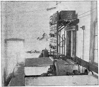
This vertical pipe is left open at the top as an emergency overflow in case the pressure rises above a certain amount in the condenser discharge. At a level with the top of the tower a 20-inch pipe leads off horizontally from the vertical discharge pipe and is supported on brackets on the wall of the power house. From this 20-inch horizontal pipe a 10-inch branch pipe is led over to the tower every 11 feet 8 inches. These branch pipes discharge into headers from which the water is sprayed over wire nets which are hung vertically like curtains in the tower. It then trickles down over the wire netting to the tank at the bottom during which process it cools by contact with the air and by evaporation. The tower is built of steel plate and was constructed by the Toblin & Hamler Manufacturing Company which company also made the stack. At the bottom of the tower air can be drawn in by ten to-foot fans. Two fans are on each shaft, as shown in Fig. 6. The tower adjoins the north end of the engine room and the five fan shafts are run through into the engine room where are five 18 horse power C & C motors, shown in Fig. 7, direct connected to the shafts, and set on a gallery over the toilet rooms. The maximum speed of the fans is 175 rev. per minute. On the motor gallery is a switchboard for the fan motors at which they can be connected in various combinations of series and parallel to give different speeds. It is not expected that all the fans will be necessary except with the station fully loaded in the hottest weather. The rated engine capacity of the plant is 4,800 horse power at present and will ultimately be 7,200.
CURRENT DISTRIBUTION SYSTEM.
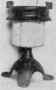
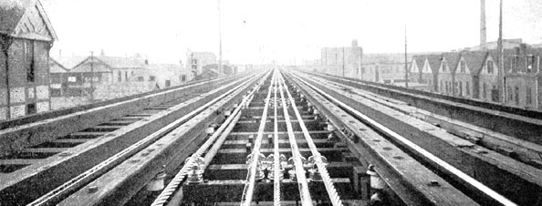
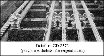
The standard Chicago elevated third rail system is of necessity employed to deliver current to trains as this road uses the Union loop in common with the other electric elevated roads. The third rail is located at one side of the track, as will be seen in Fig. 8, just outside the guard rail and the top of the third rail is 11-1/2 inches and is supported by porcelain insulators, shown in Fig. 9, every 6 feet.
| |||
| Fig. 9. Porcelain Insulator Used for Insulating Third Rail, South Side Elevated Railroad, Chicago. |
·
·
The feeders are bare copper cable and are run in a box between the tracks supported on centre bearing glass insulators with iron pins covered with wood and wood cross arms. From the power house north, feeding 3.3 miles at double track, there are feeders as follows: One of 1,000,000 circular mils cross section, including 730 ft. of 500,000 circular mils; one of 500,000 circular mils, 16,327 ft. long; one 1,000,000 circular mils, 7,461 ft. long.
| |||
| Fig. 8. Track Construction and Location of Feeders, South Side Elevated Railroad, Chicago. |
 |
From the power house south, feeding 5 miles of double tracks and the yards and siding, the feeders are as follows:
One of 1,000,000 circular mils 5,890 ft. long; one of 1,000,000 circular mils 10,462 ft. long; one of 1,500,00 circular mils 16,048 ft. long (including 986 ft. of 500,000 circ. mils); one of 1,500,00 circular mils 22,822 ft. long; one of 500,000 circular mils 23,122 ft. long.
| |||
| Fig. 10. Method of Hauling Up Feeders by Means of A Steam Locomotive, South Side Elevated Railroad, Chicago. |
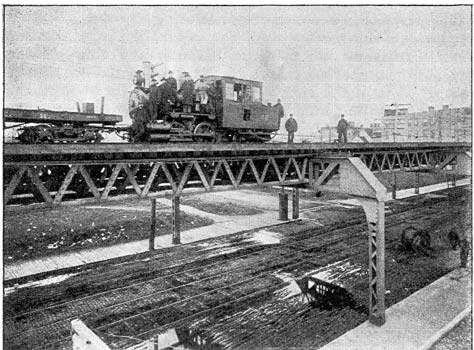
The present feeder system is calculated for 120 cars. At each crossover the feeders go under the structure. In laying the feeders the Electrical Installation Company made use of a steam locomotive. The cables were drawn from a reel under the structure and the locomotive proved an invaluable adjunct in drawing through the feeders in unbroken lengths; this operation is shown in Fig. 10.
It will be seen from the description that standard line material was made use of very largely so that the cost was reduced much below what it would be if special insulators, etc., had been used.
The voltage used is 600 to 650.
In the yards at 63rd street in some special work of such complicated nature that it was impossible to secure a continuous contact between the shoes and the third rail. This together with the impossibility of safely having a third rail in the shops led to the equipment of all the cars with an ingenious little rubbing contact overhead trolley. A trolley wire has been strung over the special work in the yards and in the shops. The trolley is the design of B. J. Jones of Sargent & Lundy's staff. It consists of an arch of brass rod held in balanced tension by springs at each end so that it normally stands vertical but can be deflected either way. This trolley is only 14-1/2 inches high and the trolley wire is hung but a short distance above the car roof. When a car runs under the trolley wire this trolley yields one way or the other to the wire and no attention is required by the trainmen.
CAR EQUIPMENT AND MULTIPLE UNIT SYSTEM.
The Sprague multiple unit system which is being employed on this road has been so much discussed lately that it is hardly necessary here to give more than a brief statement as to the principles of the system. As the name multiple unit implies, each car is a complete motor car in itself, equipped with motors and controlling apparatus. The great ingenuity of the plan is displayed by the arrangements whereby the motors on the whole train may be controlled from any point on the train. The apparatus to safely accomplish this is somewhat complicated and as yet Mr. Sprague has authorized no publication of the many details and whatever articles have appeared purporting to give details have been far from correct. The general principles, however, are as follows: The motors under each car are controlled by an ordinary street car controller located under one hood of the car. This controller instead of being operated directly by a manual lever is connected to a small pilot motor. To operate a car the motorman simply controls the pilot motor circuit. In fact the whole system of train control simmers down to this one problem of properly controlling these pilot motors which work the controllers on the various cars. On each platform of every car is a small controlling box whereby the motorman controls the pilot motor circuits of the various cars. The cars are connected electrically by plug couplings. It makes no difference how many cars are in a train the motors all act in synchronism or approximately so. The rate of acceleration of a train is not governed by the motorman, but automatically. An automatic throttle governs the pilot motor in such a way that the pilot motor can advance the controller from one notch to the next higher only when the current flowing through the armature of one of the motors under cars falls below the amount for which the throttle is set. For example, if the throttle is set for too amperes the pilot motor will move the controller ahead a notch every time the current falls below too amperes so that practically a constant accelerating current is kept flowing through the motors until the controller is at the highest point. Provisions are made to automatically shut off current from a car in case of failure of the supply and to turn it on again by steps if the supply is resumed and the motorman still has his controlling handle on.
A great deal of argument might be indulged in as to the merits and demerits of the system, but time and experience will settle the question better than any amount of argument. As to the efficiency and cost of maintenance of the multiple unit system for performing a given service as compared with the performance of the same service by a locomotive or motor car at the head of the train there will naturally be considerable difference of opinion. One thing, however, must be admitted by all, namely, that it affords a traction on the drivers by distributing the motors through the train which can be obtained in no other way at present on an elevated road where the weight of locomotives is limited by the strength of the structure. This gives two advantages either or both of which may be made use of. It gives a traction on the rails which permits a faster acceleration and consequently faster schedule than can be obtained in any other way provided motors of sufficient capacity are provided; or it permits the running of longer trains than any locomotive could haul. Either one of these items may mean the attraction of enough traffic to offset any increase in operating expenses which the multiple unit system may involve. Faster schedule time means the attraction of passengers to the road and longer trains mean the ability to comfortably carry more passengers per hour if trains are already operating on the shortest permissible headway.
Just what the schedule time on the South Side Elevated will be it is of course impossible to say until the road is in full operation electrically. The guaranteed schedule of the new electrical equipment is 15 miles per hour, which is but slightly above the present steam schedule. The results will be watched with much interest.
| |||
| Fig. 11. Showing Contact Shoe on Side of Truck and Vestibule for Motorman on Cars of South Side Elevated Railroad, Chicago. |
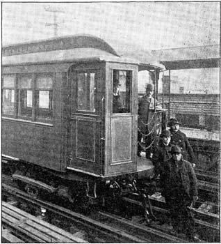
In changing the rolling stock from steam to electrical equipment the old truck was taken from under one end of each car and a McGuire elevated motor truck substituted for it. On this motor truck two G. E. 57 motors of 50 horse power were mounted. Thus half the weight of the car body and the weight of the two motors is on the driving wheels or about 60 per cent. of the total weight. Contact shoes are mounted on each side of each truck. It was necessary also to have a vestibule for protecting the motorman on the front platform, shown in Fig. 11. A folding vestibule was designed, the two sides of which swing back against the end of the car out of the way of gate or passengers when the vestibule is not in use. Up against the front wall of the vestibule are the air brake valve, air pressure gauge and electric trolley handle. The Westinghouse air brake with which the cars were formerly equipped is still used. Each car has its own electrically driven air pump made by the Christinsen Engineering Company. This pumps air into the auxiliary reservoir under each car. An additional air hose and train pipe has been put in addition to the regular Westinghouse train pipe for the purpose of connecting together the auxiliary reservoirs and equalizing the reservoir pressure throughout the train.
The Gold electric car heaters are used and are hung under the seats. When giving their maximum effect they take 22 amperes per car at 600 volts.
The maximum speed of the motor equipment on these cars is about 26 miles per hour.
| |||
| Fig. 12. A Multiple Unit Train of Five Cars, South Side Elevated Railroad, Chicago. |
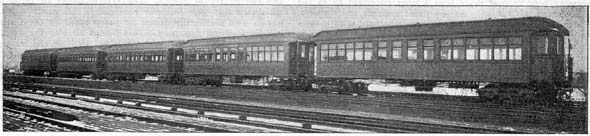
There are 120 cars equipped with motors and 3o more cars which have been wired for electric lights, heaters and pilot motor circuits, but are without motors. These can be run in among motor cars of multiple unit trains. A multiple unit train of five cars is shown in Fig. 12.
The change of the cars from steam to electric equipment involved much more work than is apparent at first thought. It had to be accomplished without interfering with the steam service. Five coaches at a time were taken to the Wells & French
·
·
[Missing text]
·
·
