[Trade Journal]
Publication: The Electrician
London, England
p. 319-320, col. 2,1
BENNETT'S INSULATORS.
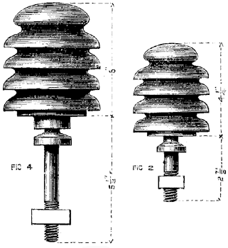
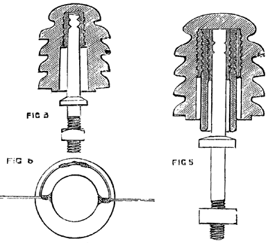
Early in 1882 Mr. Alfred R. Bennett designed the two insulators illustrated herewith, his object being to improve the insulation of the lines erected for the National Telephone Company by Messrs. D. and G. Graham, of Glasgow. The wires taken over by the National from the late Bell and Edison Telephone Companies and others were seriously deficient in this respect, so much so that overhearing between wire and wire was common, and in many cases was obviously due, not to induction, but to actual leakage. These wires were all constructed on the double-shackle system, which, indeed, before the introduction of the insulators now under consideration, was the one universally adopted for over-house telephone lines in this country. The double shackle is shown in Fig. 1. It consists of two porcelain cups having iron bolts right through them, which bolts are connected by four galvanised iron bands or straps, with a third bolt passing through the support. The ends of the spans of wire are looped round each cup and joined by a soldered cross-connection. This arrangement has much mechanical merit, for it confines the effects of a break in a wire to the span upon which it occurs, and prevents the wire falling into the street in the event of a fracture of a porcelain cup. But its insulating properties are very inferior, for at each cup the current finds two roads to earth, which, everything else being equal, would, by the law of derived circuits, reduce the insulating efficiency of a single shackle cup to one-fourth of that of an upright insulator, and of the double-shackle to one-eighth. But in practice, especially in wholly in excess of the gain of eight times derived from the position of the wire at its summit and the existence of only one road to earth. A combination of the mechanical functions of the shackle and the insulating properties of the upright was, therefore, required, and this Mr. Bennett appears to have accomplished in his design. The insulators shown in Figs. 2, 3, 4, and 5 are used in precisely the same way as shackles, each span being terminated round the insulator, and joined through to the next by a soldered cross-connection. (Fig. 6.) When light wire, such as Nos. 16 to 20 phosphor-bronze, is employed, both spans are terminated round the topmost groove. With heavier wire it is better to terminate each span in different grooves, preferably the first and second from the top. When unusually long spans are unavoidable it is well to reduce leverage by using the second and third or even the third and fourth grooves, the insulation under these circumstances, owing to the dry cup, still being far superior to anything obtainable from shackles. The terminating of the wires round the lower grooves is also advisable when a support chances to be below the level of those on each side of it. Thus the breakage of a span does not affect the neighbouring ones, while the extension of the stalk into the head of the insulator prevents the fall of the wire into the street when an insulator gives way. Besides allowing of the spans being terminated at every support the four grooves increase the insulating surface materially, and impart a very ornamental appearance to the insulator. The single-shed (Figs. 2 and 3) is used for wires of moderate length. The double-shed (Figs. 4 and 5) possesses a high insulating efficiency, is very substantial, and does admirably for long telephone and telegraph lines, and for carrying the heaviest conductors used in electric lighting. Economically, the insulators leave nothing to be desired, for each upright, with its bolt and nut, replaces two shackle-cups, four iron straps, and three bolts and nuts.
 |
| Fig 1. |
 |
| Fig 4 and Fig. 2. |
 |
| Fig 3 and Fig. 5. |
