[Trade Journal]
Publication: The Telegraphic Journal and Electrical Review
London, England
vol. 12, no. 272, p. 112-113, col. 2, 1
BENNETT'S INSULATOR.
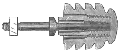
ONE form of this insulator (the design of Mr. A. R. Bennett, of Glasgow) is shown by figure 1. The invention was adopted by him about a year ago, in the construction of the telephonic lines of the National Telephone Company, Limited, by Messrs. D. and G. Graham, of Glasgow. Prior to the introduction of these insulators it had been the universal practice, in Great Britain, at all events, to insulate over-house telephonic wires by means of double-shackles, i.e., two shackle-cup insulators fastened to the pole or other support by means of four galvanized iron straps and three galvanized iron bolts and nuts. This was done owing to the desirability of confining the effects of a rupture of the wire to the span on which it occurred, and also of preventing the wire falling into the street in case of the breaking of an insulator. The wires were consequently terminated in the well-known manner round a Bright's shackle-cup at every support, and were joined through to the next spans by short cross-connections or jumpers. But the mechanical advantages of the shackle obtain to a great extent at the expense of the electrical. At each cup the current has two paths to earth, which, everything else being equal, would, by the law of derived circuits, reduce the insulating efficiency of the single-shackle to one-fourth of that of an upright insulator, and of the double-shackle to one-eighth. But in practice, especially in wet weather, the proportion in favour of the upright, even if only a single-shed, is very much increased, as the shackle has no inner cup, and no part of it can be kept even approximately dry. A good double-shed upright probably insulates thirty times better than the double-shackle, its large effective dry surface being wholly, in addition to the gain of eight times, derived from the position of the wire at its summit, and the existence of only one path to the bolt. Mr. Bennett's attention was directed to the bad insulation of telephonic wires constructed on the old plan by the frequent occurrence of overhearing on comparatively short lines. This was popularly attributed to the effect of induction, but by substituting upright insulators for the double-shackles, the disturbance was either cured entirely or perceptibly diminished.
 |
| Fig. 1. |
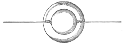
The so-called induction was, therefore, proved to have been, in part at least, actual current leakage. So far so good; but it would not do to use ordinary upright insulators for overhouse work. Something to fulfil the mechanical function of the shackle was required, so Mr. Bennett designed, early in 1882, the form of insulator shown by fig. 1. and also a similar form without the inner cup. They are used in precisely the same way as shackles, each span being terminated round the insulator, and joined through to the next by a soldered cross-connection (fig. 2). When light wire, such as Nos. 16 to 20 phosphor bronze, is employed, both spans are terminated round the topmost corrugation.
 |
| Fig. 2. |
With heavier wire it is better to terminate each span in different corrugations, preferably the first and second from the top. When unusually long spans are necessary it is well to reduce leverage by using the second and third, or even the third and fourth corrugations, the insulation under these circumstances, owing to the dry cup, still being far superior to anything obtainable from shackles. The terminating of the wires round the lower corrugations is also advisable when a support happens to be placed much below the level of those on each side of it. The breakage of a span does not consequently affect the neighbouring ones, while the extension of the bolt into the head of the insulator prevents the fall of the wire into the street when an insulator breaks. Besides admitting of the spans being terminated, the four corrugations increase the insulating surface considerably, and give the insulator a very ornamental appearance. The single-shed is intended for use on wires of moderate length. The double-shed shown in the figure possesses a high insulating efficiency, is very substantial, and is well adapted for long telegraph lines and for carrying heavy electric-lighting conductors.
