[Trade Journal]
Publication: Electrical Industries
Chicago, IL, United States
vol. 4, no. 9, p. 270
The Underground System at the World's Fair.
As the visitor approaches the World's Fair at night he sees every part of the grounds lighted and as he watches the brilliant effect he is too much absorbed in the scene to think of the means employed to distribute the thousands of electrical horse power used over so large an area. As he walks about the grounds he notices the ornamental lamp posts standing out neatly, unencumbered by any overhead wires and with no visible communication with any source of power. In Electricity Building he sees hundreds of horse power of machinery and lights operated by the same force. In the Manufacturers and Liberal Arts Building he rides to the roof 250 feet above the floor in an elevator raised by this same force.
For the distribution of the electricity for lighting, power, telephone, fire alarms and telegraph systems plans were considered early in the preparation for the Fair and the large subway that reaches from Machinery Hall annex to the Fisheries Building with the various branches and connecting ducts was constructed. The visitor walks through
 |
FIG. 1. — THE UNDERGROUND SYSTEM AT THE WORLD'S FAIR.
the Government Building through the west side of the Manufactures and Liberal Arts Building, across the plaza in front of the Government Building, quite unconscious of the sub-way beneath him, carrying power and light to the buildings and grounds or of the workmen who in the ground under him are inspecting the many lines of cables in this underground passage way. To the visitor of a practical turn of mind, a visit to this giant subway will be of interest as it is one of the great engineering features of the Fair.
In its construction a number of things were necessarily considered; its size, strength, ventilation, drainage, protection from fire, and also its temporary character, while in planning its course through the ground many difficulties were met with incident to the character of the soil and the crossing of other systems of distribution.
The subway is built of plank two inches in thickness spiked to three by eight inch timbers set 12 inches apart. Over the inner edges of these timbers is fastened expanded metal lathing which is covered with cement offering an incombustible surface on the inside. The main sections of
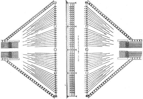 |
FIG. 2. — THE UNDERGROUND SYSTEM AT THE WORLD'S FAIR.
the subway are six feet six inches square. From Machinery Hall to Electricity Building the sub-way is double. From the Electricity Building a branch extends to the Mining Building while the main line of sub-way runs east toward the Manufactures and Liberal Arts Building. It passes then under the Manufactures and Liberal Arts Building on under the Government Building to the Fisheries Building
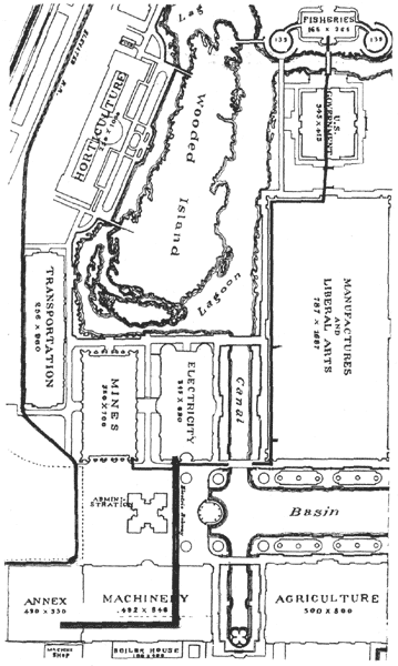 |
FIG. 3. — MAP SHOWING COURSE OF SUBWAY.
in a course as illustrated by the heavy black lines shown on the map Fig. 3. As the cables stop at the various buildings or are run off to the various parts of the grounds along its course the subway is gradually reduced in size toward the north end.
The top of the subway is but a short distance below the surface of the ground, about 20 inches on an average. It
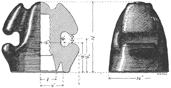 |
FIG. 4. — THE PIERCE INSULATOR.
is entered through trap doors in the floors of the buildings and through manholes on the ground. One of the problems that the engineer encountered was the crossing of the lagoon and the plan adopted which is illustrated in the accompanying cuts, Figs. 1 and 2, shows the ingenuity displayed in meeting this problem. The subway widens as it approaches the lagoon and the wires are spread out and suspended from the under side of the bridges which cross the lagoons at those points. The subways are open these ends for ventilation.
The method employed of running the wires holds them firmly in place and also permits easy access to any and all wires. About every thirty feet along the walls are iron frames in which are sockets for supporting the oak cross arms. Each arm holds five pins on which are screwed double Pierce insulators of the design shown in Fig. 4
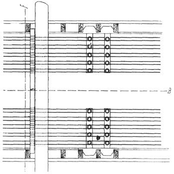 |
FIG. 5. — PLAN SHOWING POSITION OF WIRES AND PASSAGEWAY.
There are 12 cross arms on each side between which is the passage way for the inspector and workmen. Each section of the tunnel will hold 240 cables when of full size. At its smaller end near the Fisheries there are in place but 20 insulators. The total length of single subway is 6,915 feet. From Machinery Hall to Electricity Building the subway is double a distance of about 1,000 feet. It is well drained and the 16-candle power lamps which run 5 in
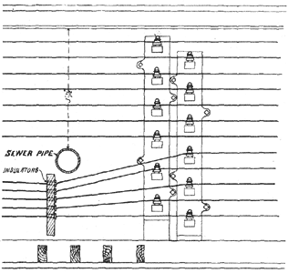 |
FIG. 6. — ELEVATION SHOWING WIRES.
series from 500 volt mains furnish abundant workmen.
From printed cards showing a cross section of wires the circuits are easily found. The power, incandescent and arc circuits are grouped separately. The telephone and fire alarm cables are separately attached to the wall. For conveying the cables from the subway to the different parts of the grounds where the electricity is to be utilized pump logs are laid; except where the wires enter the buildings where vitrified soil pipe is used. For carrying the wires from one lamp post to another, ducts or pump logs
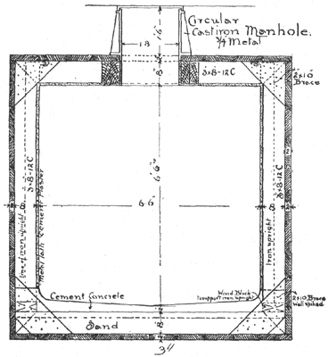 |
FIG. 7. — THE UNDERGROUND SYSTEM — CROSS SECTION OF SUBWAY.
are used which have recently fulfilled their object very well, although early in the spring considerable trouble was had with them.
