[Trade Journal]
Publication: Western Electrician
Chicago, IL, United States
vol. 9, no. 22, p. 317, col. 1-3
Electric Subways for the World's Fair.
Attentive readers of the WESTERN ELECTRICIAN must have been before this impressed with the fact that an immense amount of electricity is to be transmitted from the great service plant at the World's Fair to various parts of the grounds for light and power. Overhead wires are, of course, out of the question, and subways were long ago decided upon as the only feasible means of meeting the conditions. For several months Electrical Engineer Sargent has been at work on the plans for the subway system, with a large force of draughtsmen to put his ideas on paper, and at last week's meeting of the committee on electricity his designs were formally adopted. It has been no easy task to devise a plan adequate to meet the requirements as to size and efficiency without involving a construction too complex and expensive for temporary use. Several designs were considered, but were, one after the other, found open to objection, until the present plan was evolved.
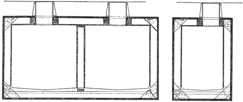 |
| Figs. 2 and 3. Electrical Subways for the World's Fair |
A general idea of the system may be had by a reference to the accompanying map and drawings. The generating plant, as indicated, will be located in a portion of machinery hall set aside for its use. This space will be 850 feet long by 150 feet wide, and in it it is expected that 25,000 horse power will be generated. The engines will be located near the wall, and the dynamos toward the center of the building. The conductors, after leaving the dynamos, will be arranged in a suitable fire-proof rack located under the main floor about 150 feet from the south wall, and running lengthwise of the building. From the rack five distinct groups of feeding wires will start as follows: The first group will supply all the territory contained in the space bounded by Fifty ninth street on the north, the center of the basin on the south. Lake Michigan on the east, and the lagoon on the west; also the electric fountain located at the west extremity of the basin, and the following buildings, etc.: The fisheries building, the government building, the naval exhibit, the manufactures and liberal arts building, and all the grounds within the territory. It is proposed to provide a main conduit for this group in the following manner: Starting from the rack in machinery hall already referred to, a conduit is to be provided; this conduit is to be of sufficient capacity to accommodate 150 insulated cables of various sizes up to 600,000 circular mils area. The conduit will run north from the rack under the floor of the machinery hall to the electricity building, with a branch for the electric fountain; east from the electricity building to the bridge, and from the bridge to the manufactures building. The system will terminate at the fisheries building. The tunnel itself, or any of the buildings through which it passes, maybe tapped by draw-in systems buried in the ground wherever it is necessary to supply light or power to the grounds or any other buildings that may be erected in this territory.
 |
| Fig. 4. Electrical Subways for the World's Fair. |
Group No. 2 will be provided for in a conduit of the same capacity as that for the first group, and will run direct from machinery hall to the electricity and mines buildings, with a branch for the administration building. This will also provide for all grounds adjacent to these buildings, and will probably include the wooded island.
Group No, 3 will run direct from the machinery hall to the elevated railroad structure, and supply all territory north of the basin and the administration building not reached by groups No. 1 and No. 2, including the transportation building and annex, the service building, the horticultural building, the woman's building, the state and foreign building, the art gallery, the Midway Plaisance, and all grounds and smaller buildings in the territory mentioned. Draw-in systems or buried conductors are to be used wherever the elevated structure is not available.
Group No. 4 will provide for the machinery hall, the machinery annex, the boiler house, the western portion of the stock exhibit, and the western portion of grounds. The wires will be distributed under the basement of buildings and on elevated railway, beneath the track, and thence to the grounds and stock exhibit by draw-in or buried systems.
Group No. 5 will provide for the agricultural building and annex, the sawmill, the forestry building, the dairy building, the eastern portion of stock exhibit, and the pier and casino.
The wires are to be distributed on the elevated structure, in the basement of the agricultural building, and on piles under the roadway over the pier so far as practicable, and then by draw-in or buried systems. The tunnel system cannot be well continued farther north than the fisheries building, because the ground is not of sufficient height above water-line. Groups No. l and 2 will be laid in the conduits, which are indicated on the map. Fig. 1, while the others are provided for in the manner described.
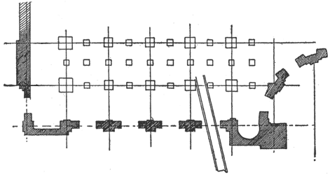
The three smaller drawings show details of the construction of the conduits. In Fig. 2 is shown a section of the double conduit extending from the generating station to a point north of the administration building. This is enclosed in one wooden structure, and comprises two full sized conduits. Those parts of the conduit north of the center of the manufactures building and leading into the electricity and mines buildings are of a smaller size, shown in cross section in Fig. 3. A ground plan of a corner of the electricity building is presented in Fig. 4, showing the manner of laying the conduit among the foundation timbers.
The greater portion of the conduit will be exactly eight feet and four inches square. The outer material will be two-inch tarred plank laid on stringers one foot apart. These stringers will be eight inches wide and they will support the inner skin of the conduit, which will be an inch thickness of cement plaster laid on metal lathing. The larger tunnels will be six feet six inches wide inside, and the smaller size four feet three inches. All will be six feet six inches high in the clear, so that a man may walk through without difficulty. In the larger conduits there will be a passageway in the center, with a row of cross arms on either side, while in the smaller ones there will be but one row of cross-arms, with a side passage way. Man-holes, shown in Figs. 2 and 3, will be provided at convenient distances. The cross-arms will be supported on iron castings especially designed for the purpose, which will be placed twenty feet apart, and bolted to the stringers. Glass insulators of a size sufficient to accommodate the largest cables will be used on the cross-arms. All wires must be covered with water-proof insulation. The conduits will be laid, on an average, eighteen inches below the surface of the ground, and will at all times be above the level of the lake. The interior will have the appearance of a concrete tunnel, and there will be ample room for all the wires necessary. The World's Colombian Exposition will furnish the conduits, cross-arms and insulators, but contractors for lighting or power service will be required to furnish wires and place them in position. It is expected that the contract for the wooden work of the conduits will be awarded in about two weeks.
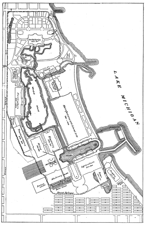 |
| Fig 1. Electrical Subways for the World's Fair. |
