[Trade Journal]
Publication: Cassier's Magazine
New York, NY, United States
vol. 8, no. 3, p. 333-362, col. 1-2
DISTRIBUTION OF THE ELECTRICAL ENERGY FROM
NIAGARA FALLS.
By S. Dana Greene, Electrical Engineer.
THE utilization of at least a portion of the enormous amount of energy which, in the parlance of this practical age, runs to waste annually over the Falls of Niagara, has been written and talked of, studied and suggested, for the past hundred years. It has been re served, however, for those of us who will see the nineteenth century rounded out and the twentieth ushered in, to witness the practical accomplishment of this great undertaking.
| |||
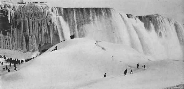
| Winter at the Falls. |
Other articles in this magazine tell of the engineering skill, perseverance and ingenuity which, combined, have helped to bring about the harnessing of Niagara. It is the purpose of this article to point out some of the applications to which the electric energy generated at the Falls has already been put, and to discuss other applications which suggest themselves as probabilities or possibilities. These applications can be broadly divided into two classes: (1) Those which are undertaken near the generating station, within a radius of, say, ten miles. (2) Those which necessitate a transmission of the power for a distance of more than ten miles before it is utilized.
| |||
| The Electric Plant of the Pittsburg Reduction Company of Niagara. |
The first class offers a tempting field to those practical men who prefer present certainties to future possibilities; while the second class presents an array of scientific problems, and of theoretical and empirical studies and calculations which are attracting attention of the whole engineering world. Time alone can tell how many of these problems will be solved, and how far practical results will verify the theoretical figures. We may, however, assume with reason able certainty, that as the science of electricity, which is yet young, advances from year to year, the area of influence of the Niagara power will be constantly extended, until that historic and picturesque spot becomes a true electrical Mecca. When this result shall have been accomplished, the farseeing business sagacity and engineering talent of those who have launched the present enterprise will bear their fruit, while the capitalists who have boldly invested their millions will have their proper reward in a handsome and ever-increasing return on their investment.
Before discussing in detail the two classes of application already mentioned, it is well to glance at some of the broader questions involved. The electric motor is already well-known as a piece of commercial apparatus. Thousands of them are in daily use, having displaced steam and gas engines and other forms of power motors. It is compact, easily cared for, very reliable, and, with a continuous rotary motion, it can be applied to its work with a minimum of expense and complication. For reliability, simplicity and certainty of operation, it stands without a peer in the motor field. It follows, as a matter of business, that industrial power consumers can, with profit, substitute the electric motor for that which they now use, provided the electric power can be delivered to the motor at a cost less than that now paid for other power, including the cost of operating and maintaining the motor.
Such a change of motive power has been, as a matter of fact, progressing actively for the past five years, especially in the larger cities, where a network of wires, either overhead or underground, has gradually covered the territory like a system of gas or water pipes, ready to be tapped for any consumer who desires to use the electric power. The extent to which the change has been effected is not generally realized. Thus in New York, it is estimated that not less than 8000 horse-power in electric motors are at present in use, the motors varying in size from horse-power to 100 horse-power; in Brooklyn about 4000 horse-power are employed, while 25,000 horse-power additional in motors are used in that city for electric traction purposes.
In many large industrial manufacturing establishments it has been found economical to generate electric power in a central power station, and then distribute it throughout the various shops, electric motors being utilized to operate the lines of shafting, heavy tools, cranes, rolling mills, etc. In all of these applications, the reason for the change in power is found, first, in the ease and economy with which the electric power can be transmitted; and, second, in the high efficiency and low cost of maintenance of the electric motor. Although additional conversions of energy are involved, these con versions are accomplished in large units, under the most economical conditions, so that there is an actual and very important saving to an establishment using electric power throughout, instead of steam, or compressed air, or rope transmission.
| |||
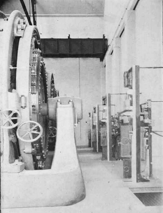
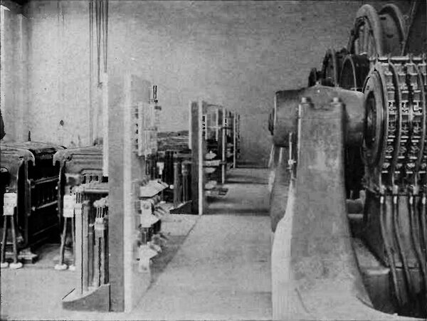
| Direct-Current Side of the Rotarty Converters of the Low-Tension Switchboards. |
| |||
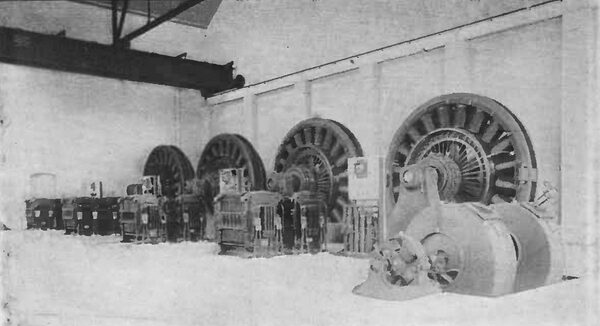
| Two of the Rotary Converters and Also Two of the Static Transformers in the Pittsburgh Reduction Company S Plant. |
In addition, electricity has a large, and ever widening field in lighting, heating and cooking; in plating and electrotyping; in the smelting and reduction of refractory ores; and in surgical and medical work. It is, in fact, becoming more and more a part and parcel of our every-day practical requirements, while in the language of the patent office, "new and useful applications are in daily process of invention and development.
With such a field of usefulness for electric power, and with the assurance of the best technical advice attainable that the work was feasible from an engineering standpoint, and that the cost was not at all prohibitive, one can realize why it has been possible to secure capital for the Niagara power plant; and as the present power house stands ready to deliver fifteen thousand horse-power in electrical energy, with an ultimate capacity of fifty thousand horse-power (the intake canal being large enough to supply two power houses of this capacity), we can consider the nearby applications of power about to be made.
The Niagara Falls Power Company owns somewhat more than a square mile of land around the power house, and it purposes to rent or sell this land to industrial establishments desiring to locate there, and to sell them electrical power, available for twenty-four hours a day, every day in the year, at a price so low that these establishments can afford to move from their present locations and sell their present plants.
The power, as generated, is an alternating two-phase current of twenty five cycles per second, or three thousand alternations per minute, the electro motive force, or electrical pressure, being about two thousand volts. At this voltage, and with the short distances involved in local distribution, the transmission involves no engineering difficulties, electrical or otherwise; in fact, it is similar to many such transmissions in various cities and towns. Many inquiries have been received from all parts of the country asking for information as to the character and cost of the power service, the amount of power available, etc. Two manufacturing establishments have already closed contracts, erected new plants on the ground, and are about ready to start operations, viz.: the Pittsburgh Reduction Company, of Pittsburgh, manufacturers of aluminum, requiring 2000 horse-power; and the Carborundum Company, also of Pittsburgh, manufacturers of carborundum, a variety of emery, requiring 1000 horse-power. As each of these companies will utilize the electric current for a special purpose, each differing entirely from the other, a brief description of the two plants will be of interest.
The Pittsburgh Reduction Company produces pure aluminum, a metal which is beginning to attract favourable attention from alumina, an oxide of aluminum, by smelting the latter with the proper flux, in carbon-lined retorts or crucibles, the mass being liquefied and the aluminum reduced by an electric current, passing from a series of carbon rods suspended over the top of the crucible and forming one pole of the circuit, to the carbon lining at the bottom of the crucible which forms the other pole. The current required is what is commonly called a direct current, the voltage, or pressure, at the terminals in the reducing room being maintained constant at 160 volts, and about 60 retorts being placed around the room in series with one another.
| |||
| The Alternating Current Side of the Rotary Converters, the Alternating Current Switchboards and the Static Transformers. |
| |||
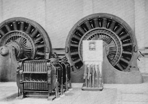
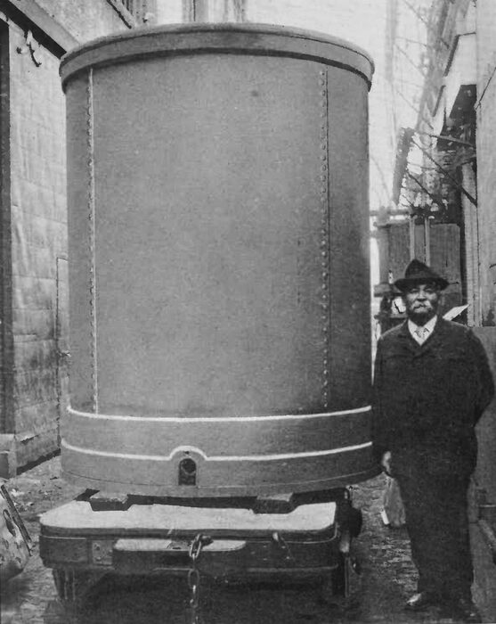
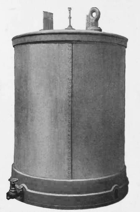
| One Thousand Horse-Power Static Transformer at the Works of the Carborundum Company. Built by the General Electric Co. New York. |
| |||
| Another View of the Static Transformer. |
As the current, delivered to the Pittsburgh Reduction Company by the power company, is of the two-phase variety, alternating, at 2000 volts pressure, it is necessary to reduce this pressure and then transform the current from alternating to direct. The first change is accomplished by passing the current through large static transformers, built on the principle of the Rhumkorff coil, by which the voltage is reduced from 2000 to 115. The current is then passed through a rotary converter, where it is changed from a two-phase alternating current at 115 volts to a direct, or continuous, current at 160 volts. The rotary converter is a direct-current generator, with the addition of proper collecting rings and connections on the rear of the armature, by which the alternating current is led into the machine. It may be considered, in fact, as a motor and generator in one machine. The illustrations on pages 334 to 337 show the power room of the Pittsburgh Reduction Companys plant, with the apparatus installed and ready to operate. The plant has a capacity, on the direct current side, of 10,000 amperes at 160 volts, or 1600 kilowatts, or about 2000 electrical horse-power.
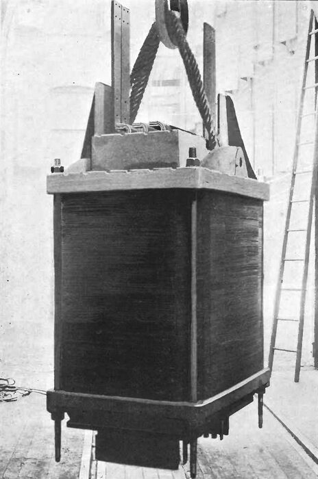
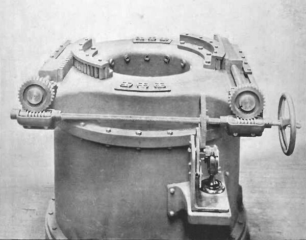
The Carborundum Company utilizes electricity in a different way. A large core of carbon, about 8 feet high and a square foot in cross section, is placed vertically in a large smelting furnace, and around this core is packed the carborundum ore. An alternating electric current is then passed through the core from end to end, the core being gradually brought to an intense (white) heat. This heat is kept up for about twelve hours, the carborundum being gradually reduced from the ore, in crystalline form. The crystals are taken from the furnace, ground to a powder and pressed and moulded in various forms for use as emery. The Carborundum plant consists of a 1000 horse-power static transformer, by which the voltage is reduced from 2000 to 100 and 200 volts, and a special regulator of about the same size, by which the voltage at the core of the furnace is varied as the resistance of the core changes, owing to its change of temperature, the current being maintained about constant. The illustrations on pages 338 to 341 and on page 348, show this apparatus in completed form. The Carborundum plant is unique, both on account of the way in which the electric power is utilized and also on account of the size of the static transformer and regulator, which are the largest pieces of apparatus of the kind ever built.
Static transformers of the size used in these two installations (270 horse-power and 1000 horse-power respectively) require some artificial method of cooling, for, notwithstanding the fact that the transformers have an efficiency of from 97 to 98 per cent., the energy transformed into heat is, nevertheless, so great that there is not sufficient radiating surface to carry it off, and the temperature at full load would soon rise to such a point as to endanger, if not destroy, the apparatus. Two different plans of cooling have been adopted. In the Pittsburgh reduction transformers a blast of air is forced constantly through the numerous interstices between the coils, from below, and the heat is thus easily controlled.
| |||
| The Internal Make-Up of the Carborundum Co.'s Large Static Transformer. This Transformer Reduces the Pressure of the Two-Phase Alternating Current From 24oo to 2oo Volts. |
The Carborundum transformer is cooled by a continuous circulation of oil. The transformer is placed in a cylindrical iron case, standing on a ring about 6 inches high from the bot tom of the case. Oil is forced into the transformer from the bottom, and up through its interstices, until it flows over the top and into the surrounding case. It is then drawn off, passed through a cooling coil surrounded by running water and is again forced through the transformer. The resulting decrease in the temperature rise is the same as in the case of the air blast. In either case the amount of power required for the air blast or for the oil circulation is very small less than ½ per cent, of the capacity of the transformer.
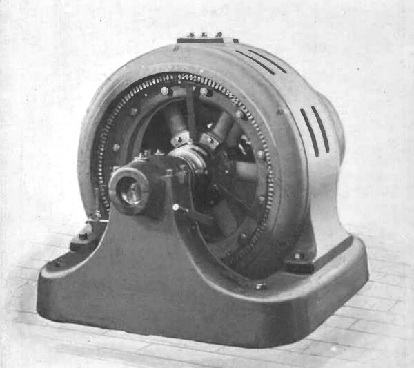
Another application about to be made of the power is the operation of the electric road at Niagara Falls, and also of that now being pushed to completion, as a rapid transit line, between Buffalo and the Falls. About 1500 horse-power in rotary converters will be required for this work, in 500 horse-power units, transforming the alternating into direct or continuous current at 500 volts. The electric lighting station and the water works at the Falls will probably also utilize the power at an early date. With nearly 5000 horse-power contracted for locally, and with the probable demands in the near future for other new plants, as well as for extensions to those already installed, it is reasonably certain that from 10,000 to 15,000 horse-power will be required in a year to supply the demands of consumers within a radius of three miles of the power station. Between Niagara Falls and Tonawanda a distance of about ten miles is an open, farming country, which is already being bought up for the purpose of cutting it up for manufacturing sites. Tonawanda itself, which may be considered within the radius of what has been classed as "near-by distribution," has special advantages as a manufacturing centre.
| |||
| The Corborundum Company's One Thousand Horse-Power Current Regulator. |
Ten thousand additional horse-power is a reasonable estimate of the power that will be utilized in this territory, so that it seems fair to predict that in five years, with moderately prosperous business conditions, the "near-by" consumers of power will aggregate about 25,000 horse-power. This power will be distributed and used on tin general lines already developed in other places, except that the individual consumers will be larger users. No radically new electrical engineering problems are involved, and the cost of distribution will be relatively small. The consumers will reap the benefit of very cheap power, available at any hour, day or night, while the Power Company will be assured of a definite revenue, without the large expenditure necessary for heavy transmission lines and their accessories.
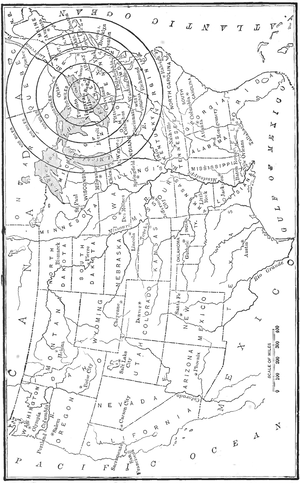 |
| Map of the United States, Showing the Commercial Possibilities of Niagara Power. |
| |||
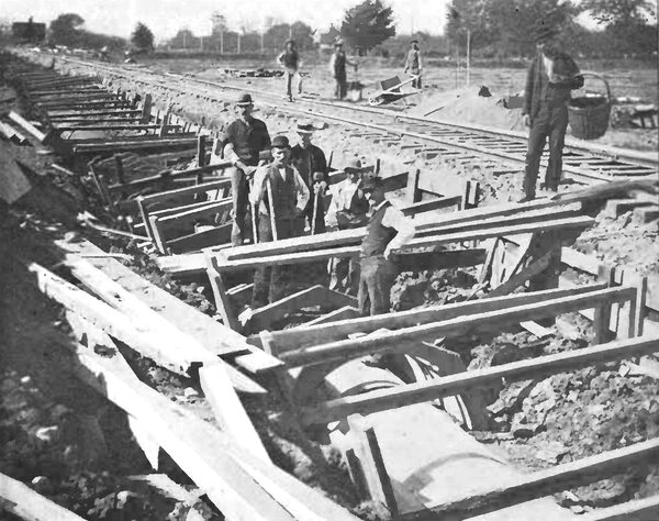
| Putting Down Cable Conduits at Niagara. |
The applications of power thus far suggested or discussed are such as come substantially within the present stage of electrical development, and have little about them, therefore, to cause distrust of their successful outcome, financially or otherwise, even in the minds of those who have given no special attention either to the rapid growth of the electrical art in general or to the development of this great power plant in particular.
We come now to the second and larger phase of the subject the transmission of the power from Niagara to Buffalo and points beyond, where, in order that its sale may be rendered the more profitable by reason of the quality consumed, it must successfully dis place existing power plants of all descriptions, including even the local electric lighting and railway plants at present operated by steam, and must establish and prove its claim of superior economy and of equal or superior re liability and continuity of service. It is the solution of this problem that demands the attention of electrical engineers, and the results will determine whether the present power house at Niagara, with its ultimate capacity of 50,000 horse-power, shall be only the beginning or the end of the enterprise. It is instructive to study the map and consider the geographical and commercial possibilities of different areas of distribution, with Niagara as a centre. From this point, on the map shown opposite this page, circles have been drawn with radii of 100, 200, 300, 400 and 500 miles. Table I. gives interesting data of several areas so circumscribed, including areas with the smaller radii of 25, 50 and 75 miles.
|
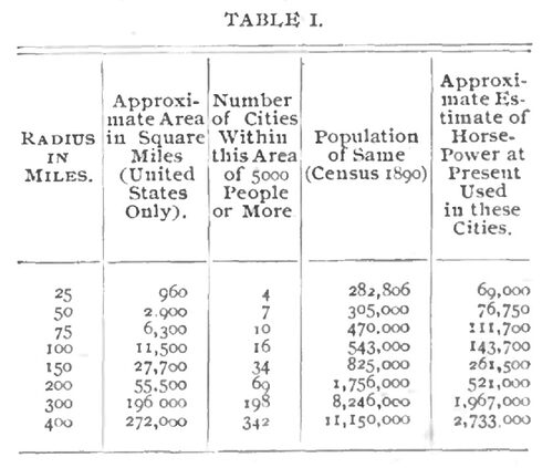
About one-fifth of the population of the United States is included within a radius of 400 miles from Niagara. The conditions controlling the commercial delivery of power to a point within any of the areas given depend upon the answers to the following questions:
1. What amount of power can be sold, provided it is delivered? That is, what are the local demands?
2. Are the transmission and delivery to the desired points practicable from an engineering standpoint?
3. If the power can be delivered successfully, can it be sold by the Power Company at such a figure as to compete with the price of power generated locally; that is, compete with the large and economical local power plants, such as electric light and railway stations and city water works, as well as with the small and comparatively wasteful users?
|
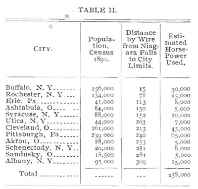
The latter class of power consumers are, of course, much more numerous in point of numbers, but not necessarily so in point of amount of power consumed throughout the twenty-four hours. The first question can be answered only by a local investigation and canvass of the power users, their present consumption and the probable annual growth of this consumption. This latter point is of importance, for the transmission line and transformer stations should be built so as to provide for reason able growth in demands for a period of from five to ten years. It should not be necessary to erect new buildings, nor to provide new pole lines or conduits for this growth; they should be built of such a capacity as to make it necessary only to install additional apparatus or additional cop per wire in the stations or on the pole lines originally provided. The following table gives an idea of the demands for power in some of the principal cities included in Table I. on page 343.
| |||
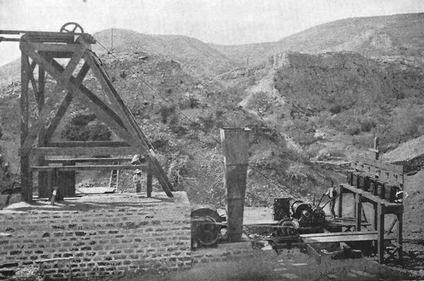
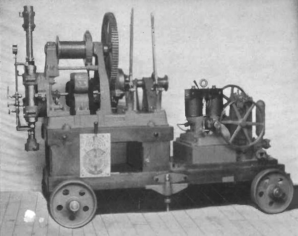
| An Electric Hoisting Plant at Boleto, Mexico. |
| |||
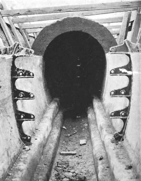
| Cross Section of A Cable Conduit. |
The second question, regarding the engineering possibilities, is a vital one, and demands careful consideration. Apart from engineering problems pure and simple, it is to be remembered that the transmission line to any of the points mentioned in Table I. must pass through a more or less populous country, and if the necessary voltage or pressure of the current is so high, or if the pole lines and conductors must be of such a size and so placed, that the insulation of the line cannot be maintained, or danger to human life cannot be avoided by any reasonable precaution, then the transmission cannot be considered practicable commercially.
Precedents are always of value in studying the solutions of engineering problems, and it is interesting to consider briefly two remarkable long-distance transmissions of power in successful operation in the United States, although neither are electric transmissions, and each differs materially from the other. One is the transmission of oil by pipe-line, from the natural oil fields of New York, Ohio and Pennsylvania, to tide-water, a distance of over 400 miles. The other is the transmission of natural gas, also by pipe-line, from the Indiana fields to the city of Chicago, a distance of about 120 miles.
The piping of oil, first from the individual oil wells to storage centres, and then from these storage centres to tide water, has been a process of gradual development for the last thirty years. The necessity for what may be called the "collecting system of pipes was felt shortly after the discovery of the natural oil wells, and arose from the rough and mountainous character of the oil country, which made the question of transportation an exceedingly difficult one. The individual wells were gradually connected by feed pipes to larger trunk lines, which carry the oil to the storage centres.
The largest of these centres is at Olean, N.Y., about seventy-five miles from Buffalo. There the Standard Oil Company have large storage tanks, with an aggregate capacity of nearly 9,000,000 barrels of oil, and from this point starts the great trunk line, composed of three 6-inch wrought iron pipes, running to tide-water in New York harbor, where the oil is loaded into tank steamers and shipped all over the world. There are twelve pumping stations along this trunk line, situated about 35 miles apart, and both the pumps, the pipe-lines and the subsidiary fittings are marvels of mechanical ingenuity and perfection. The pumps operate at a pressure of about 1000 pounds per square inch, and the capacity of the line is about 30,000 barrels a day.
The main pipe-line is divided into divisions and sections, much like a trunk railway system, and has, similarly, its division superintendents and engineers, section foremen, line gangs and line walkers, telegraph stations and daily reports. The system works smoothly and quietly, and as the pipes are buried under ground from one to two feet, and run through a sparsely settled country, the general public sees or hears but little of the system.
A trunk line runs from the Ohio fields to Chicago, another line has been projected from these fields to St. Louis, and two other lines run from West Virginia and Pennsylvania to Philadelphia and Baltimore. The object of the pipe lines is to cheapen the handling and transportation of oil to the great consumption centres of the country, and while there is no general distribution system at the point of delivery, the line, nevertheless, can properly be considered as a transmission of power on a large scale, where the difficulties of transmission are many and great.
The natural gas pipe line is, perhaps, a more simple example of long-distance power transmission, and bears many striking points of resemblance to transmission by electricity. The Indiana gas field covers a territory in the north ern part of the State, about 38 miles long and 18 miles wide. There are about 60 wells in operation, having an average daily capacity of about 5,000,000 cubic feet each. As in the oil fields, so here, the individual wells are connected by feed pipes to a supply line, which collects the gas and carries it to the pumping-station at Greentown. There large compressors, capable of producing and sustaining a pressure of 2000 pounds per square inch, force the gas into the transmission line to Chicago. The normal pressure carried on this line is 300 pounds per square inch, which admits of a daily delivery of 10,000,000 to 12,000,000 cubic feet of gas in Chicago.
| |||
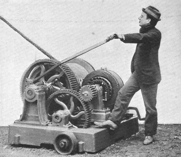
| An Alternating Current Induction Motor, Geared to A Hoist. |
| |||
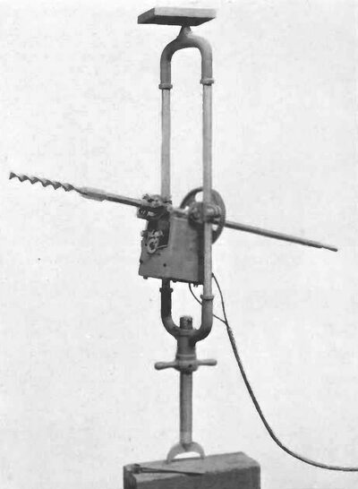
| An Electric Diamond Drill for Prospecting Work. |
| |||
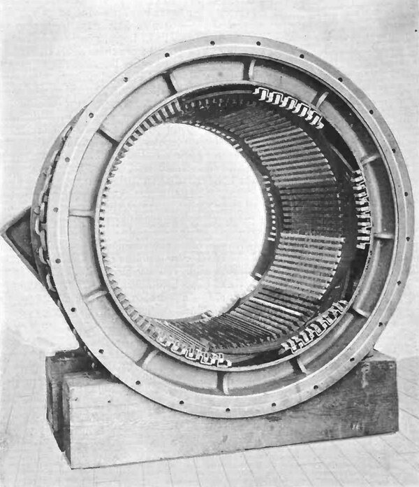
| Frame of the Large Regulator of the Carborundum Co. (See Page 339.) |
Along the line, which consists of two 8-inch wrought-iron pipes, laid 2-1/2 feet underground, are located what are known as "by-pass" stations, about 20 miles apart. At the "by-pass" either of the two main lines can be cut off and the gas sent through the other line. The stations are also utilized as headquarters for division superintendents, telegraph operators and repair gangs. At the Indiana State line the pressure is automatically reduced, in a "regulating station," to 40 pounds, at which pressure the gas is carried into the city by two 10-inch wrought-iron pipes. From these pipes it is fed into an extensive system of distributing mains, throughout the city, the pressure being again reduced to less than 1 pound per square inch. From the city mains the gas is delivered to individual customers for cooking, heating and operating gas engines, and for applying heat under steam boilers, at a price much cheaper than the ordinary illuminating gas.
We have here an example of a great natural force of nature, harnessed by man, carried to a distant point, and there distributed and sold for many purposes and to many customers, at a cost below that of the same force locally produced and distributed. The analogy between the commercial features of this transmission and that of the Niagara power (without reference to the means of transmission) is clear and striking, even to the non-professional man. The essential engineering features of the natural gas transmission are:
1. An initial station where the gas is collected from the wells and delivered to
2. A pumping station where the pressure is raised to a high point, measured by ordinary practice, in order to permit of the transmission of a large volume of the gas a great distance, with a reasonable and practicable size of transmission pipe and loss in transmission.
3. A duplicate transmission line, with stations every 20 miles, where a section of the pipe in use can be cut out for inspection or repairs, the station also serving as headquarters for those in charge of the section.
4. A line construction involving tin best material (much of it specially m.u and the most careful work of installation, in order to insure continuity of service and immunity from leaks, breaks or other accidents.
5. A "regulating station at the delivery end, where the high and dangerous transmission pressure is reduced to one that can be safely carried through the crowded streets of a great city.
6. A distribution system in the city by which the gas, transmitted wholesale, is distributed retail to individual consumers.
7. Finally, a complete and thorough organization for the care and preservation of the plant, including, especially, a continuous and minute inspection of the transmission line, with facilities at every " by-pass " station for instant repair; in short, every facility for the maintenance of the plant in a high state of efficiency and repair.
| |||
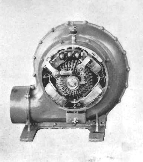
| An Electric Driven Blower. |
| |||
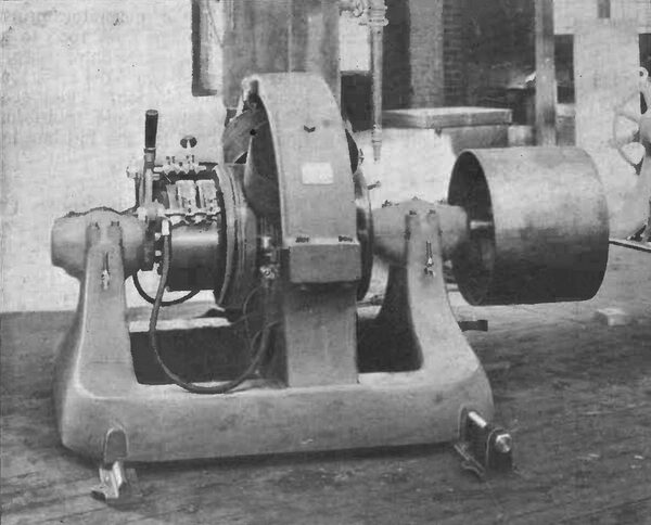
| A 250 Horse-Power Three-Phase Alternating Current Motor. |
As will be seen, the analogy between these salient engineering features and those which will distinguish the Niagara transmission is quite as marked as is the commercial analogy already noticed.
Returning now to the engineering problems of the Niagara transmission, the conductors can be carried either overhead, on a pole line of iron or wood, or a combination of iron and wood, or underground, through a subway, where cables are laid or hung in the subway, with a passageway for inspection, or in individual underground pipes or tubes. Where the conductors pass through a city, one or the other of the underground methods will, undoubtedly, be required, but for the main transmission line, across country, it is quite possible to construct an overhead line so substantial as to reduce to a small and unimportant factor the danger to the line from storms of wind, rain, snow or sleet, or from lightning. We have a practical example of such a line in the modern, long-distance, telephone trunk lines, which are the finest examples of line construction anywhere in the world, and some of which are more than 1000 miles in length.
The next important question is the size and insulation of copper conductors necessary. Practical considerations limit the size of a wire for good overhead construction to one having a cross sectional area of something less than 1/2 square inch; and if a greater area be necessary, it is divided among two or more conductors. The area of conductor necessary to transmit a given amount of electric power a given distance may be expressed by the equation:
A (area in square inch) = (C x N x D) / (E x V)
In this C represents a numerical constant; N the number of electrical horse-power to be delivered; D the length of transmission line, in feet; E the electromotive force (or pressure) at the delivery end of the line; and V the loss of pressure in volts on the line, due to its resistance.
This equation applies strictly to direct currents, and while the transmission of alternating currents involves certain other losses and disturbances between conductors, they need not be here considered, since they can be practically neglected by a proper arrangement of the conductors in a system such as is here contemplated.
| |||
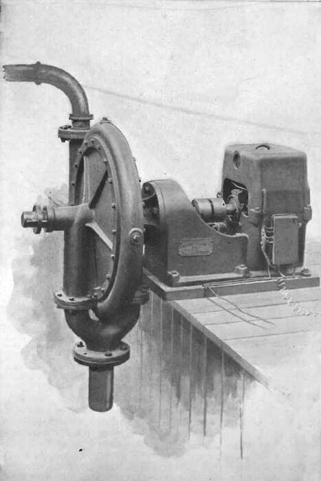
| Centrifugal Pump With Direct-Connected Motor. |
In non-technical language the equation means that the area of conductor, and, hence its weight and cost, varies directly as the horse-power delivered and distance transmitted, and inversely as the electrical pressure at the delivery end of the line and loss of pressure in the line. It follows that the higher we make the delivery, and subsequently the initial pressure, the smaller and less costly becomes the conductors. The similarity to the laws governing a similar transmission of a liquid, or gas, is noticeable. In the latter case the limit of pressure carried is the strength of the pipeline and joints; with electricity the limit is the insulation resistance of the conductors. For high pressures, 10,000 volts or more, on an aerial line, insulation material on the outside of a wire cannot be depended upon, for, apart from the fact that it has not a sufficiently high inherent resistance to penetration, the weather soon deteriorates the insulation material, thus lowering its resistance to such a point as to render the insulation practically useless.
| |||
| Special Porcelain \"Double-Petticoated Insulator for High-Tension Transmission Lines. |
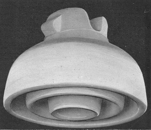
The safest and best plan is to use bare conductors, depending upon the supports at the poles for proper insulation. These supports are heavy, "double-petticoated" porcelain insulators, as shown on this page, mounted on the wooden cross-arms of the pole, like the ordinary glass insulators of a telegraph line. Such insulators have successfully withstood a pressure of 90,000 volts before puncture. In such a test, however, actual conditions of weather and atmosphere cannot be fully reproduced, and a safety factor of two is not too large to allow. These insulators are sometimes made in two parts, separated by oil. It is very difficult, however, to keep the oil perfectly clean, and the best practice to-day is to use air separation, which, under conditions of service, is probably more reliable than a separation by oil.
The following list of the principal transmission plants installed or in process of installation elsewhere is interesting as showing what has already been done up to date:
|
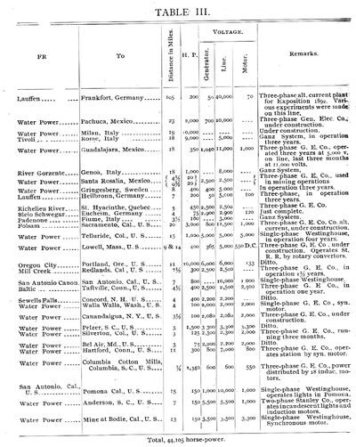
The plant which at once attracts attention in Table III is the Lauffen-Frankfort transmission of 200 horse-power over a distance of more than 100 miles, and at a maximum line pressure of over 40,000 volts (this in 1892). While it is true that this transmission was on a small scale, comparatively, and while it was more or less experimental in character, it is none the less significant and suggestive of what can probably be done to-day on a large scale with the wider experience and improved methods and apparatus of today. The next highest pressure is that on the Guadalajara line, where 11,000 volts are successfully employed. The conductors of the Lauffen-Frankfort line were bare copper overhead wires, attached to oil insulators on the poles, similar to those already described.
For the transmission of the first 10,000 horse-power to Buffalo from Niagara Falls, it has been practically decided to use 10,000 volts at the delivery end. Connections will be arranged at each end, so that this pressure can be increased to 20,000 volts, if desired. For points beyond Buffalo, it will, undoubtedly, be necessary to raise the delivery pressure still higher, in order to keep the cost of conductors within practicable limits, and for distances of 200 miles or more, the maximum Lauffen-Frankfort pressure of 40,000 volts must be equaled or exceeded. As the increase in the use of Niagara power, however, will necessarily be gradual, the pressure used, and hence the limiting distance of transmission, can be increased as rapidly as experience with lines already installed demonstrates that it is feasible and economical to do so.
Having determined the delivery volt age to be used, the only undetermined factor in the equation fixing the area of conductors, and hence their weight and cost, is the loss of pressure in volts on the line. Obviously we can reduce this loss indefinitely by increasing the area of conductors, but this increase can be carried too far, and the economical point is where the annual charges for interest, depreciation and repairs on the whole line (conductors, pole line and labour of construction) equals the money value of the power lost in transmission. This is known as Kelvins law, and applies strictly where the total line cost increases directly as the increase in area and weight of conductors. This is not usually the case in practice, since the pole line is built with a capacity for additional wires, and the cost of conductors is therefore usually so proportioned that the interest on any additional expenditure for copper will not be offset by the money value of the power saved.
| |||
| A Direct Current Electric Motor, Geared to A Pump. |
It is not practicable at the present time to build either generators or motors which will stand safely the high pressures of transmission here contemplated. It is, therefore, necessary to "step-up" the generator pressure, which may range from 1000 to 5000 volts, to the transmission pressure, and then to step-down the latter for de livery and distribution. This is accomplished by large static transformers, similar to those for the Pittsburgh Reduction and Carborundum plants, already described, arranged in units of from l000 to 2000 horse-power each, in "step-up" and "step-down" stations at each end of the line. The "step-up" and "step-down" stations correspond to the pumping and regulating station at each end of the natural gas pipeline.
The use of transformers makes it necessary to use the alternating current for long-distance work, and technical questions of current phase and frequency are involved in the engineering problem. A. discussion of such questions, however, involves a high technical knowledge, and as their proper relations and proportions are now well understood by technical men, it is not necessary to attempt to discuss them in a paper of this kind.
| |||
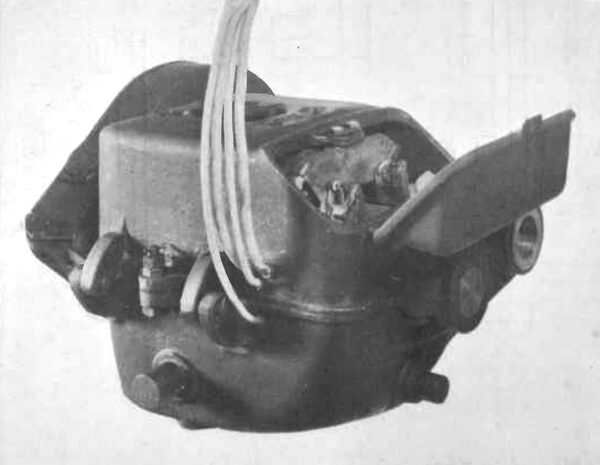
| An Electric Rotary Coal Drill. |
It is probable that duplicate pole lines and conductors will be installed for any long distance Niagara transmission, and for distances greater than 50 miles, one or more cut-out stations along the line will be advisable. The conductors will be led into these stations, and connections will be so arranged that any circuit, or any wire of a circuit, can be cut out for repairs or tests, and the current switched to another circuit. The stations will also serve as headquarters for telegraph operators, division foremen, repair gangs and line-walkers.
The work of a power transmission company ends properly with the de livery of the power, at low pressure, in the "step-down" station. Its local distribution and sale are similar to those of power generated locally, and should be handled by a local company familiar with the people and with local affairs generally. Such companies have already been organized in Buffalo and Syracuse, and will, doubtless, be formed in other cities to which the Niagara power may eventually be delivered. The local engineering problems involved are such as have already been met and solved in central station practice, and need not, therefore, be discussed now.
| |||
| A Modern Direct Current, Slow Speed Electric Motor. |
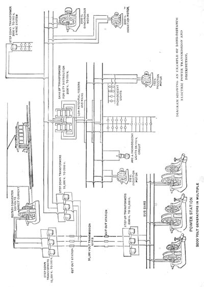
The illustration on page 358 shows, diagrammatically, the connections of a long-distance transmission such as that to be installed from Niagara to points sixty miles or more distant. Its distinguishing engineering features, and those which will mark a departure from anything heretofore attempted, are: The size of the units (generators, motors and transformers); the solidity and strength of line construction, and the electromotive force, or electrical pressure used on the line. The last feature is the only one that presents any unknown quantities, and it is really the one which will determine the engineering limit of the distance over which it will be possible to transmit a given amount of power from Niagara.
From experiments and tests already made on the Lauffen-Frankfort line, and elsewhere, it does not seem hazardous to predict that a maximum pressure of 50,000 volts at the delivery end of the line will be successfully adopted for long distances, if business conditions warrant the transmission. It is interesting to observe that in the transmission of either oil, gas or electricity, the limiting engineering condition is, in each case, the line pressure that can be safely carried.
| |||
| A Typical Electric Street Car Motor. 25 Horse-Power. |
| |||
| Diagram Showing An Example of Long-Distance Electric Power Transmission and Distribution. |
One other engineering feature should be mentioned, and that is the efficiency of the apparatus and transmission line. The transformation of energy by electrical apparatus is accomplished with a very small loss, and the efficiency increases with the size of unit employed. For generators, transformers and motors of l000 horse-power size, or larger, commercial efficiencies, that is the ratio of power delivered to power received, of from 97 to 98 per cent, at full load can be maintained; and as the load varies in a large plant, it will always be possible to keep the units that are in actual operation on full load duty, so as to realize the highest efficiency. The line efficiency
(ratio = Power delivered to step-down transformers / Power received from step-up transform)
will vary with the distance and the pressure on the line. For the most economical conductor cost, the line efficiency will vary, probably, in practice, from 92 per cent, for a Buffalo delivery of, say, 10,000 horse-power, at 10,000 volts (distance 15 miles), to something less than 60 per cent, for an Albany delivery of the same amount of power, at 50,000 volts (distance about 310 miles).
The third, and last question for consideration is the cost of Niagara power, delivered at various distances, as compared with the cost of power produced locally; and as steam power is now generally used, either for application to mechanical work direct, or else for driving electric generators, the question is, really, the cost of Niagara electric power, delivered in bulk, versus cost of local steam power. It goes without saying that if a city, as, for example, Rochester, is fortunate enough to possess a reliable water power close at hand, and of sufficient size to provide for most of the city s requirements, Niagara power cannot hope to compete with it.
| |||
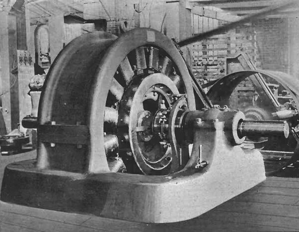
| A Typical Alternating Current Induction Motor of 125 Horse-Power. |
From recent careful tests, made by disinterested experts, it appears that the cost per horse-power per annum in large and economical steam plants (1000 horse-power or more) in Buffalo, coal costing $1.50 per long ton, is about $33 for power used 11 hours per for 365 days a year, or $51 per horse-power for 24-hour power, for 365 days. This cost includes interest on cost of plant, insurance, taxes, operating expenses and depreciation and repairs. As the coal cost is low as compared with other cities, and as the load of the particular plant tested is unusually steady and uniform, it is probable that this cost of steam power is as low as will be found within the area of influence of Niagara electric power. It remains, therefore, to determine the approximate cost of this power, delivered at certain typical points within this area.
| |||
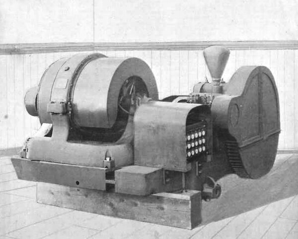
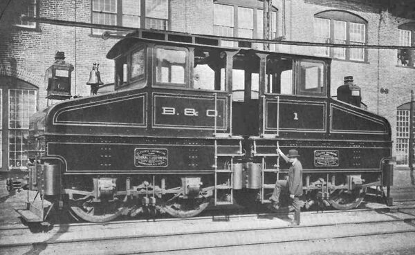
| Ninety-Five-Ton Electric Locomotive Built for the Baltimore and Ohio R.R., at Baltimore, Md., U.S.A., by the General Electric Co., New York. |
| |||
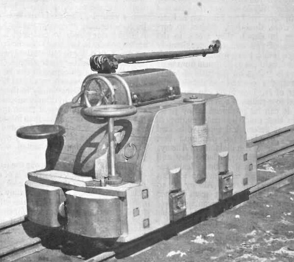
| An Electric Mine Locomotive. |
About a year ago, there appeared in one of the technical journals, a very interesting and able paper by Messrs. Houston & Kennelly, two well-known American electrical engineers, entitled "An Estimate of the distance to which Niagara water power can be economically transmitted by electricity." Assuming certain initial data, the paper estimated, in detail, the cost of delivery of certain maximum amounts of power to three points, Buffalo, Syracuse, and Albany, at assumed distances by wire, from Niagara Falls, of 15, 164, and 330 miles, respectively. These costs were then compared with the cost of steam power, generated locally in large quantity, under most economical conditions, and certain conclusions were drawn from the comparison. The paper, as was to be expected and de sired, created considerable comment and discussion among electrical engineers and in the technical press, and much of the data assumed and some of the conclusions drawn, were publicly criticised or questioned. The critics, however, apparently without exception, failed to appreciate the great difference in cost per horse-power and average efficiency between electric generators, motors and transformers of the si/e usually employed in central station practice, and those of 1000 horse-power capacity or more which will necessarily be used in the Niagara work. They also failed to recognize the fact that, inasmuch as Niagara power will be transmitted and sold in bulk in very large quantities, it is reasonable to assume that the " load factor"
(ratio = Average load / Maximum load)
will be considerably higher than is usual in central station electric lighting practice. The cost of local steam power assumed in the paper was also criticised as being too low, but as the figures were taken from tables carefully prepared and published by a well-known engineer, and as they agreed closely with those obtained from the test already referred to, they were probably accurate. While some of the data and assumptions used by Houston & Kennelly were, doubtless, subject to correction in detail, they were, in the opinion of the writer, approximately correct, if taken as a whole.
The conclusion to be drawn from their figures is that on the basis of prices and voltages assumed and detailed, the power of Niagara Falls can be trans mitted to a radius of 200 miles, cheaper than it can be produced at any point within that range by steam engines of the most economical type, with coal at 12s., or about $3, per ton; that Niagara power can maintain at Albany, in New York State, a large day and night output cheaper than steam engines at Albany can develop it; but that for power taken at Albany for 10 hours per diem, the best steam engines have somewhat the advantage over Niagara, unless exceptionally favorable conditions of load could be secured for Niagara power.
Speaking of electric transmission from water powers in general, Houston & Kennelly say: The broad conclusion to which an inquiry of this nature inevitably leads, is that while under ordinary conditions the commercial limit of electrical transmission of power from water powers of less than 500 kilowatts can hardly exceed fifty miles, the radius at which it will be profitable, with good fortune and management, to electrically transmit a water power aggregating 50,000 kilo watts, or more, is, perhaps, today, two hundred miles, and that it might be commercially advantageous for such a large water power to undersell large steam powers at twice this distance with no profit, in order to reduce the general expense upon delivery nearer home. The reason for this difference in the transmission radius between small and large water powers, lies obviously in the fact that electrical and hydraulic machines can be built and purchased much more economically in large sizes than in small, so that the cost of producing and of maintaining one kilowatt is very much less for large than for small water powers."
While time alone can prove the truth of these conclusions, the writer is of the opinion that, with the present cost and efficiency of steam generators, they are substantially correct. If, on the other hand, a method be discovered for transforming the heat energy of coal into electricity direct, at an efficiency com parable with that of modern electrical apparatus, the area of influence of Niagara electric power will, undoubtedly, be contracted. While such a discovery would undoubtedly be a great one, it should be stated that there is no prospect, at present, of its accomplishment. In any event, it is probable that the Niagara power company will find enough profitable business to insure a satisfactory return on the money which they have invested.
