[Trade Journal]
Publication: The Journal of Electricity
San Francisco, CA, United States
vol. 7, no. 5, p. 69-77, col. 1-2
The Kootenay-Rossland Power Transmission.
BY GEO. P. LOW.
PART I.
KOOTENAY district includes Columbia lying on the Canadian north of Spokane, Wash. It is country. The crest of the Rocky its eastern boundary and the Selkirk and Purcell ranges, paralleling the Rockies, run through its center and thus separate it into its east and west divisions, each of which has an average width of from sixty to seventy-five miles, by a length of over two hundred miles. The district is very heavily wooded with dense underbrush or of bleak and barren granitic formation, according to altitude or precipitousness, and the wild, rugged grandeur of mountain scenery, which has, above all other features, made the Canadian Pacific Railway world-famed, is mostly located with-n confines. Curious indeed too, are the formation of its lakes and water courses. Inland fresh water seas, almost innumerable, and of all shapes and sizes, mark the country on every hand, and the multitude of rivers supplied from them eloquently bespeak permanence for the sources of mighty Columbia. Water is everywhere, as are also the Indian and frontier names, euphonious or otherwise, such as the town of Illecillewaet, the Spillimadieen River, or Horse Thief Creek. But an idea of the broken and erratic topography of the Kootenay district can not be better conveyed than by reference to the seeming antipathy which the Columbia and Kootenay rivers bear each other in their early courses. The Columbia has its source in Upper Columbia Lake, whose head or southern extremity is about fifteen miles above the Canadian boundary line. Thence the Columbia flows in an almost due northwesterly direction for practically two hundred miles, whence it turns southerly and then westerly, first through the West Kootenay district and then into the United States and on to the Pacific Ocean.
| |||
| Figure 1. - Lower Bonnington Falls and Power House. |
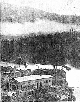
A few miles east of the Columbia, at a point some sixty miles below its source, are two comparatively small lakes a mile or so apart. From the northerly one the Beaver Foot River rises, eventually reaching the Columbia; in the southerly lake the Kootenay River finds its source and continues down in a south?easterly direction, parallel with and at a distance varying from ten to fifteen miles from the Columbia River, though the streams flow in opposite directions for about sixty miles. When the head of the Columbia is reached and further paralleling is impossible, the Kootenay approaches within three miles of its rival river but quickly turns from it, flowing away one hundred and fifty miles further south into Montana, whence it retraces its course into British soil and finally joins the Columbia near Robson, some thirty miles north of the boundary line, Before doing so, however, it forms the Kootenay Lake, which is perhaps sixty miles long and from four to eight miles wide, and from the lake it continues to the Columbia through a broad, resistless water course something less than fifty miles in length. It is near the lower end of this portion of the Kootenay River, which forms the connecting link between Kootenay Lake and the Columbia River, that the Bonnington Falls are located, and at the lower Bonnington Falls is the generating station of the West Kootenay Power and Light Company, Limited. Thirty-two miles distant is Rossland, which is one of the newest and most prosperous and promising gold mining camps in British Columbia, and in which electricity is not only fast superceding all other forms of power in mining work, but is also even put to characters of mining service ordinarily classed as impossible of accomplishment. It has been my fortune to make personal examinations of the principal electric power transmissions of the West, and it is without hesitation that I state that in none of them is the West Kootenay transmission exceeded in points of thoroughness, of engineering design and commercial advantage. While the heroic manner in which it has grappled with every phase of the power problem as applied to mines, and the thoroughness with which it has worked out the complete solutions of these problems, enables it to stand alone as one of the most perfect mining transmissions to be found on the Pacific Coast. After long familiarity with experiences which have been had in California transmissions in attempts, generally futile, to operate mining hoists by induction motors, one is quite unprepared on reaching Rossland, to be informed that for months the War Eagle hoist at that place has been operated by a 300 horse-power induction motor and that the service therefrom has been absolutely perfect, so perfect indeed, that the Le Roi mine is to have its steam hoist displaced by a hoist operated by a 500 horse-power induction motor after the plan of the War Eagle hoist as soon as the Kootenay company has enlarged its plant and can furnish power for its operation. All electrical and mechanical details concerning these and many other features of all-important interest will be given in this article.
| |||
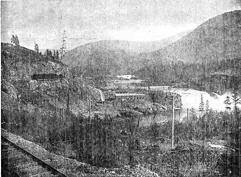
| Figure 2. - A General View of Bonnington Falls and the Power House. |
Among these further features may be briefly enumerated the extraordinary thoroughness and reliability of the water power development, the difficulties which attended the building of the pole line over a rugged route wherein could he found but a few miles of practically level line out of the entire distance, and where, in its length of 32 miles the altitude of the line varies at different points by over 2200 feet. A novelty in the line construction consists in the use of roofed poles and cross-arms, and, the Columbia River is crossed with a single span 1500 feet in length without the use of supporting cable. The plant was built essentially for power purposes and of its present load only about twelve per cent. is in lighting, the remainder being in both synchronous and induction motors in mining duty for the operation of compressors, hoists, rock breakers, roasters, bricquetting machines, blowers, machine shops, and other equipments used in and about mining and smelting work.
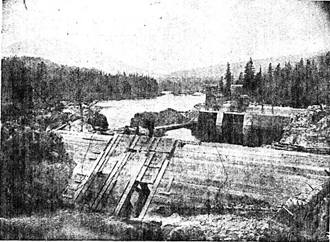
The general view of the Bonnington Falls, upper and lower, and the country about the power house is given in the accompanying engraving. Here the Selkirk Mountains rise to an elevation of over 1300 feet above the river, or to an elevation of about 3500 feet above the sea level, and the beautifully snow-capped peaks of the rugged range, together with the grandeur of the chain of the falls, forms a charming and picturesque scene. At low water the falls, both upper and lower, are capable of delivering 267,000 horse-power, but the West Kootenay company has thus far attempted to utilize only a portion of the lower falls, which, under the 40 foot head available at extreme low water, are capable of delivering 100,000 horsepower. The river is 400 feet wide at the lower falls and in developing a portion of its water power, the West Kootenay company constructed a canal 650 feet in length and some 26 feet in width, all through the hard country rock. Towards its lower end the canal widens out into a forebay 54 feet in width, the forebay being closed in by a solid concrete dam 32 feet high and 26 feet in width at the bottom, tapering to six feet in width at the top. Between two high bluffs at a point in the head race, 150 feet above the concrete darn, has been constructed a wooden darn sloping at an angle of 42 degrees up stream and having a vertical height of 44 feet. The sills and timbers of this darn are spaced five feet apart, and all timber, including sills, are of 12 X 12 material solidly bolted to the rock, the whole being then planked by a double layer of four-inch planking. In the bottom of this dam are five sluice ways and its object is to break the impact of water flowing into the head race from the canal during high water, or, in general, to insure the control of the water entering the forebay at all times.
| |||
| Figure 3. - Wooden and Concrete Dams and Forebay. |
| |||
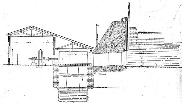
| Figure 4. - Rear View of Power House Showing Draught-Tube and Tail Race. |
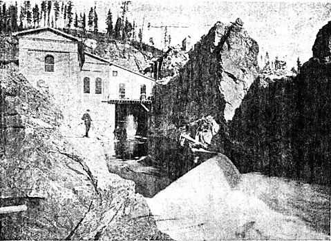
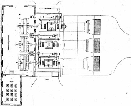
Lower Bonnington Falls have an extreme difference of level of 32 feet, which measures the head of water available at the power house. The main concrete dam is provided with three feeders, two of nine feet each and one of ten feet. The upper ends of the feeders sire closed by gates which measure respectively 12 feet by 13, 12 feet by 13, and 13 feet by 14. These gates are of wood, and consist of a framing of 12X 12 timber to which is solidly bolted eight-inch planking. The two outside frames extend upward of 38 feet and to the walls of each pit are bolted the racks for raising and lowering the gates. The gates are further provided each with a small iron floodgate, 12 inches by 12 inches in size, and the main gates are raised and lowered by means of headgate irons rigidly bolted to the top of the dam. The winch controlling thy headgate irons are operated by one man. These and other features are admirably sin mil ill the drawing on page 73 showing the end elevation of the dam, power house and tail race. The three steel penstocks, each nine feet in diameter by 20 feet in length, run through the concrete darn into the hydraulic section of the power house near the base of the dam, and from each penstock is carried a ten-inch stand pipe, the height of which nearly reaches the top of the dam. The back of the dam practically forms one side of the power house and tail race, the latter extending at right angles to it and consisting of a pit approximately 30 feet in depth by 20 feet in width, extending nearly the length of the power house, which is 66 feet. In the clear water the tail race is flanked by built masonry and concrete retaining walls which vary from four to six feet in thickness and extend upward to approximately the level of the power house floor. The floor plan of the power house shows the arrangement of the turbines and their mode of connection to the generators. Bolted to the lower end of each penstock is a 13-foot casting containing one pair of 39-inch horizontal cylinder gate turbines. To these castings or wheel housings are bolted the draft tubes, which are 22 feet in length and ten feet in diameter at the lower end. The housing is supported on each end by the retaining walls of the tail race and are further carried by I beams. The turbines for driving the exciters are supplied with water taken from the main turbine housings in the manner shown on the ground plan of the power house.
To be more explicit, the three 40-kilowatt, 125-volt multipolar exciters are direct-driven from independent, horizontal, 12-inch registered gate turbines which are contained in the cast iron flumes, the latter in turn supported by transverse beams bolted to the Main beams of the large wheels, while bolted to the cast iron flumes are the draft tubes and feeders. The latter are connected to the shaftings of the large wheels from which they derive their water supply. The portion of the power house containing the generators and switchboards together with the transformer house built thereon as an L, is bedded on the solid granite rock, which, after being suitably dressed and surfaced with concrete, gave most perfect foundations for the heavy machinery to be placed therein. A single roof covers the entire structure with the exception of the transformer house which is independently roofed. The building is fireproof, with walls of brick and roof of wood covered with galvanized iron. The inside dimensions of the turbine house are 25 feet by 64 feet; those of the generator room are 31-1/2 feet by 66 feet, while the transformer house measures 17 feet by 28 feet. A flight of nine stairs takes one from the floor of the generator room to that of the transformer house, the difference in elevation of the two floors furnishing space for the blowers of the air blast transformers and ducts, as will be described hereafter. The height of the building from floor to the ridge of the roof is 40 feet, and ample room is thus provided for substantial framing on which to carry the high tension leads.
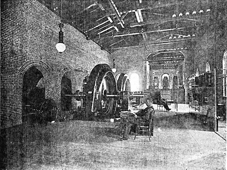
Two 750-kilowatt units have been in operation in this power house since last summer, and the third generator, which is a 1500-kilowatt unit, is at present under erection and will be in operation at the earliest possible moment in order to relieve the overload under which the plant is now laboring, as well as to take care of the increase in business awaiting its installation. Along with this generator, of course, is being erected an equivalent capacity in raising and lowering transformers which explains why these transformers do not appear in the photographs of the plant, although they are shown as erected in the drawings. The comparatively small difference in the relative sizes of 1500 and 750-kilowatt units, even when run under the same speed as is done in the present case, is strikingly shown in the general plan of the power house, from which it is also obvious that two 1500-kilowatt units with accompanying wheels may be substituted for the two 750-kilowatt equipments as installed at any time, if desired, without necessitating changes in the power house.
| |||
| Figure 5. - Interior of the West Kootenay Power House. |
These generators are of the standard General Electric revolving field type as built by the Canadian General Electric Company, as is also the entire electrical equipment of the whole installation with the exception of the induction motor operating the War Eagle hoist at Rossland, which was built at the Schenectady works of the General Electric Company. The generators run at 180 revolutions per minute, have forty poles, and deliver 60? cycle, three-phase current at 1100 volts delta. Underground water proof ducts carry the generator leads to the switchboard, which, when completed, will consist of three exciter panels, three generator panels, and three transformer panels. Nothing of novelty is imparted in the switchboard, as all instruments, appliances and methods are of standard General Electric varieties, with the single exception that the generators are thrown into synchronism on the "out" of the synchronizing lamps, whereas it is the usual practice to synchronize with lamps at full candle power. In this connection it is interesting to note that at the outset considerable difficulty was experienced in synchronizing the generators, but the trouble was finally located as being due to the fact that the slip-rings on the revolving fields were out of true one-eighth of an inch. Rotation thus introduced a varying resistance in the contact between the brushes and slip-rings which, though imperceptible in the voltmeter and ammeter readings, made synchronizing an uncertain performance. However doubtful station engineers may he that the trouble experienced was due to the cause ascribed, it is certain that after the slip-rings were turned down no further difficulty was encountered in synchronizing, which is now done with perfect ease under a variation of zoo amperes.
Ducts placed under the floor carry the leads from the transformer panels to the raising transformers. There are twelve of these, each having a capacity of 250 kilowatts and wound for 1100 volts on the primary with either 11,620 volts 20,100 volts on the secondary, according to whether delta or Y. The higher potential of 20,100 volts is delivered to the line.
It is the opinion of the writer that if it had been the general custom to install air-blast transformers in the manner adopted by the West Kootenay Power and Light Company and to have maintained them under the same care and attendance as the Kootenay company is administering to the air-blast transformers in its installation, a greater degree of success would have attended their use than has been the experience of a few of the many transmissions which have adopted them. More detailed reference to this matter will, however, be given in describing the step-down transformer installation at the Rossland sub-station, as the ideas to he conveyed may be then more clearly set forth by reference to the structural drawings presented, and the principles involved apply equally well to the transformer house at the generating station.
| |||
| Figure 6. - End View of Power House, Tail Race and Dam. |
In this transformer house three 60-inch Buffalo blowers together with the two horse-power, t to-volt induction motors from which each is driven, are placed under the platform forming the floor of the transformer house, in the space indicated by the slotted grating behind the stairs. These blowers furnish an air blast to the transformers through large ducts or tunnels after the manner and for the purpose to be described later. The high tension circuits are led from the transformer to porcelain insulators placed on framings overhead in the transformer house and generator room whence they are carried to the line out through eight-inch, vitrified, terra cotta piping built in the front wall of the station. Fifteen such pipes exist, thus providing for five three-phase circuits, and the outside orifices of these outlets are roofed.
| |||
| Figure 7. - Floor Plan of Power House. |
THE POLE LINE.
The profile of the Kootenay-Rossland transmission astonishes one because of the extreme irregularity of the country it traverses from one end to the other. In fact it resembles the work of the tracing pen on the recording voltmeter chart of a badly regulated incandescent plant, or perhaps even of a railway power service, much more than the profile of a transmission pole line. There is altogether not over a level mile or two in its whole length, and the grades are of all degrees of steepness, reaching the maximum at about 70 per cent. Its length is practically 31 miles, in traversing which its altitude above sea level varies by over 2200 feet.
| |||
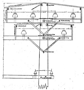
| Figure 8. - Detail of Pole and Cross-Arm. |
| |||
| Figure 9. - A Side View of Pole and Cross-Arm. |
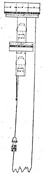
Aside from the features enumerated, the pole line embodies two characteristics, each of which is, so far as the writer is aware, without precedent in transmission practice. The pole line is double, and on one of these lines both cross-arms are roofed or snow-shedded. The other distinguishing feature consists in the span of 1500 feet that the line wires take in crossing the Columbia River, these wires being unsupported by cable as will be described. Both pole lines are of a very substantial type of construction, being round, specially selected cedar, and varying in length from 30 to 65 feet, according to location. They are set 100 feet apart, or 50 to the mile, with all corners and curves properly guyed. The right of way lies through a heavily wooded country throughout which a 100-foot clearance has been made from each pole line. The first line built was constructed in the ordinary manner; that is, without roofing, but before it was placed in service the wet snow piled up on the cross-arms to a height of nearly two feet in places, which led to the determination to roof in the second line to prevent any trouble that it was believed would arise from snow. It should be explained that in the Kootenay country there is no Wind whatever during snowstorms and hardly any wind arises at any time during winter. As the snow is of a very wet nature there is nothing to prevent it piling up to the depth named on cross-arms, or its clinging to the transmission lines until the diameter has been increased to four or even six inches, and oftentimes the accumulation will remain until dissipated by the Chinook winds so characteristic of northwestern regions.
 |
| Figure 10. - Details of Pin. |
The accompanying cuts give the dimensional data of the details and materials used in snow-shedding the second high tension line. As will be seen therefrom both cross-arms are roofed, the upper one, which carries four insulators, being covered with a cedar roofing 24 inches wide, while the width of the roof over the lower arm is but one foot four inches. The details of the construction are, however, given so fully in the drawing on the next page that a description of them would be redundant.
As a matter of engineering information it may be stated that the following comprises the list of materials for each pole:
It will be seen by reference to Figure 10, that the pills used are of specially heavy construction, having a shank 2-7/8 inches in diameter and 5 inches long from the shoulder. The length of the pin over all is 11-1/2 inches, which gives 6 inches from the top of the cross-arm to the top of the pin. These pins are of locust and the treatment administered to them consisted in boiling them in paraffine oil, after which they were taken out, and when cooled they were dipped in hot paraffine oil. No further treatment was given. Porcelain insulators of the Redlands type are used throughout, and while the three wires of a circuit in three-phase transmissions are generally placed so as to form an equilateral triangle, the wires of the Kootenay transmission form an inverted isosceles triangle with 20 inches on the base and 22 inches on each of the sides.
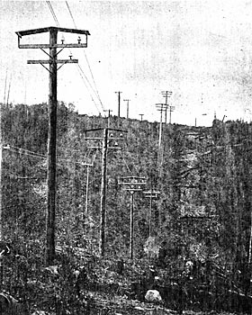
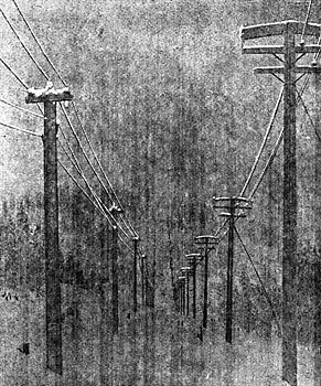
The illustration on page 77 was taken from the door of the sub-station in Rossland last winter during a period when the snow had accumulated to a depth of from 10 to 12 inches on the cross-arms of both the roofed and unroofed pole lines. It remained in this condition for considerably over a week and service was continued as usual over both pole lines without interruption from snow or any other cause during this period. If any leakage existed between the wires on the unroofed pole line, or to ground, it was impossible to detect it with the appliances at hand and the standard station instruments were in no wise affected by it to any appreciable degree. It is probable therefore, that after the experience of last winter, such other pole lines as the West Kootenay company may erect will not be roofed.
| |||
| Figure 11. - Tower and Gallows Frame on Rossland Side of Columbia River Crossing. |
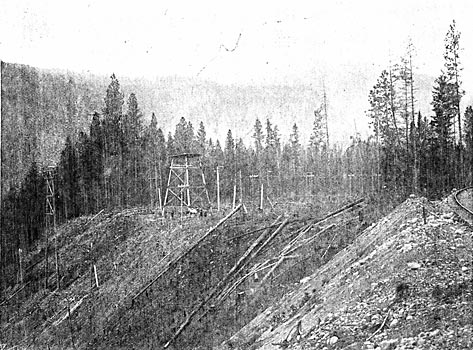
At present two circuits are completed and have been in successful operation for several months, and the third line is now under construction. These lines are of No. 0, B. & S. gauge medium hard drawn copper wire, with the exception of where they cross the Columbia and Kootenay Rivers, where they are changed to No. 000 bimetallic wire, the increase in cross-section being for the purpose of maintaining the conductivity of the bimetallic wire equal to that had in the regular line. The Kootenay River is crossed in a single span of 600 feet, while the span across the Columbia River is 1500 feet in length. These spans are unusual because of their length and the fact that, as previously stated, they are not supported by strain cables. The methods pursued in crossing each river are the same and on page 76 is given a view of the tower and strain frame on the Rossland side of the Columbia River at the crossing. The No. 0 copper lines terminate at the square strain frame shown near the center of the photograph; and at this point also, the bimetallic lines are anchored and carried thence to the 125-foot tower in front, whence begins the span across the river. There is a sag of 52 feet in the total stretch of 1500 feet, and the strain is supported on ordinary porcelain insulators placed close together and mounted on very substantial framings. At times wet snow has adhered to the line wires at these crossings until it has reached a diameter of about four inches, yet trouble has not arisen therefrom nor from swinging crosses at the rivers, as the separation of six feet that has been placed between wires at these points has proven adequate to prevent it. In fact the service has not been interrupted since the starting of the plant, but on two occasions, one line or the other was broken by the falling of trees that were supposed to be beyond reach tot the lines. The photograph showing the tower and strain frames at the Columbia crossing was taken during construction, hence the line wires at the crossing are not shown.
| |||
| Figure 12. - the Method of Transposition. |
At a point three miles from the sub-station in Rossland branches are taken off at right angles and carried to the town of Trail, B. C., which is four miles by pole line from the main line. At Trail, where is located the great smelter of the Canadian Pacific Railroad, the three-phase current is taken into a neat brick sub-station containing the usual equipment; of choke coils, lightning arresters, and the high and low tension switchboard panels necessary for the safety and control of the three 135-kilowatt, oil-insulated, air-cooled, static transformers therein. These deliver three-phase current at 550 volts for the operation of various portions of the smelter.
| |||
| Figure 13. - Ten Inches of Snow and 20,100 Volts. |
So variegated are the uses to which electric power is put in these premises, and so characteristic is the installation as representing the various kinds of service that may be rendered with the utmost reliability by electric power, that specific reference to the duties performed by some of the motors will be of interest. Two 75-kilowatt synchronous motors, for instance, drive Connorsville blowers for the blast furnace, each motor operating a separate blower, while a third Connorsville blower is driven by a 50 horse-power induction motor. All the remaining motors about the smelter are of the induction type. A 50 horse-power motor drives a rock breaker and another 50 horse-power motor operates the lead mill. The machine shop is driven from a 30 horse-power induction motor; another one drives the O'Heara roasters in the O'Heara building, and a third 30 horse-power motor drives the Bruttner roasters in the Bruttner building. These motors are all of Canadian General Electric manufacture and the only Westinghouse motor about the smelter is a 40 horse-power, type C induction motor which operates a bricquetting machine. The limit of transformer capacity has been reached in the service thus far installed in the Trail smelter, and such eminent satisfaction has resulted from the use of electric power that numerous extensions, among which is to be an electric tramway, are to be installed at once. During the-year the Trail line will probably be taken from the main line and carried through to the Rossland sub-station.
(To be concluded in June number.)
