[Trade Journal]
Publication: The Journal of Electricity, Power and Gas
San Francisco, CA, United States
vol. 7, no. 6, p. 85-92, col. 1-2
The Kootenay-Rossland Power Transmission.
BY GEO. P. LOW.
THE ROSSLAND SUB-STATION.
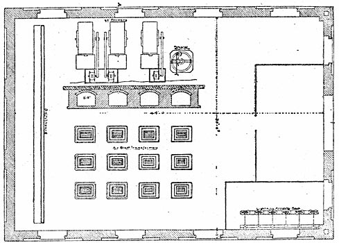
THE transmission lines enter the sub-station at Ross-land through portholes lined with eight-inch terra cotta piping similar to those provided at the power house. As one enters the door of the sub-station the standard General Electric lightning arresters used are placed on a marble board in a corner at the left as shown in the floor plan appearing on page 86. The choke coils used are an innovation in that each consists of a core twelve inches or so in length turned in the center of a stick of kiln dried and well filled timber about five inches square, by from six to eight feet long. About this core insulated wire is wound until the space is filled so that the choke coil thus formed resembles an exaggerated form of spark coil with its terminals carried out to the respective ends of the timber on which it is wound, these timber ends being strapped to the top of high tension insulators through which the choke coil is cut into the line. Such choke coils are placed in every line, not only at the sub-station but at every power service. At preset the Rossland sub-station contains but six 250-kilowatt step-down transformers, although six others, each of equal capacity, are being installed with the new 1500-kilowatt generator. The line wires are carried to the high tension switchboard at the rear of the station on high tension insulators supported by framings that hang from the roof girders, and the usual facilities are provided to afford safety and celerity in the handling of both the high and low tension sides of the transformers. These latter are of the same type and size as those installed at the power house, with the exception that the primaries take either 9600 or 16,600 volts, according to whether connected in delta or Y, while the secondaries deliver 2200 volts in three-phase current, which is the potential used on all the lighting and power distributing circuits in and about Rossland.
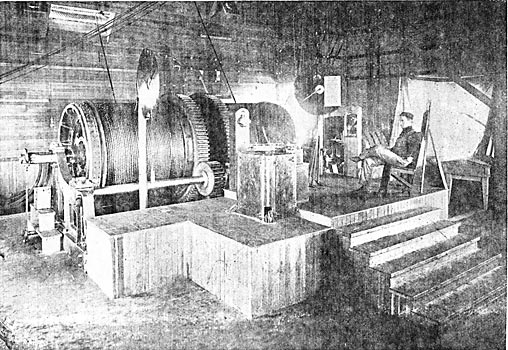
| |||
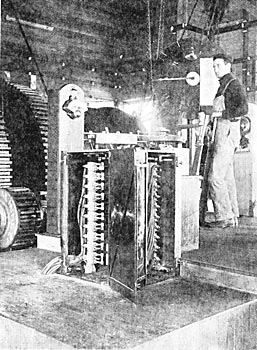
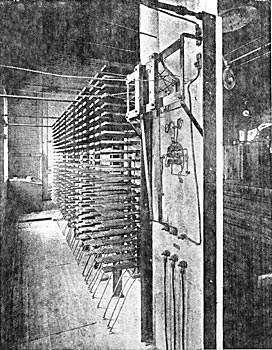
| Figure 22. - View of Controller for Induction Motor at War Eagle Mine. |
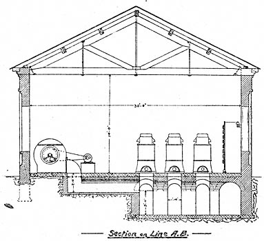
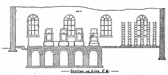
Here may be explained, through the accompanying cuts presenting the floor plan, end and side elevations of the substation at Rossland, the very meritorious method which the electrical engineer of the West Kootenay company has devised for applying the air blast to the transformers at the power house and at the Rossland sub? station. As in the power house, the blast is supplied by three sixty-inch blowers each driven by belting from a two horse-power 100-volt induction motor. Instead of carrying this air blast to the transformers through small air ducts as is usually done, the engineer of the Kootenay plant has provided subways large enough for a man to enter and move about in. The manner in which the blowers supply air to these subways is shown in the end elevation of the sub-station, while the subways themselves, as is shown in the side elevation, extend in line with and directly under each row of step-down transformers. The idea of this arrangement will be understood when it is stated that each week the transformers are cut out of service one by one and the air ducts in them are each and every one examined and cleaned by a man who enters the subway in order that he may have access to the lower end of the air ducts in the transformer. His work in cleaning the transformers is facilitated by the use of compressed air, which is obtained in both the power house and the sub-station from a single drill compressor driven by an induction motor. It is safe to say that so long as this method of transformer examination and cleaning is faithfully carried out the Kootenav transmission will never lose a transformer from the choking of its air ducts. Slides for regulating the amount of air to be delivered to each transformer are provided and of course the subway is always air tight and the man who cleans the transformers is under the increased atmospheric pressure of the air blast while at his work.
| |||
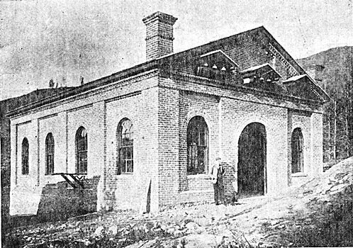
| Figure 14. - the Sub-Station at Rossland. |
| |||
| Figure 15. - Interior of Sub-Station at Rossland. |
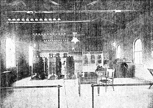
The photograph showing the interior of the sub-station was taken shortly after the plant started operations an since then important additions have been made. The distributing switchboard at the right in the rear has had new panels added to it to accommodate other circuits. The third blower has been added and immediately in front of it, as shown in the floor plan of the sub-station in Figure 16, has been placed the induction regulator by means of which the potential of the outgoing lighting service is controlled by the sub-station attendant independent of the power house.
| |||
| Figure 16. - Floor Plan of Sub-Station at Rossland. |
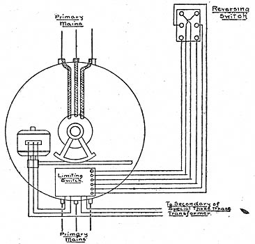
This is a new device of the General Electric Company bearing the designation "type I. R. T. class 4-20-60 form A." It is wound for seventy amperes per phase at 2200 volts and has a range of 220 volts in either direction. It is described as consisting of an induction motor with vertical shaft, which is connected through bevel and worm gearing to the shaft of a pilot motor placed on top of the case so that the rotor of the induction regulator may be made to turn a given arc in either direction and in so turning raises or lowers the electromotive-force in the primary mains passing through the stator windings as desired. The pilot motor is manipulated from a simple double-pole, double-throw reversing switch placed on the switchboard; and this motor too is an induction motor. All details of this novel regulator together with those of the limiting switch placed thereon are given in Figure 20. At present this regulator is used only on the lighting circuits, nor is its use contemplated on the power service.
| |||
| Figure 17. - End Elevation of Sub-Station at Rossland. |
| |||
| Figure 18. - Side Elevation of Sub-Station at Rossland. |
All the electric lighting in Rossland, in both arc and incandescent services, is rendered from alternating circuits, and indeed the only use to which direct currents are put in the Kootenay plant is for the excitation of generators and synchronous motors. The electric lighting, load reaches a maximum of nearly 400 horse-power. Enclosed. alternating arc lamps are used exclusively and these are burned from the 110-volt commercial circuits. The ultimate distribution is on the Edison three-wire system through the use of type H transformers taking either 1400 or 2080 volts on the primary and delivering 230 volts across the outsides of three-wire service. The utmost care has been exercised in preserving the balance on the three-wire distribution circuits as well as in balancing the primaries of the commercial transformers on the three-wire, three-phase, 2200-volt circuits, and this balancing has been carried out so well that it has never been observed that the phases of the 2200-volt circuits have been more than to amperes out of balance.
| |||
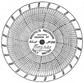
| Figure 19. - Typical Chart of Voltage Regulation. |
As stated heretofore, the principal interest in the Kootenay-Rossland transmission centers in its application of electric power for mining and milling purposes, the most notable installations being in the properties of the War Eagle Mining and Development Company, the British Columbia Bullion Extraction Company, the British American Corporation, and the Gertrude, Big Three and Iron Mask mines. These six properties alone consume about seventeen hundred horse-power in the operation of hoists, compressors, crushers, conveyers, ventilating blowers and in electrolytic work. The bulk of this power is delivered by induction motors, for as a general rule, synchronous motors have been applied only to the driving of compressors.
The initial illustration gives a general view of the controller of the War Eagle hoist which will he seen to be a standard General Electric induction motor. It is a three-phase equipment operated at 2300 volts, has twenty-four poles and delivers three hundred horse-power at three hundred revolutions per minute. Its technical designation is, therefore, "I 24-300-300 form A." The rotor shaft is geared to a Ledgerwood type double drum hoist through double reduction gearing, having a ratio of reduction of 300 to 40. The War Eagle shaft is at present down a little beyond the 600-foot level and the maximum load raised amounts to eight tons including the load, cage and rope, the speed being 720 feet per minute for this load.
| |||
| Figure 20. - Connections of Induction Regulator. |
| |||
| Figure 21. - Connections of Limiting Swithc. |
Interest of course centers in the method of speed control, each technical detail of which is fully shown in the accompanying photographs and drawings. Secondary control is used exclusively; that is, no effort whatever is made to control the primary current, while the secondary current, or that induced in the rotor circuit, is varied by the introduction of external resistance. The controller proper, shown in Figure 22 is a duplex one inasmuch as the movement of the controller handle manipulates both the primary and secondary circuits of the motor, the former for making, breaking and reversing and the latter for the control of the variable external resistance. The controller on the high tension or stator side operates in a bath of mineral oil. The secondary windings are led to three collector rings placed on the shaft with the rotor, and upon these rings bear carbon brushes which cover about 90 degrees of the surface of the rings, this being a necessary procedure because of the heavy amperage to be taken off. The maximum 'secondary electromotive force obtained is in the neighborhood of seventy volts. From the rotor brushes the current is carried to the low tension side of the controller through which resistance may be cut in or out of the rotor windings in ten steps. The resistance consists of cast iron grids arranged upon a large slate resistance board as shown in Figures 25 and 26. With the maximum load of eight tons gross at a speed of 720 feet per minute the current reaches a maxim um of 110 amperes per phase, dropping back to 90 amperes as the load decreases by the reason of the cage nearing the surface. With a load of men the maximum current is 70 amperes per phase.
The principle under which variable speed is attained in the operation of this induction motor is found in the fact that while in the synchronous motor, exact synchronism between the motor and generator must always be maintained, yet the induction-motor is so constituted as to be nearly independent of any magnetic slippage that may exist between its stator and rotor. When under full speed the motor is practically in synchronism with the generator, but with the generator speed constant a variable speed in the motor is best attained by the introduction of methods that will provide variable slippage as desired, for the greater the slippage the slower will be the speed of the rotor. The equipment at the War Eagle hoist is so controlled that the speed of the motor may be varied from forty revolutions or less per minute to its full speed of three hundred revolutions.
As will be seen in Figure 22, the high and low tension controllers are geared together, this being done in such a manner that both are actuated at proper intervals by the manipulation of a single controller handle. The only function of the electrical equipment is that of hoisting, for as the cages are balanced one against the other it is the rule that power is applied for either direction of rotation. Braking is done through the application of band brakes by means of the hand levers shown in the illustration on the next page.
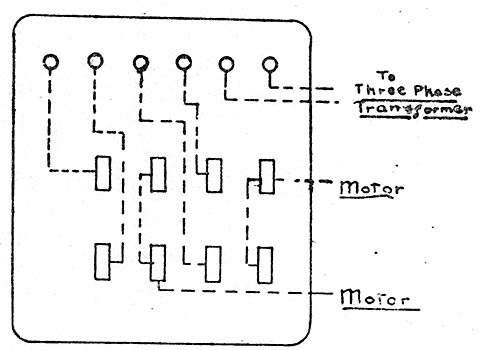
The subjoined diagram of circuit connections shows the development of the reversing cylinder as applied to the high tension controller. The head board of this controller has six terminal lugs, those numbered 1, 2 and 3 being for the service leads, while those numbered 4, 5 and 6 are carried to the motor. The controller applies the full line potential of 2300 volts to the stator, and it serves not only as a make and break switch but also as a pole changer for reversing. The short circuiting of terminals 1 to 4, 2 to 6, and 5 to 3, causes a given direction of rotation, while the short circuiting of terminals 1 to 4, 2 to 5, and 3 to 6 causes an opposite direction of rotation, all as shown in the attached circuit diagram. Mineral seal or any high grade transformer oil may be used for the bath for this high tension controller, which gives perfect satisfaction in operation.
| |||
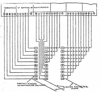
| Figure 23. - Connections of Induction Hoist Motor and Controller. |
| |||
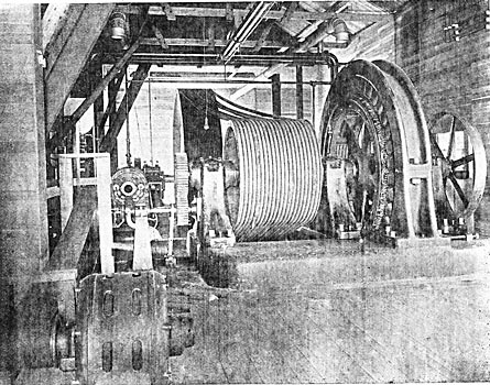
| Figure 24. - General View of Induction Hoists at War Eagle Mine. |
| |||
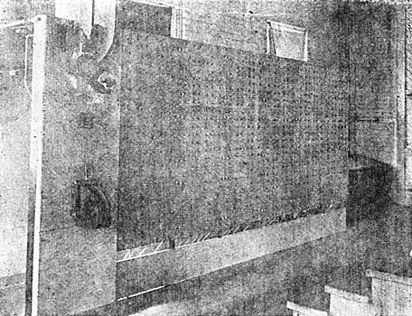
| Figure 25. - Front View of External Resistance Board. |
The connections of the circuits by means of which external resistance is cut in and out of circuit with the rotor windings through the low tension controller are outlined in Figure 23, and in Figure 27 is given the assembly diagram of the stationary cast iron resistance as mounted on the slate resistance board shown in front and back views in Figures 25 and 26. It must be understood that the terminals at the bottom of the slate panels appearing in the upper portion of Figure 23 are the same as thus shown at the bottom of Figure 27. The resistance strip: shown so clearly in Figure 26 consist of cast iron grids each in three waves, having a sectional area of about 1/2 by 5/8 inches and which have a running length of about sixty inches. These grids stand out from the board about 14 inches and they are in 23 vertical rows by 18 horizontal ones, and while the average cross section is as given, it varies slightly above and below that figure cording to the amperage carried.
| |||
| Figure 26. - Back View of External Resistance Board. |
| |||
| Figure 27. - Assembly Diagram of Stationary Cast Iron Resistance. |

Reverting to the scheme of low tension controller and resistance switch-board connections outlined in Figure 23, the leads from the slip rings on the shaft of the motor are carried to three sets of contact plates placed on the controller cylinder in ordinary arrangement, and upon these contact plates play the contact fingers which carry current successively to the resistance. Three posts are erected in the controller, each of which carries a set of ten contact fingers and two of the sets are shown in Figure 22. As stated, the maximum potential broken by the low tension controller is about seventy volts and the sparking is inconsequential.
One who is interested could spend hours in watching the operation of this hoist. It is easily handled by one man who finds himself with much less to do than has the motorman on an electric railway. In fact, the operation of the War Eagle hoist finds greater resemblance to street railway practice than one would imagine. The controller is manipulated with the same ease and celerity that attends the handling of a street railway controller, and it is more simple than the modern street railway controller in one regard, and that is the fact that reversal is accomplished in the War Eagle controller by the moving of the controller handle in a reverse direction rather than in the throwing of a special lever. At times when men are on the cage the hoist is "kicked" along by, the momentary application of power to the motor, which enables it to be run at much slower speed even than that possible with the controller on the first notch. At other times in hoisting ore, a dead load of five tons of which is almost always carried, the motor will be brought up to speed in a very few seconds and this without any abnormal inrush of current, for, as stated, during the writer's observations of the operation of the equipment under all conditions of service the motor intake did not exceed 100 amperes per phase. The motor has an efficiency of 92 per cent, and a full load power factor of 88 per cent., while at the slowest speed the power factor may drop to possibly between sixty and seventy per cent., but of this last statement no direct data is available at present. Current for the operation of the entire War Eagle equipment is sold by contract; i. e. on flat rates.
| |||
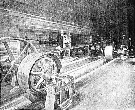
| Figure 28. - View of 400 H.P. Synchronous Motor, Driving 40-Drill Compressor at War Eagle Mine. |
The next feature of interest in the electrical installation at the War Eagle mine is found in the 300-kilowatt synchronous motor operating the 40-drill compressor illustrated in Figure 28. Three-phase current at 2300 volts is applied to this motor which runs at 200 revolutions per minute. It is of the revolving armature type, has thirty-six poles and, consequently, bears the designation "A P 36-300-200." A General Electric multipolar exciter, not shown in the illustration, is driven from a large pulley on the free end of the motor shaft, and this exciter has an output of nine kilowatts at 125 volts when operated at 1450 revolutions per minute. The compressor, which is of a double duplex type, is driven through independent ropes applied direct as shown in the illustration.
The method originally installed for starting the synchronous motor is also shown in the illustration given and it consisted of a thirty horse-power induction motor belted to a counter shaft through a friction clutch, this shaft carrying a spur gear by means of which the armature was brought up to speed. It can not be said that this equipment has been satisfactory, although it is in practical operation. The difficulties in its use rest first in the fact that in bringing the armature up to synchronism the compressor must, as well, be brought up to speed; and second, the 30 horse-power motor is too small for the duty required. It takes most exactly eight minutes to bring the motor up to synchronism, in doing which the 30 horse-power induction motor delivers from 120 to 130 horse-power, and, incidentally, has its temperature raised to a point somewhere above that conducive to a ripe old age. Although the small motor was still in service at the time of the writer's visit to the mine, it was shortly to be replaced by one having more than double its capacity. It should be stated in justice to the engineer of the Kootenay company that the starting device here discussed was not of his design or sanction. With the exception of the time consumed in starting, the equipment gives the best of satisfaction. A number of small motors ranging up to 20 horsepower in capacity are used in and about the War Eagle mine for ventilating purposes, driving conveyors, etc., and all these motors are of the induction type except that on the compressor.
At the Iron Mast Mine is a 75-kilowatt "S. K. C." synchronous motor, made by the Royal Electric Company of Montreal. It is a two-phase motor, with connections altered for three-phase service, and is started through an "S. K. C." induction motor and water rheostat, both of which appear in the illustration shown in Figure 29. The water rheostat consists of three fan-shaped blades plunged edgewise into a three-compartment tank of water, thus enabling the water resistance cut into each leg of the three-phase circuit to be varied according to the depth of immersion. The 75-kilowatt motor is belted to a jack-shaft in the manner shown, which drives two double-acting compressors having a combined capacity of ten drills. This is the only Stanley equipment on the Vest Kootenay circuit, and its service is most reliable.
| |||
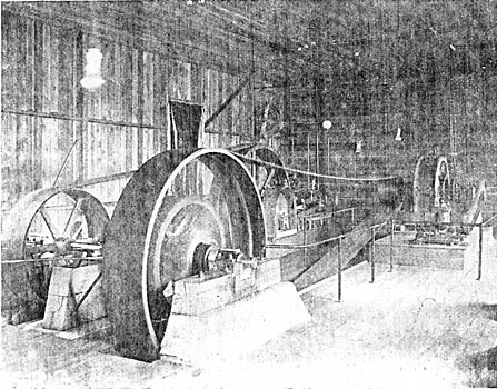
| Figure 29. - Stanley 100 Horse-Power Synchronous Motor, Driving 10-Drill Compressor at the Iron Mask Mine. |
In the Big Three mine is a 75-kilowatt General Electric synchronous motor, driving a seven-drill compressor in the manner shown .in Figure 30, while at the Gertrude mine is a 50 horse-power General Electric induction motor operating a hoist. The British Columbia Bullion Extraction Company has one 50 horsepower induction motor driving a rock breaker, and one 75-kilowatt synchronous motor operating all machinery about the mine, including generators for electrolytic work.
These motors, as well as all others referred to hereafter, are of Canadian General Electric manufacture. In the properties of the British-American Corporation are four 150 horse-power induction motors, each operating a double drum hoist through equipments which are in every way similar to those at the War Eagle mine. All underground work in and about Rossland is operated of 220 volts. Aside from mining work, the principle power installation is that of the general machine shop of Cunliffe & Abblett, where a 50 horse-power induction motor is installed.
| |||
| Figure 30. - 100 Horse-Power Synchronous Motor, Driving Seven-Drill Compressor at the Big Three Mine. |
There are many small motors ranging from one to five horse-power in size for the furnishing of light power in different industries in Rossland.
One of the most interesting points to be brought out by the Kootenay-Rossland transmission is the demonstration of the fact that the operation of synchronous and induction motors in large units for the driving of hoists and compressors will not necessarily create serious disturbance in the voltage of the distribution circuits, provided high voltage, ample fly-wheel effect and capacity prevails. During daylight the power and lighting circuits are operated in parallel, although they are separated and operated independently from the power house by night. The War Eagle hoist, however, is operated on an independent circuit by day, but at night it is cut into the power circuit at the Rossland sub-station. The result of this arrangement is shown in the reproduction of the recording voltmeter chart shown in Figure 19, which is that of the lighting circuit. From 6:45 p. m. to 5:00 a. m. the chart shows the regulation of the lighting circuit when on an independent line from the power house. At 5:00 a. m. the War Eagle hoist is taken from the power circuit and put on an independent line to the power house and the remaining power load is coupled in with the lighting load and carried on the second line to the power house. The voltmeter curve therefore, from 5:00 a. m. to 6:45 p. m. shows the regulation of the plant when all power with the exception of that for the War Eagle hoist is in parallel with the day lighting load. The chart given is that for an ordinary day, and, indeed, the charts run so evenly from day to day that each almost duplicates the other. The day in question there were in operation from 5:00 a. m. to 6:45 p. m. three 100 horse-power synchronous motors with an average load of 280 horse-power on compressor work; five 50 horse-power induction motors with an average load of 210 horse-power on the same, 3 of which were on hoists; three 30 horse-power induction motors with an average load of 76 horse-power, and one 40 horse-power induction motor carrying an average load of 32 horse-power. The lighting load consisted of 300 horse-power, which is high in proportion to the night lighting load because of the heavy 24-hour load carried. The report from the generating station for the same day shows that the variation reached 108 amperes at 110 volts, or an approximate variation of 205 horse-power, considering which the regulation is remarkably good. The secret of this is stated to lie in always maintaining a high voltage in relation to the motor ratings, with ample generator and water wheel capacity.
The conception and commencement of the work on the remarkably interesting transmission of the West Kootenay Power and Light Company, Limited, are largely due to the efforts of Sir Charles Ross, Bart., and Mr. Oliver Durant. The charter was obtained in the name of Mr. Patrick A. Largey, president of the Center Star Mining and Smelting Company, Oliver Durant, manager, and C. R. Hosmer, manager of the Canadian Pacific Railway Company's telegraphs, and it was afterward transferred to the West Kootenay Power and Light Company. Preliminary surveys were made early in 1897, but it was in July of that year that the location of the plant was definitely settled and actual construction begun. The plans of the company contemplate the ultimate utilization of the entire three falls.
The present Board of Directors of the West Kootenay company are Sir Charles Ross, Bart.; Balnagown, Scotland, President; Mr. W. M. Doull, Montreal, Vice-President; Mr. J. M. Smith, Rossland, Secretary and Treasurer; Mr. L. A. Campbell, General Manager, and Messrs. Oliver Durant, Rossland, C. R. Hosmer and Frank Paul, Montreal, and T. G. Blackstock, Rossland. The entire plant is under the personal management of Mr. L. A. Campbell, to whom great credit is also due for the able administration of the position of electrical engineer which he has filled in addition to his duties as general manager. The line was erected under the supervision of Mr. B. O. Boswell, so well known in California as superintendent of construction of the lines of the Folsom-Sacramento, Fresno, and other transmissions.
