[Trade Journal]
Publication: The Electrical Engineer
New York, NY, United States
vol. 26, no. 553, p. 557-559, col. 1-2
High Voltage Power Transmission.-III.
BY CHAS. F. SCOTT.
HIGH-TEST TESTS AT EAST PITTSBURG.
LABORATORY tests and measurements on a small scale cannot take the place of tests under the conditions of practical service, such as those at Telluride. There are, however, many important elements which may be determined by laboratory measurements.
A high-tension line for testing insulators and making measurements upon the losses between wires was erected at the East Pittsburg factory in the fall of 1897. A number of the tests which have been made are here recorded:
(1) A test was made to determine whether the wave form of the charging current to the line was similar to that through a resistance, or whether it was modified by the loss component, the loss occurring only at the higher part of the e. m. f. wave. The current to the high-voltage line, at pressures varying from 30,000 to 60,000 volts, was passed through a coil possessing high self-induction. The e. m. f. upon the coil was measured by a voltmeter. The e. m. f. was also measured when a current of equal strength was passed through the coil, the line being short circuited and a low e. m. f. applied. It was found that the voltage upon the coil was the same, within a small error of observation, in both cases, showing practically no difference in the wave form of the current under the two conditions. The current was from an armature giving practically a sine wave.
(2) The charging current to the line was measured under several different conditions when the current was obtained from a generator giving practically a sine wave. The results of measurements were compared with the currents as calculated by the theoretical formula. The last measurement in the table was made upon the Niagara- Buffalo line, with current from a Niagara generator, which differs slightly from a sine wave.
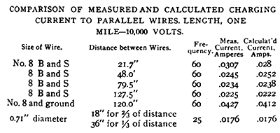 |
(3) The fall of potential around the wires was noted by tests made with spark-gaps. The wires 48 inches apart were connected to the high-voltage terminals and a spark-gap was placed between two idle wires also 48 inches apart, placed about 21 inches below the first wires. A spark-gap consisting of brass terminals with a 4 inch radius was placed between two idle wires. When the gap was 1-32 inch the sparking began when the e. m. f. from the raising transformer was 26,000 volts. A gap of 1-32 inch requires an e. m. f . of 2,200 volts to produce sparking. When the spark- gap was made 8-32 inch (equivalent to 12,000 volts) the sparking began at 103,000 volts from the raising transformer. At intermediate points there is a fair proportionality between the spark-gap and the e. m. f.
In another test a spark-gap was placed between one of the idle wires and the adjacent wire of the live circuit. When the spark gap was inch (equivalent to 6,000 volts) the spark passed when the e. m. f. was 17,500 volts, and when the spark was made 1/4 inch (equivalent to 12,000 volts) the sparking began at 33,000 volts . When the gap was 1/8 inch (equivalent to 16,000 volts) sparking began at 41,000 volts. When the gap was ½ inch (equivalent to 20,000 volts) sparking occurred at 49,000 volts. The e. m. f. did not differ greatly from a sine wave. These tests have an important bearing in connection with the running of telephone and other circuits adjacent to high potential wires. It is essential that the wires of a high- potential circuit be spiraled so that each wire sustains the same relation as every other wire to the second circuit, in order that the effects of static induction may be neutralized.
(4) The effect of the size of wire upon the loss was investigated by running a pair of No. 28 brass wires 0.0126 inch in diameter and then replacing it by large rubber-covered wires. The rubber-covered wire was No. 7 B. & S. gauge 0.144 inch in diameter; the outside diameter of the rubber covering was 0.3 inch and the diameter over the braid was 0.35 inch. In each case measurements were made upon another circuit which was unchanged during the different tests, and thus served for comparison. The loss is greatly decreased when the rubber-covered wire is used. The loss on the rubber- covered wire, however, increased considerably after the voltage had been raised and the rubber had broken down, thus permitting the current to pass freely to the outer surface of the insulation. It is quite probable that the loss would increase as the insulation became defective, until it was nearly equal to that of a wire having the same total diameter.
(5) The effect of the current in drying the surface of the insulators was illustrated in a test made during a rain. Upon applying 45,000 volts to a circuit the wattmeter indicated 116. After four minutes the deflection had decreased to 72, the current remaining the same. The e. m. f. was then increased to 60,000 volts, the wattmeter deflection increased to 155, and at the end of three minutes it had fallen to 138. The current was one-third greater than at the lower voltage, but remained constant while the wattmeter changed. The rain continued during the test, which shows, therefore, that the condition of the insulator is materially improved by the presence of the current.
(6) It was noticed that when there was a break- down upon the line and the current passed suddenly between wires over the surface of the cross-arm that there was a sparking between the terminals of the ammeters in the high tension circuit across the surface of the instrument. This was further investigated by placing in circuit a coil of low resistance through which 1 ampere would be sent by about 12 volts at a frequency of 125. A spark gap was placed in shunt to this coil. A 2 inch spark-gap was also placed between the line wires. The voltage of the primary was gradually raised until at 35,000 volts the current passed across the spark- gap between the line wires. A spark also passed across a gap of 3/8 inch, shunting the small choke-coil . This test shows the remarkable suddenness of the rush of current when the short-circuit occurs due to the breaking down of the spark gap on a high-voltage circuit. This phenomenon was observed by Mr. Mershon in choke- coils used in connection with lightning arresters at Telluride.
Running tests were made on four lines in multiple at high voltages. Each line consisted of two wires 1,040 feet in length held by 26 insulators. The insulators were of various types of glass and porcelain, some of the ordinary form and some under hung. For hours at a time 100,000 volts or slightly more were kept upon the line. For about six weeks voltages ranging from 70,000 or 80,000 to 100,000 volts were kept on the lines for about eight hours a day. When there was rain the line would short circuit and the voltage had to be reduced. During a driving rain storm 48,000 volts was kept on the lines, and it may have required a considerably higher voltage to have caused short- circuiting.
(7) A high-tension wattmeter similar to the Thomson watt meter at Telluride was used. To correct the wattmeter for the errors caused by charging current in the shunt resistance, a con denser was placed in parallel to the shunt circuit of the watt meter. This condenser should be so adjusted that the current through the shunt circuit of the wattmeter is the same that it would be if there were no condenser and the shunt resistance had no capacity. This permits the capacity current in the circuit to be shunted round the wattmeter by the condenser. The condenser in shunt to the wattmeter was capable of adjustment, and by varying its capacity the deflection could be made positive or zero or negative when current was delivered to a constant load. The proper adjustment was made by taking a comparatively low voltage, at which the charging current was very high in comparison with the loss, so that the loss was nearly negligible, and adjusting the wattmeter to indicate zero. At higher voltages, when there was a considerable loss, the error with this adjustment would be inappreciable. Certain variations with temperature and humidity were noted which would be explained by a variation in the capacity of the resistance, causing a variation in the charging current to the shunt circuit of the wattmeter. The high resistance for the shunt circuit was wound upon fuller board plates containing brass stiffening pieces. Tests were made upon individual plates by measuring the capacity between the wire and the supporting strip of brass, and it was found that the capacity and the insulation resistance both varied with the amount of moisture in the fuller-board insulation. In order to prevent variations of this kind, subsequent resistances were wound upon glass plates, which seems to be a very satisfactory form of construction.
TESTS AT NIAGARA.
Some measurements have been made upon the Niagara-Buffalo transmission line. There are two circuits of three wires each, one of the which was in service and the other was available for tests. Each circuit consists of three cables each of 350,000 c. m., approximately 0.7 inch in diameter. The cables are run on porcelain insulators, and are on the same cross-arm. Adjacent insulators are 18 inches apart and the circuit is spiraled, so that each of the three wires occupies the middle position for a third of the distance. Current from one of the 5,000 h. p. generators was applied to the line through a raising transformer, by which the voltage can be increased by small steps to 100,000 volts.
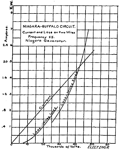 |
Measurements were made between the various pairs of wires, i . e., 1 and 2, 2 and 3, and I and 3; the current was found to be practically the same in each case; the loss on one of the circuits was slightly greater than that on either of the other two, on which the losses were about equal. The accompanying curve shows the measurements of current when two wires were connected and the measurement of loss; the latter measurements were made upon one pair of wires up to about 26,000 volts and then upon a second pair. The results are given in Fig. 4.
On another day measurements were made of the resistance between each wire and the ground, and corresponding measurements of loss were made by placing the high potentials between each wire and the ground. The measured loss was somewhat greater than the loss calculated by using e. m. f. and the measured resistance. In these measurements, at voltages from 13,000 to 23,000 volts, the power factor calculated from the current and wattmeter measurements, varied from about 4 per cent. to 6 per cent., so that a very small charging current in the watt meter would produce a considerable error in the reading suspended by light strings successively at 6 inches apart, 14 inches apart, and about 25 inches apart, the distance varying from 24 inches to 27 inches. The power factor of the measurements made above 100,000 volts is about 95 per cent., and is over 80 per cent. above 70,000 volts. There can be but little error in the wattmeter due to charging current in the resistance at these power factors. The measurements on the Buffalo line were made by the writer. Those on the fine wires were made by Mr. E. M. Tingley, who conducted the tests at East Pittsburg, and rendered valuable assistance in the preparation of this paper.
Some measurements were made upon a pair of fine wires, in which the wires were placed at different distances apart. No. 31 B. & S. gauge spring brass wire 0.0089 inch in diameter was used. The length of the parallel wires was 774 feet. They were suspended by light strings successively at 6 inches apart, 14 inches apart, and about 25 inches apart, the distance varying from 24 inches to 27 inches. The power factor of the measurements made above 100,000 volts is about 95 per cent., and is over 80 per cent. above 70,000 volts. There can be but little error in the wattmeter due to charging current in the resistance at these power factors.
The measurements on the Buffalo line were made by the writer. Those on the fine wires were made by Mr. E. M. Tingley, who conducted the tests at East Pittsburg, and rendered valuable assistance in the preparation of this paper.
POWER TRANSMISSION PLANTS IN OPERATION.
Beginning with the plant at San Bernardino and Pomona, which began operation in 1892, using 10,000 volts and transmitting 30 miles, a constantly increasing number of plants have been installed operating at 10,000 or 15,000 volts. In some cases there has been little or no trouble experienced with the transmission lines, while in other cases the experiences have been less satisfactory. The principal trouble seems to have been a poor grade or an insufficient size of porcelain insulator. In other cases the insulators, sometimes porcelain and sometimes glass, have given almost perfect satisfaction.
The superintendent of a power company which has been running fifteen months with about 15,000 volts, reports that they "have had absolutely no trouble whatever of an electrical nature." Some insulators were broken because they had been used as targets by small boys or hunters, but only the outer petticoats were broken, and no short-circuits occurred, although in some cases insulators were in use for months with most of the outer petticoats chipped off. The distance of transmission is 12 miles. Porcelain insulators are used.
In another plant which has been in operation about a year and a half employing 15,000 volts for a distance of nearly 30 miles, there have been but three shut-downs on account of line difficulties. These were due to the breaking of insulators at a point where the line was spiraled. In one case the repair was made in half an hour, and in the other case a few minutes' interruption to the service was sufficient for repairs.
The line is regularly patrolled, and if a defective insulator or pin is found, the generating station is notified by telephone and the line is shut down for a few moments at noon. In one case two poles were burned by a defect in the insulators on the top of each. The poles burned to the ground, leaving the wire hanging clear without any one at either the generating station or substation being aware of the fact.
Troubles have arisen on some lines by the burning off of pins by the passage of sparks from the outer edge of the insulator to the pin. These sparks make small holes in the pin no larger than a needle point, but after continuous sparking for some time the pin becomes entirely charred. An iron pin suggested itself as a remedy, but additional strains and liability to break-down are liable when a conductor is placed within the insulator. The burning off of pins has occurred where small porcelain insulators are porous and the outside glaze is imperfect, while the glaze on the inside is good. When the porcelain is filled with water the current readily passes through it to the lower rim of the insulator and then sparks across to the pin. In one place which has been running for about three years some 250 pins burned off. The early insulators have been replaced by larger and better ones, and this defect has disappeared.
A 10,000 volt-line which runs for a dozen miles or more within a few hundred yards of the Pacific coast has burned cross-arms on nearly every pole. The cross-arms near the ends of the line, which are away from the coast, are not burned. Usually the burning appears as a mere blackening of the cross-arm for a short space between the insulators, on one side of the arm. In some cases the charring is deeper, and appears on both sides. The side on which almost all of the burning occurs is the one toward which the winds come from the ocean, bearing the mist of salt water. The wire shows discoloration, and the iron braces for holding the cross- arms are in a few cases eaten through. Moreover, the cross-arms were green and full of sap when erected. The early porcelain insulators were porous, and have now been replaced, and the pins are of iron. The charring has ceased almost entirely since the new porcelains were put up.
It may be observed that in the plants which are herein referred to and in the experimental tests, no mention has been made of insulators with cups containing oil for reducing the surface leak age. Insulators of this kind were used in the Frankfort-Lauffen experimental transmission line at 30,000 volts. Practically, however, the surface insulation is adequate without oil cups and the principal duty of the insulator is to prevent the current passing over the surface and jumping to the pin or cross-arm, a matter with which the oil would have nothing to do.
Telephone lines are in use in a number of plants placed on the poles which carry the transmission wires. The telephone lines are usually placed some distance below the transmission wires and are crossed at frequent intervals. The telephones in general work very satisfactorily.
