[Trade Journal]
Publication: Street Railway Journal
New York, NY, United States
vol. 15, no. 7, p. 437-440, col. 1-2
Overhead Line Construction II.
BY ALBERT B. HERRICK
THE INSULATION OF THE FEEDER
In addition to the insulation covering on the feeder wire, a second insulation should be introduced between the feed wire and its mechanical supports. The materials generally used for this purpose are porcelain, glass and compounds of mica and shellac, rubber and asbestos. The mechanical properties of this insulation should be such that it will stand strains without fracture, and that the surface will not absorb moisture. Glass or porcelain is generally used for No. 000 feeders or smaller, but for larger feeders with long spans, exceedingly strong insulators should be selected, especially where it is also necessary to use an iron pin. Porcelain has been greatly improved in strength during recent years, and the present method of firing it in the kiln has thoroughly vitrified the body of the insulator, still leaving it tough. The method of testing a porcelain insulator, to determine whether vitrification has taken place, is to break it and apply analine ink to the fractured surface of the broken portions of the body. If, after washing, a general discoloration of the porcelain is found, it has not been properly fired.
 |
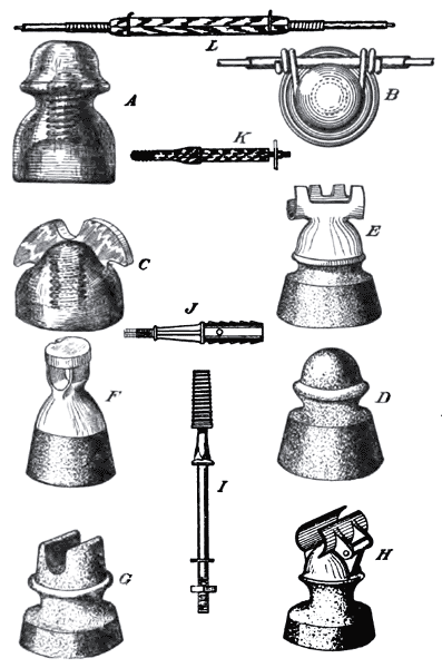
| Forms of Feeder Insulators. |
In the saddle form of insulator, shown at C, with butterfly wings, the portion of the insulator where the wire rests should be provided with rounded edges so as not to abrade the wire, if there is any movement of the feeder due to temperature changes. The flarings of the petticoat should not be too wide to allow water to spatter under them from the cross arm, or too narrow, as this condition invites insects to make cocoons and nests in them. Where a flaring petticoat is used, the top of the cross arm may be rounded and the edge of the insulators made helmet-shaped, so that the drip shall fall outside the cross arm, but these considerations are more pertinent in high tension transmission work.
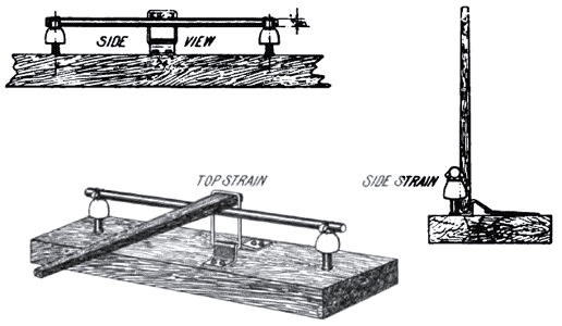
The strength of insulators can be tested as follows: Place two of the regular pins 24 ins. apart in a wooden beam, 4 ins. x 6 ins., and tie down into the top of the side groove of the insulator a 5/8-in. rod of iron 28 ins. long. A strain by a lever that will give a permanent set to this rod should not fracture the insulator. A test should be given for both top and side strains. The method of making this relative strain test is shown herewith. No copper line can withstand such strains to an insulator as these tests impose. The strain of the copper conductor is a limiting mechanical factor beyond which it is not profitable to increase the strength of the pole line.
The composite insulator, which is formed of a metallic saddle for the feeder and a metallic bushing for the pin, is a form of insulator largely used. These two metallic parts are held together and insulated from each other by insulating material which is generally molded into place under heat and great pressure. The desirable qualities in the composition used are that it have sufficient mechanical strength and that the strength be maintained when the temperature of the insulator has been raised to 150 degs. F. The worst fault of these composite insulators is that they become plastic in warm weather and yield to conductor strains. This composite insulating material should not be affected by rain so as to dissolve any of the substances in the composition, as a roughened surface will hold dirt and produce a leaky surface.
 |
| Device for Testing Stength of Feeder Insulators. |
Where the line passes through trees it must be protected from contact with the latter, as the movement of the branches by the wind abrades the insulation of the wire.
For cases of this kind the split wooden sheath, shown in "L" on this page, is often used. This should be held firmly in position so as to not slip along the wire, but the really best protection, where it is possible, is to pull the feeder away by guying it to another limb. If a split porcelain insulator is used to enclose the feeder and the guy twisted around the porcelain insulator and some tension put on it to an adjacent limb, the tree and the wire are both free to move without any considerable strain.
·
·
