[Trade Journal]
Publication: Street Railway Review
Chicago, IL, United States
vol. 5, no. 2, p. 73-79, col. 1-2
OVERHEAD CONSTRUCTION IN CHICAGO.
"Not How Cheap, But How Good."
While Chicago has been behind the times, so far as electric railways are concerned, its slowness in admitting the trolley has given the electric railway industry time to develop, so that the experience of the many hundreds of roads already installed in various parts of the country, is available to guide those who are engaged here in the work of construction. It has been the aim of the three companies whose work is being considered in this article to put up the best and most substantial overhead work that money can buy. So few companies construct overhead lines with this single purpose in view that a review of what is being done in Chicago will be of interest on this account, if no other. A number of special problems came up also in connection with each company's work, arid the solution of these will be noted. The work here described has been carried on during the past seven months by the North Chicago Street Railroad, the West Chicago Street Railroad and the Chicago City Railway. The power houses of these companies each cover an immense territory, and consequently the feed wire construction is very heavy.
NORTH AND WEST SIDES.
The North and West Chicago Street Railroads have had J. R. Chapman in charge of the electrical work. Under him is J. S. Hill supervising the overhead work on the west side and C. E. Collins on the north side. The work on the north side is now nearly completed, with the exception of that nearest the heart of the city.
| |||
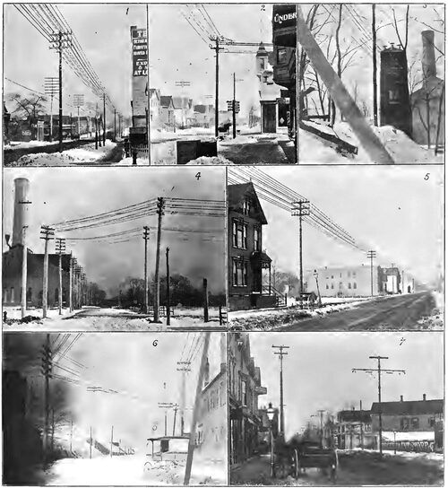
| Overhead Construction. -- North Side, Chicago. 1. Specimen Feed Line, 2. A Neat Corner, 3. Tower Leading to Tunnel, California Avenue Power Station, 4. Approaching California Avenue Station From the West, 5. Clybourn Avenue Trolley and Feed Line, 6. Power-House Approach. Return Feeders Running Into the Ground at Right, 7. Lincoln Avenue Center Poles. |
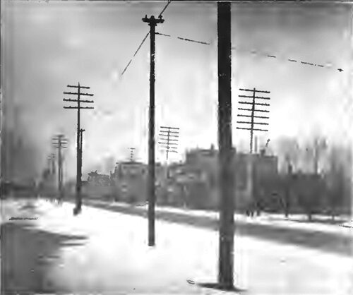
Iron pole construction is used throughout by these two companies, with the exception of a few feeder lines on unimproved streets. The standard side pole arrangement is shown in the engravings. The poles are steel tubular, 7 inches inside diameter at the bottom, 6 inches in the middle and 5 inches at the top. Andersons' strain insulators are bolted directly to the strap around the pole top. The eyebolt on this form of strain insulator allows of a slight tightening of the span wire, although in general it is calculated that the span wires will never need tightening. The insulating material for the trolley hangers was furnished by A. & J. M. Anderson, the metallic coverings and ears were made by the street railroad company, and the trolley wire clips are from the New York Electrical Works. The poles, instead of being set in the ground direct, are put inside an iron cylinder or sleeve, which is a little larger than the base of the pole and comes up slightly above the street surface. The space between the pole and sleeve is filled by pouring in hot pitch. The idea is to prevent the poles rusting in the ground, especially near the surface. The sleeve is, of course, set in concrete. Trolley sections are one mile long, and feeder taps are made five times to each mile. A Westinghouse lightning arrester is placed on each section. The plan of a feeder tap pole with lightning arrester is shown among the diagrams. It will be noted that track feeders are carried on the poles alongside the trolley feeders, and that at every pole at which the trolley wire taps the feed wire a corresponding tap is run down through the pole to the rails. The ground connection of the lightning arrester is made to this track tap. Guard wires are used only in places where telephone or telegraph wires are specially liable to drop. The standard center pole construction of these companies is also shown. Here, too, the principle of double insulation prevails. A short span wire is stretched between the end of the bracket and the pole. At the end of the bracket it is tied around a porcelain insulator, and at the pole it is tied to the eyebolt of a strain insulator. The advantages of this arrangement are obvious to the electric railway man who knows the advantage of a flexibly suspended hanger and the trouble arising from short circuits when the trolley pole comes off and makes connection between an uninsulated bracket and the trolley wire. A side bracket pole is also show n for use along Twelfth street boulevard, where the boulevard occupies the center of the street and the tracks run along each side. Where a trolley line crosses under the elevated structure, a wooden trough is built and the trolley wire put between two angle irons as shown. This will make it practically impossible for a trolley pole to fly up and hit the structure.
| |||
| Chicago City Railway Standard Construction. |
| |||
| Overhead Entrance to California Avenue Power Station. |
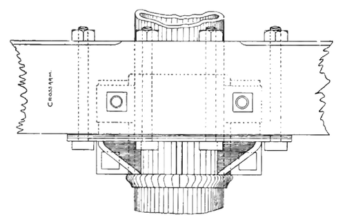 |
| Red Wood Cross Arm for Lead Pole. -- Chicago City Railway. |
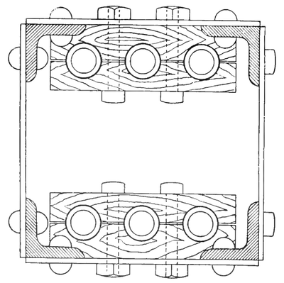 |
| Section of Box Pole for Feeders. |
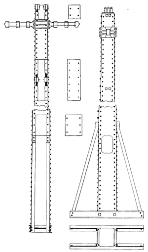 |
| Box Poles Leading From Underground to Overhead Feed Lines -- West Side. |
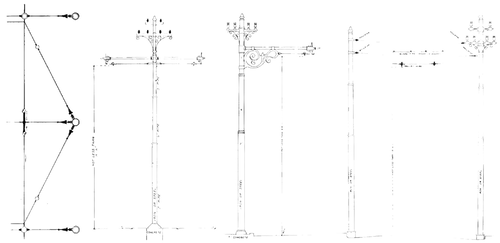 |
| Standard Span and Bracket Construction North and West Sides. |
The Lake street trolley which will run under the Lake street elevated from one end to the other will have two methods of construction. Where the structure is low, the hanger will be put in a short section of trough under each girder. Where the structure is high, a span will be stretched between the posts as in ordinary side pole work. With the first mentioned arrangement a special hanger is used.
We will now turn our attention to the feed line construction which is of interest, because of its weight and because of several special problems which have come up. The feed cables, of which the majority are 500,000 circular mil, are carried on center bearing insulators made by Andersons and consisting of a metallic top fitting over a cap of "Aetna" insulating compound. They are screwed onto a pin consisting of the same insulating compound surrounding an iron bolt. The return feeders are put on galvanized iron insulators of the same shape.
These return feeders have an insulating covering. Where wooden poles are used the cross arms are all double.
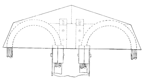 |
| Hood Over Box Feeder Poles. |
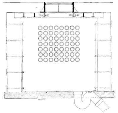 |
| Manhole, West Side Conduit. |
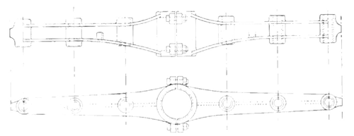 |
| Standard Iron Cross Arm, North Side. |
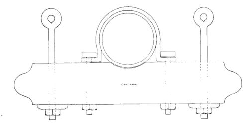 |
| Cross Arm for Double Span at Railroad Crossings, City Railway. |
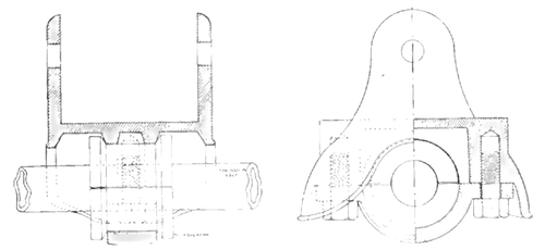 |
| Cast Iron "Dunce" Cap for Feeder Insulaobs Under "L" Structure. |
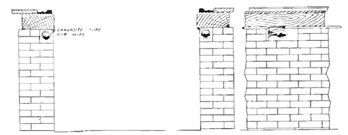 |
| Pit Lighting, North Side. |
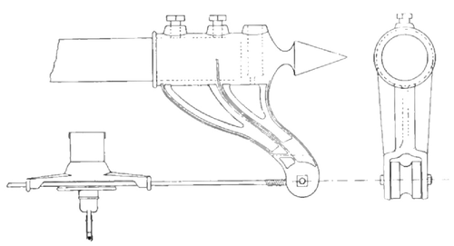 |
| Flexible Bracket, With Insulated Span, North Side. |
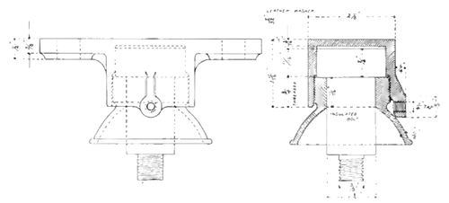 |
| Special Trolley Hanger for "L" Structure. |
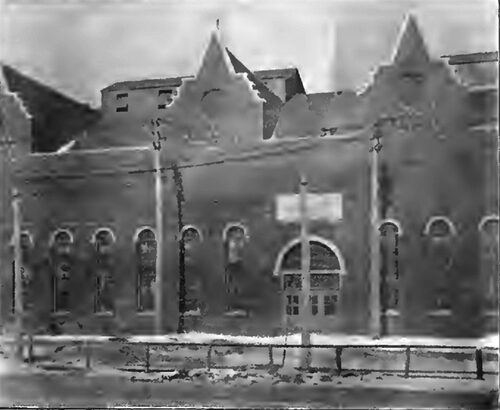
Double insulation has been the policy on all work. Where feeders turn a corner they are dead ended and two strain insulators put in. At the power plant at California avenue and Roscoe street. which supplies the northwest part of the city, about half the feeders cross the river which is to be a navigable stream at this point. A tower has been erected on the east bank of the river. The feed lines enter this tower and are led through a subway passing under the river and into the basement of the power house on the west side of the river. The track feeders as they leave this power house are run in wooden troughs for a distance of about a quarter of a mile. The feed lines then diverge so that there is room for the track feeders on the poles. The track feeders when run under ground are 1,000,000 circular mil stranded and tinned bare copper cables.
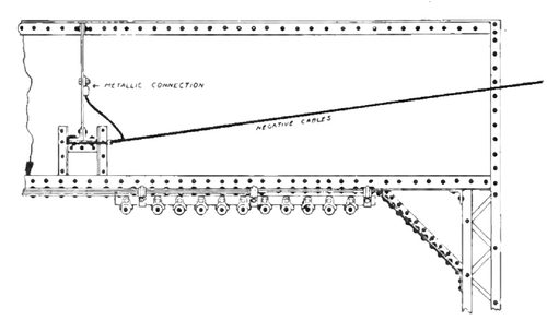 |
| Approach Connection of Negative Feeders to "L" Structure. |
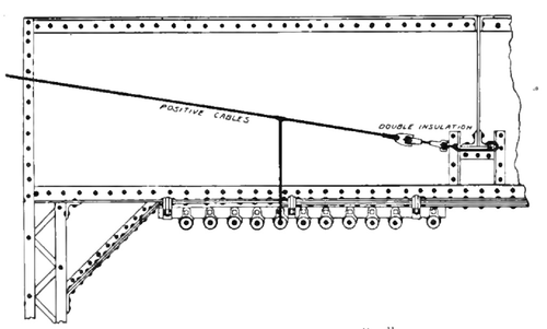 |
| Approach of Positive Feeder to "L" Feed Line. |
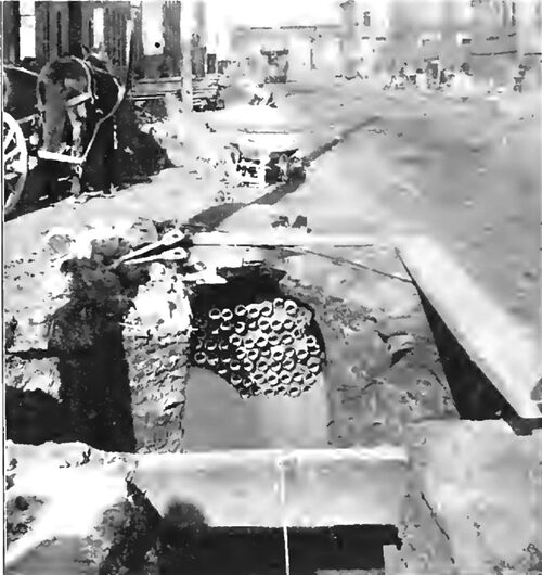
The feeders from the West Chicago Street Railroad power house, at Western avenue and Washington boulevard, are taken for a distance in an underground conduit. Indeed, when it is stated that this is to be the largest railway power plant in the United States, and that it is in the middle of a thickly settled territory, it will be understood that it was not feasible to hang so much copper in the air as the output of this station would require. This conduit extends north from the power station, two blocks on Western avenue to Lake street, where the feeders come to the surface and are carried east and west on the Lake street elevated structure and north on a pole line. One of the heaviest trunk feed lines is carried under the elevated structure. The conduit extends south from the power station about a mile and a quarter, a few feeders being brought to the surface at each intersecting trolley line. Feeders are brought to the surface in iron box poles. Water is kept out of these poles by an iron hood, as shown.
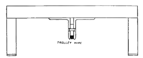 |
| Trolley Holder "L" Crossing. |
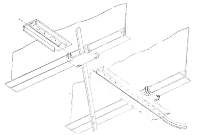 |
| Trolley Crossing Under "L" |
The conduit was laid by the National Conduit Manufacturing Company. The ducts are 2 % inches, inside measurement. They are of short sections of sheet iron, laid in concrete and lined with cement. Fifty-six ducts leave the power station, half going north and half south. Cables of 1,000,000 circular mils will be used in all ducts.
Under the elevated structure the feeders will be hung in porcelain insulators. These porcelain insulators are supported by a cast iron hood, which will keep the insulator dry. The hoods will be fastened to wood beams. The method of approaching and leaving the elevated structure with positive and negative feeders is shown, as is also the arrangement of insulators and hoods where a large number of feeders leave the elevated at Ashland avenue, and there is not room to use the common method.
SOUTH SIDE.
The Chicago City Railway electrician, G. W. Knox, has had charge of this company's overhead work, and has aimed to put up as thoroughly reliable a construction from an electrical and mechanical standpoint, as money and intelligence can make. He has received many compliments on the character of the work.
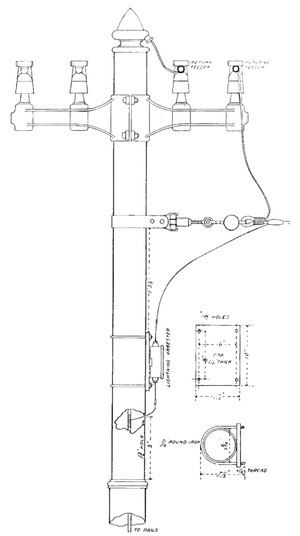 |
| Feeder Tap Pole, North Side. |
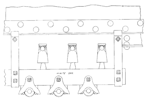 |
| Leaving "L" at Ashland Avenue. |
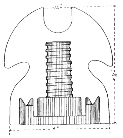 |
| Special Feed Insulator.--Chicago--City Railway. |
Side pole construction is used throughout on this road. The poles are steel tubular 7-6-5 inches, set directly in concrete. Lattice poles are used at curves. Medbury strain insulators are used in the span wires, and the trolley hangers were made by the Wallace Electric Company. The clips, overhead crossings and line breakers, of Mr. Knox's design, are made in the City Railway brass foundry. Three insulations are put between trolley wire and poles. In addition to the trolley hanger and strain insulator, a wood insulator is put around the bolt where the span wire ties to the pole strap. Another special feature on this road is the arrangement of overhead curves where the curve is but seldom used, and cars pass the main line in regular service. Instead of putting in a switch which demands the conductor's attention every time it is passed, the main line is left unbroken, and the curve wire is brought along parallel with the main line for a short distance. This necessitates changing the trolley when going around the curve, but this arrangement is only put on curves that are seldom used.
In feed line construction, no cables larger than 350,000 circular mils are used, as it is thought that the sag and trouble in maintaining a neat and substantial line with larger cables, more than balances the advantages of their greater size. The main pole line of this company runs through an alley between State street and Wabash avenue, so that wooden poles are used. Glass insulators, designed by Mr. Knox, specially for this work, are employed. They are shown herewith. Where feeders are carried along iron side poles, wood cross arms are used. This is a manifest advantage as to insulation, and it would take a close observer to notice the difference in appearance between it and the iron cross arm.
| |||
| Western Avenue Conduit Under Construction. |
For a return circuit, reliance is placed entirely on heavy bonding, except near the power station, where supplementary cables of 1,500,000 circular mils area are laid in the ground between the tracks. Each rail is double bonded with No. 0000 Chicago rail bonds, except in the outlying districts, where smaller bonds are used. Wires are run around all switches and special work, to insure continuity of track circuit. At boulevard crossings, the feed wires are run underground in pump logs.
All the work described in this article was designed by men who have had years of experience in the business, and who were able to profit by the lessons taught by the electric railway construction of former days. Although it is by no means completed as yet, it is far enough along so that the general plan of construction can be studied by those interested. The work on the northwest side is nearly finished. That on the south and west sides will be completed during the next season. Work has been pushed constantly, in spite of the severe winter.

