[Trade Journal]
Publication: Street Railway Journal
New York, NY, United States
vol. 15, no. 10, p. 627-632, col. 1-2
OVERHEAD CONSTRUCTION IN CHICAGO
The overhead structure in Chicago is simple in design, is well put up and is durable. There has been no attempt at over-ornamentation of poles, but the entire structure is as inconspicuous as is possible to obtain. Iron poles weighing from 900 lbs. to 1200 lbs. are used, with wood poles through the "alleys" between streets.
| |||
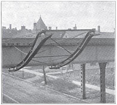
| Fig. 1. Overhead Wire Bracket for Surface Lines on Elevated Railway Structure |
| |||
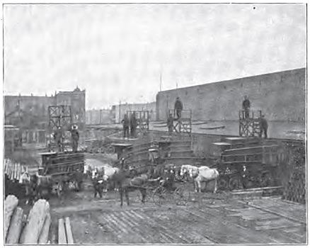
| Fig. 2. Construction Wagons, Chicago City Railway |
| |||
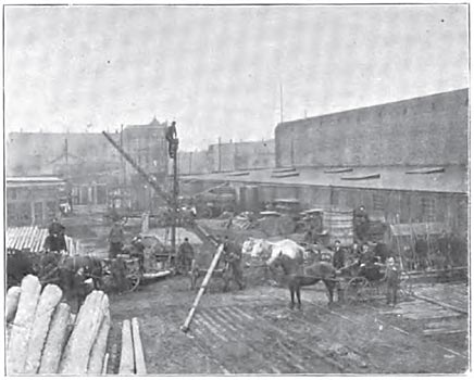
| Fig. 3. Pole-Raising Wagon, Chicago City Railway |
The standard trolley wire of the Union Traction Company is No. 0 hard drawn copper, and the standard guard wire is No. 6 silicon bronze. In the business district silicon bronze is also used for span wire, while in the suburbs 5-16-in. stranded galvanized wires are used. Aetna insulation is used throughout with line material made by Albert & J. M. Anderson, the originators of the Aetna insulation.
The Chicago City Railway Company formerly used No. 0 trolley wire, but now uses No. 00, both because of its mechanical strength and because of its assistance in helping out the general feeder distribution system. A span wire consisting of 3/8-in. seven strand galvanized iron cable is used at all places, but there are no guard wires on the Chicago City system, as they are believed to be a menace to life and property, and in all cases where they were formerly installed they have been taken down.
| |||
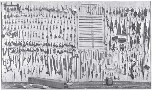
| Fig. 4. Overhead Line Material, Past and Present Practice, Chicago City Railway |
| |||
| (Enlargement of Pin-Type Insulators in Fig. 4. Not in Original Publication) |
| |||
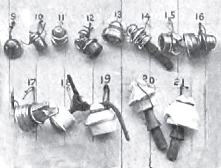
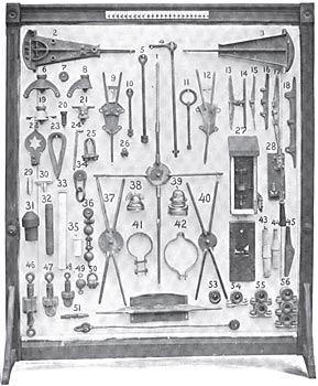
| Fig. 5. Overhead Line Material, Present Standard, Chicago City Railway |
| |||
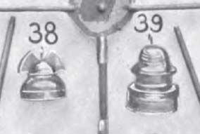
| (Enlargement of Pin-Type Insulators in Fig. 5. Not in Original Publication) |
In the engravings pages 630-631 are shown all types of line material ever used on the Chicago City system, the engraving, Fig. 5, showing the material selected as the company's present standard. The following description of these standard pieces will well illustrate the latest development of overhead line material and the reasons for some of the mechanical details which have been devised.
Brass is employed in all of this material with one or two exceptions, and iron is in no place made to join iron, even where it is necessary to let an eye bolt, for example, into a brass core. Malleable and other iron material in overhead work has been practically abandoned because of its rapid deterioration and loss in cross section by rust, and also because it was found that the rust spread over the insulating material, causing short circuits. Brass is not affected by the weather, and when broken or discarded for any reason can be melted down, and is found cheaper in the long run than iron.
While the high insulating qualities of rubber are recognized, particularly in places where it can be kept free from air and moisture, it is found in the Chicago City Company's practice that on exposure the surface cracks, and after a short time these cracks become filled with coal dust, soot and other particles which serve to conduct the current around and across the insulation. The company's standard insulating material, therefore, is red fibre for switches, the Aetna being regarded as the best in use. Three insulations between the trolley wire and the ground are made in all cases, the first being a fibre spool in the pole band (Fig. 5, No. 41); the second, a similar insulating spool (No. 50), attached to the first by a 3-ft. strand of galvanized iron wire, and the third, the regular straight line hanger (No. 19). This consists of an insulating bolt (No. 20), and a wood piece (No. 57).
In splicing two pieces of trolley wire, their ends are brought to the splicing ear (No. 17), and bent up therein through holes, leaving a smooth run for the trolley wheel. No solder is used either in splicing or attaching straight line hangers, but only for connecting feeder cables. The heat necessary for the use of solder is found to anneal trolley wire, weakening it and making it liable to crystallization and breakage.
When trolley wires are strung in ordinary summer weather, or when the temperature runs about 75 degs., a sag of 8 ins. or 10 ins. is allowed in all spans of from 115 ft. to 120 ft., but in cold weather from 5 ins. to 6 ins. of sag only are allowed. The average height of the trolley wire above the ground is from 19 ft. to 19 ft 6 ins., except a railroad crossings, where it is from 22 ft. 6 ins. to 23 ft. A method of supporting the trolley wire from the elevated structure at a point where it passes over a railroad track is shown in Fig. 1.
Clinch ears are employed, as they are not likely to let the wire down, while on curves they will move slightly on the wire if the trolley pole catches in strain wires, and thereby prevent the pulling down of the line, as might sometimes occur.
Tubular iron poles are in all cases employed in new construction, lattice poles having been discarded. The standard straight line pole consists of three sections, 7 ins. 6 ins. and 5 ins. in diameter, which weighs from 850 lbs. to 900 lbs. Corner poles are 8 ins., 7 ins. and 6 ins. in diameter, and some extra strain poles weigh as high as 1200 lbs. In setting the pole, its base is treated by a preservative paint, composed of tar and other mixtures. It is then imbedded in concrete to a depth of 6 ft. or 7 ft., and the bottom rests on a hard wood board 12 ins. long 1 3/4 ins. thick. At the street surface an iron thimble 12 ins. long encircles the pole and is imbedded in the concrete. The hole of this thimble is an inch larger in diameter than the pole which it contains, and when the latter is set in position, the space is filled with cement up to a flange in the thimble, so that a slanting roof of cement is made all around. Cement is preferred to tar, as the latter is apt to shrink and crack, thereby allowing water to reach the iron and rust it.
Where the poles are rusty, they are first scraped with steel brushes and painted. The first coat is a red paint, which is followed by a coat of graphite. A coat of paint lasts usually about three years, except on lines near the Chicago River, where the gases from the foul water in the river cause the poles to deteriorate rapidly. It is worthy of note also that the trolley wire on lines adjacent to the river oxidize much faster than others, and a bright copper wire tarnishes in half an hour after being strung in this neighborhood.
Poles are repainted every three or four years, and are stated to have a life of twenty or thirty years, the annual depreciation being regarded as about 3 ½ per cent to 4 per cent, while cedar poles are said to depreciate at the rate of 6 ½ per cent to 7 per cent per year, having a life of only fourteen or fifteen years.
An iron cap is placed at the top of each pole, and there is an ornamental cast-iron ring at each joint. Ordinarily, the pole band (Fig. 5, No. 41) is placed 10 ins. from the top of the pole. On some lines the poles carry an ornamental hanger for supporting electric lamps, these being installed and maintained by the city. Cross arms are of wood, with supporting iron brakes.
After trying nearly all kinds of trolley line switches on the market, a standard (Fig. 5, Nos. 9 and 12) has been adopted. No. 9 shows a "Y" shaped, and No. 12 a right-hand switch, with the corresponding left-hand. No. 1 is an insulated cross-over. This is composed of a section of red fibre 1 in. x 3 ins., an din adjusting it, it is not necessary to cut the trolley wire, as the wires of both lines can be led over the insulated portion, one above the other. A burn-out has never occurred with this style of cross-over on the Chicago City system. In Nos. 37 and 40 are shown two forms of live cross-overs; No. 40 is a design for ordinary right-angle crossings and has a small circle, while for the acute crossing, No. 37, the circle is larger. The section insulator shown in No. 52 is of the same style of construction as the insulated cross-over, but has a hood to protect the fibre from the action of sleet and water.
At all section insulators and at insulated cross-overs, metal targets, shown at No. 22, are employed. These are in the shape of an incandescent lamp and are painted red with a white star in the center. They are clamped to the span-wire or trolley wire at the section, and at these points the motorman is required to throw off the current in passing. This is in order to prevent the fibre from being injured by the arcing which would be caused were the run made with full current.
Lightning arresters are, as a rule, installed at every half-mile of double track or every mile of trolley. These are placed on the poles and grounded. The Garton type of arrester is mostly employed, although experiments have been made with all the commercial types. The arresters are frequently inspected, and in many of them a sheet of paper is inserted between the points, which is often found to be perforated, showing the good work of the arresters. Yet with all the precautions the atmospheric currents sometimes get by and damage the motor armatures or burn out the insulation of the underground lead-covered cables. This has occurred to the underground cables where arresters were placed on each side of the point at which the cables were led from the underground ducts up into the line.
Return feeders are in two sizes, one a 350,000 c.m. cable and the other a 211 600 cm. cable. The 500 000 cm. sections are regarded as too heavy, and hard to maintain on poles. Considerable cable is employed with a jute insulation treated with tar, resin, etc. The company's standard, however, is the lead-covered cable with rubber insulation, of which there has never been a foot lost from the burning out of the insulation. The cost, however, is about 25 per cent more than the cables in which other insulation is employed.
The underground cables are enclosed in conduits of vitrified material, and both single and multiple ducts are employed. The four-duct sections are made in 6-ft. lengths.
In installing the return circuit cables on all sections within 2 or 3 miles of the power houses, 25 per cent to 30 per cent more copper is employed in the return than in the outgoing section. This is regarded a necessary allowance for safety, and to prevent electrolysis in neighboring substructures, no complaint from this cause ever having been charged against the system.
In connection with the line material should be noted the construction and repair wagons employed by the electrical department. Four of the tower wagons are shown in Fig. 2, and as will be noted, these are very substantial structures built to accommodate a large amount of material. The box-like body is provided with a door at the rear and is equipped with shelves and receptacles for different classes of material. The illustration shows the wagons as they are just starting out from the electrical storage yard. A pole raising wagon and water tank for concrete mixing is shown in Fig. 3. This pole raising wagon is employed not only for raising poles, but also for loading and unloading the reels from the wagons illustrated in the large figure.
The high price to which copper wire has lately been carried has led to the serious consideration of aluminum as a substitute by a number of companies, but it may not be generally known that the largest actual installation of it so far made is on the new Northwestern Elevated Railway, which has purchased 150,000 lbs. of aluminum feeders, of which 75,000 lbs. are now in position. This wire is of 1,300,000 cm. sectional area, and is used uninsulated. It is supported every 9 ft. and anchored. The chief difficulty with aluminum in the past has been a question of welding, but this difficulty is said to have been entirely overcome in Chicago, though the process is a secret one. The metal is, of course, non-corrosive and is considerably cheaper than copper at present prices per unit of carrying capacity.
The Calumet Company is finally coming back to wood as an insulation material for hangers and strain poles. The bell shells are cast as in ordinary service, and the shell is then filled with a wooden block held in position by an ordinary bolt. The wood employed in the hangers and porcelain ears is first soaked in kerosene and then boiled in paraffine wax.
