[Trade Journal]
Publication: Electrical World and Engineer
New York, NY, United States
vol. 41, no. 26, p. 1089-1091, col. 1-2
Electric Power From the Hudson.
BY ALTON D. ADAMS.
SPIER FALLS, on the Hudson, at the foot of Mount McGregor, sixty miles south of Mount Marcy, where the river rises, and forty miles north of Albany, is to yield 32,000 hp for electrical transmission. In volume, this development of electric power is second only to that at Niagara Falls and at Sault Ste. Marie; in length of transmission it is probably not surpassed east of the Rock Mountains. Electric light, power and traction are to be supplied in Albany, Troy, Schenectady, at the General Electric Works and in many smaller places on the way. To effect this development of power the Hudson River is caught between Mount McGregor and another spur of the Adirondacks, raised fifty feet above its ancient bed, and then dropped through water wheels with a head of eighty feet. A stone dam 1,820 ft. long, about too ft. in maximum height above bed rock and containing 180,000 cubic yards of masonry is employed to raise the river level. This dam extends down to bed rock across the entire width of the river, and is anchored at each end in the solid ledge of the mountain side. Behind the dam a storage reservoir one-third of a mile wide and five miles long is formed, thus flooding the ancient river banks.
| |||
| Fig. 1. Getting An Air Compressor Ready. |
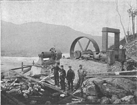
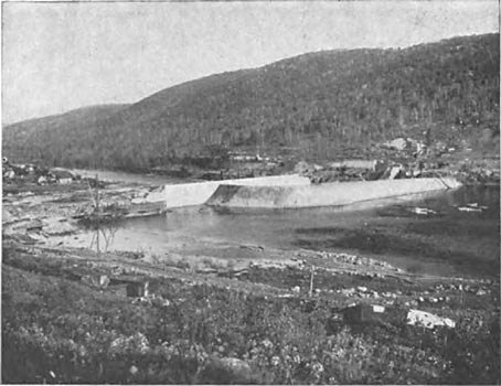
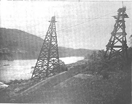
In this way the sights of roads, farms and dwellings will be covered. To provide for the construction of the masonry dam, a temporary one of earth, cribwork and stone was first built a little up stream from the permanent sight. An opening was left in the timber sections of the temporary dam at one side of the river so that the water was diverted from its normal course and a great portion of the old river bed at the sight of the permanent dam was left dry. Stone laid in concrete with close joints forms the regular construction of the main dam, though a larger proportion of concrete has been used on a small part of the work. The rule has been to carry the masonry of the dam down to bed rock throughout the entire distance across the river. This has made a large amount of excavation necessary and the cofferdam at one side of the old channel included an area of five acres during one stage of the work and had a maximum height of go ft. at one point. Both steam and compressed air have been used extensively on the work, the air compressors being operated by three-phase motors. These motors draw their energy from an electric power station at Mechanicsville, some 23 miles to the south. The new dam, anchored in the mountain ledges at its ends and sunk to bed rock entirely across the river, varies in extreme height according to the different depths at which this rock was found. At one typical section in its overfall part the dam is 59 ft. high above its bed, and 63 ft. up and down stream at its base. Considered as to its length the dam is made up of the river section, of 560 ft., the overfall of 820 ft., and the intake wall of 440 ft., making a total of 1,820 ft. between banks. The overflow portion of the dam must pass water at a very rapid rate during times of flood. At times of minimum flow at Spier Falls the Hudson discharges about 2.000 cubic ft. per second, but during maximum discharge the quantity of water goes up to as much as 50,000 cubic ft. per second. This great variation between high and low water discharge will no doubt be reduced by proposed storage dams at Indian and other lakes about the head waters of the Hudson, in which the State has become interested. The watershed of the Hudson River above Spier Falls has an area of about 27,000 square miles, and the mean, annual flow of the river at these falls is between 6,000 and 7,000 cubic ft. per second. Evidently, when storage works have brought the minimum discharge of water at the falls up to approximately the mean, annual rate, the amount of available power will be much larger than at present.
| |||
| Fig. 2. Changed Course of the River. |
Like the dam, the canal and the power house at Spier Falls are built on a natural rock foundation. The short canal is formed by blasting its course into the mountain ledge, and the sight for the power house has been provided by a similar process. The power house itself is one story, of brick, 70 ft. 10 in. x 392 ft. inside, and is located between the canal and the river, a little below the dam. Inside the power house in the direction of its greatest length is a 16-in. brick wall that divides the greater portion of it into two rooms each, 34 ft. 9 in, wide. In that one of these rooms which is nearer the canal are located the water wheels, and the shafts of these wheels extend through the 16-in. brick wall into the room where the electric generators are located. Beneath the floor of the wheel room is an opening 21 ft. 6 in. wide and extending its entire length.
| |||
| Fig. 3. Part of the Overfall Section. |
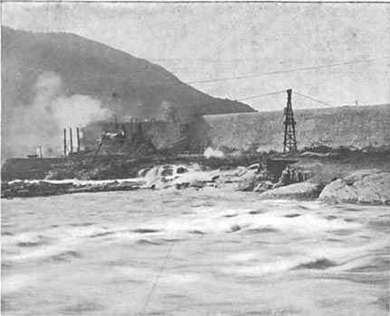
Across this opening are placed 36-in. box girders spaced on 14-ft. centers, and between pairs of these girders the water wheels are mounted. Beneath the floor of the generator room a series of arches connect the long chamber beneath the wheels with the space through which the tail water passes on its way to the river. Centers of the wheel and generator shafts are 16 ft. 9 in. above the low level of tail water, and the floors of the wheel and generator rooms are 9 ft. 9 in. above this tail water level. One crane mounted between the 16-in. interior and an outside wall sweeps the length of the generator room, and another crane supported in a similar way travels over the wheels.
From floor to the lower cords of the roof trusses the height in the wheel and generator rooms alike is 39 ft. 3 in. At one end of the power station a space extending across its entire width and about 46 ft. long is devoted to the step-up transformers and to the switchboard.
| |||
| Fig. 4. Site of the Power House. |
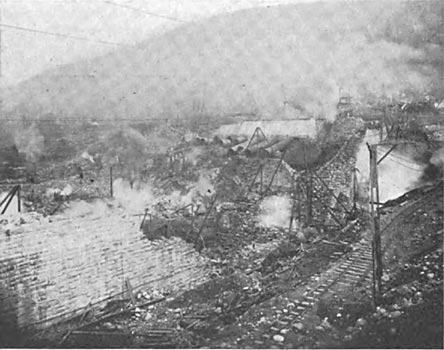
Water passes from the canal to the power house through ten steel tubes of 12 ft. inside diameter each. Before entering the power house these tubes pass through a heavy masonry retaining wall that protects it from water on the side toward the canal. Each of these ten tubes connects with a wheel case that contains a pair of turbine wheels mounted on a horizontal shaft. In each of eight of these cases the pair of turbines is rated at 5,000 hp under a head of 80 ft., and in each of the other two cases the pair of wheels is rated at 3,400 hp. Each of the eight pairs of larger wheels will drive a direct-connected electric generator rated at 2,500 kw, and each of the two pairs of smaller wheels will drive a 2,000-kw generator. All of these generators are of the revolving magnet type, three-phase, 40-cycle, and made by the General Electric Company. Each pair of wheels is controlled in speed by a Lombard governor belted to its shaft. To each of the two cases containing the 3,400-hp wheels there is connected a small wheel case whose turbines drive an exciter for the main generators.
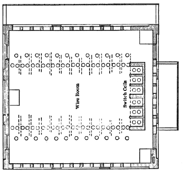 |
| Fig. 5. Second Floor Plan of Switch House. |
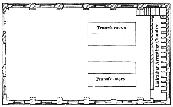 |
| Fig. 6. Floor Plan of Sub-Station. |
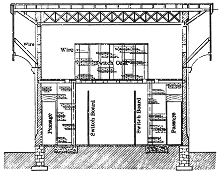 |
| Fig. 7. Cross-Section of Switch House. |
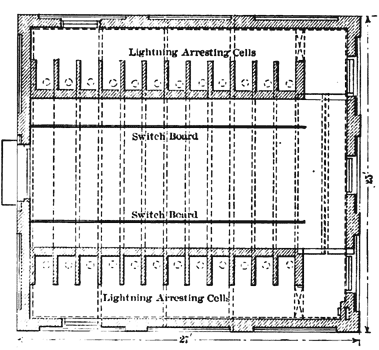 |
| Fig. 8. Ground Floor Plan of Switch House. |
From the foregoing it may be noted that the total capacity of main water wheels at this station is 46,800 hp, and the total capacity of main generators 24,000 kw, or 32,000 hp. The three-phase, 40-cycle currents from the main generators will be raised in pressure to 26,500 volts by transformers at the main station and thence transmitted to sub-stations located at Glens Falls, Fort Edward, Saratoga, Ballston, Schenectady and Watervliet, and numbering six in all at the present time. Energy from these sub-stations will be supplied for lighting, general power purposes and electric traction. In some cases, as at Saratoga and Ballston, where the local electrical supply systems are owned in common with the transmission system, energy will be distributed from the sub-stations directly to consumers. In other cities and towns, as in Albany, Troy and Schenectady, energy from the sub-stations will be sold to local lighting or traction systems. At Schenectady the sub-station is divided into two distinct parts, one of which will contain apparatus belonging to the General Electric Company, whose works are to utilize a large amount of the transmitted energy, and the other part will be devoted to service in the city. From the sub-station at Watervliet energy will be distributed for lighting, power and traction there, in Troy and in Albany, also for power and lighting in Lansingburg.
| |||
| Fig. 9. the Valley to Be Flooded. |
At the Glens Falls sub-station the equipment includes four transformers of 500 kw and 40 cycles each, which take current from the line at 26,500 volts and deliver it at 2,300, 2,400 or 2,500 volts as desired. At this sub-station there are two blower sets and one automatic F.R.T. of 45 kw and 150-volts capacity, besides the switchboard equipment. One three-phase feeder enters this sub-station at a pressure of 26,500 volts, and it has 6 outgoing lines for distribution at 2,300 volts each. Among the service supplied in Glens Falls is that of 2,000 hp to motors in a portland cement works. In the Saratoga sub-station the equipment is the same in capacity as that at Glens Falls except that the F. R. T. is lacking.
The plant at Glens Falls and the transmission system just described are the property of the Hudson River Water Power Company, which also owns another undeveloped water power on the same river. This company also own and operate a large water power plant at Mechanicsville on the Hudson, which was described in the ELECTRICAL WORLD of September 3, 1898. As soon as the plant at Spier Falls is completed, the two plants will be connected with the same transmission system. Work on the dam at Spier Falls was begun in June, 1900, and it is expected that the generating station will be ready to deliver 15,000 hp in July of the present year.
In the water power development William Barclay Parsons and George E. Evans have acted as consulting engineers. Charles E. Parsons is chief engineer in charge of the work. To Eugene F. Ashley, president of the Hudson River Water Power Company, the conception and execution of this great generating and transmission system is primarily due. Chief Engineer Parsons and other officials of the company have extended every courtesy for the collection of the above facts.
When the Hudson at Spier Falls and other adjacent points shall have been made to yield up its energy for useful work, electrical supply in the cities named will be largely independent of coal.
