[Trade Journal]
Publication: Electrical World and Engineer
New York, NY, United States
vol. 42, no. 19, p. 749-752, col. 1-2
Transmission of Hudson River Power.IlII.
(Concluded.)
WITHOUT following out in detail the arrangement of switches and lines at the Saratoga and the Alplaus switch houses, it may be said in general that in each place either transmission line from a generating station may be connected to either line running to a sub-station.
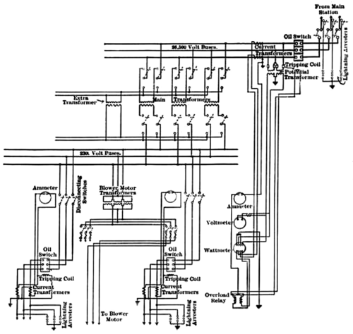
The flexibility of the connections between the generating and sub-stations is further illustrated by the sub-station at Watervliet, where lines operating at 26,500 volts from Spier Falls and lines with a pressure of 10,800 volts from Mechanicsville converge. All oi the other sub-stations for railway and lighting work in the vicinity of Albany and Troy are fed through the Watervliet sub-station at about 10,800 volts pressure. In addition to provision for a local service at 2,300 volts, the Watervliet sub-station must, therefore, provide for supply to either of these connected sub-stations from either of the lines from the Spier Falls and Mechanicville generating plants. To accomplish this result a single pair of bus-bars is pro- vided at Watervliet, and each bus-bar of the pair is divided by knife switches into as many sections as there are individual wires in the several transmission lines that enter this sub-station from the water power plants. Each wire of the 10,800-volt circuits from Mechanicville, after passing through an oil switch, may be connected to a section of either one of the two bus-bars by means of a double-blade knife switch. Each wire of the 26,500-volt circuits from Spier Falls. after passing through an oil switch, may be connected by a knife switch with the primary winding of a transformer designed to reduce the pressure from 26,500 to 10,800 volts. The secondary coil of each of these transformers may be connected to a section of either one of the two bus-bars by a double-blade knife switch. A similar switch connects each section of either bus-bar with an oil switch that is in turn connected to one of the wires of a 10,800-volt circuit that runs to one of the other sub-stations at Albany or Troy. Another set of knife switches can be used to connect any wire from Spier Falls with either of two transformers that normally have their primary coils connected to other wires. Besides the switches already mentioned for cutting the two 10,800-volt bus- bars into sections, these bars are further cut into two groups of sections by a double-pole oil switch with a knife switch on each side of each pole. To one of these two groups come all the wires from Spier Falls, and to the other group come all the wires from the Mechanicville plant. By means of these two sectionalized bus-bars and the various switches mentioned, any single wire from either of the two water power plants may be connected to any wire running from the Watervliet sub-station to either of the sub-stations which it supplies, either directly or through one of the step-down transformers.
| |||
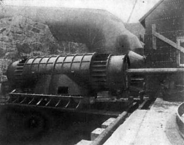
| Fig. 13.One of the Water Wheels. |
At the Albany sub-station, whence the motor generators and transformers of the Albany Electric Illuminating Company are fed, the arrangement of knife switches, oil switches and bus-bars permits either of the three 10,800-volt, three-phase circuits from the Watervliet sub-station to supply either of three 10,800-volt circuits for synchronous motors, through either of two automatic voltage regulators. Furthermore, either of the 10,800-volt incoming power circuits may be connected to the primary coils of transformers that reduce the pressure to 2,300 volts for distribution feeders.
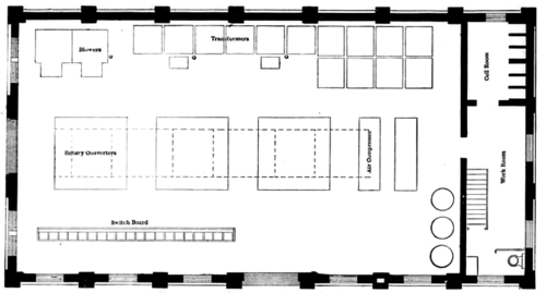 |
| Fig. 14.First Floor Plan Saratoga Sub-Station. |
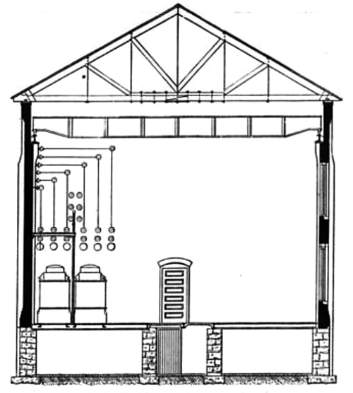 |
| Fig, I5.Cross-Section of Saratoga Sub-Station. |
The details of connections between the 26,500-volt transmission circuits and the 2,300-volt distribution circuits at the several sub- stations are illustrated by those at Glens Falls. At that sub-station the three wires of a transmission circuit, after entering double-blade knife switches that connect them at once with lightning arresters and oil switches, terminate in the three 26,500-volt bus-bars. To these bus-bars are connected the current and potential transformers that supply the ammeter, voltmeter and recording wattmeter with its overload relay and tripping coil.
The primary coils of each of three transformers may be connected with these 26,500-volt bus-bars through single-pole, double- throw knife switches. The secondary coils of these same transformers may be connected through similar switches to the 2,300-volt bus-bars that supply the distribution circuits. A fourth transformer has its primary coil connected to one terminal of each of the six double-throw switches that are normally used to join the 26,500-volt bus-bars with the primary coils of the three transformers just named. In a similar way the secondary coil of this fourth transformer is permanently connected to one terminal of each of the six double-throw switches normally used to join the secondary coils of the three transformers with the 2,300-volt bus-bars. These several connections make it possible by throwing four of the single-pole switches to completely disconnect either of the three transformers first named from the 26,500-volt and the 2,300-volt bus-bars, and to connect the fourth transformer in the place of the one thus disconnected.
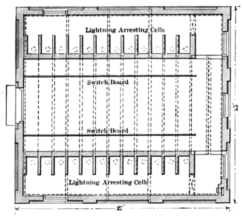 |
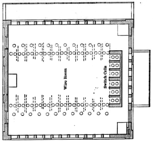
| Fig. 16.Ground Floor Plan of Switch House. |
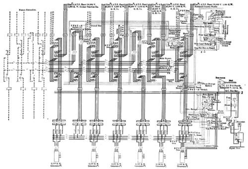 |
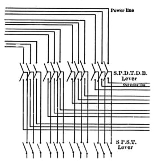
| Fig. 17.Switchboard Connections Spier Falls. |
 |
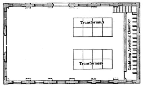
| Fig. 18.Second Floor Plan of Switch House. |
The switch houses at Saratoga, Alplaus and Schenectady correspond in general features of construction, though differing as to size and the number of connected circuits. In each case the walls of the switch houses are brick, the main floor concrete without a basement underneath, and the second floor is made up of concrete and expanded metal resting on steel I beams. Above the second story of each house comes the slate roof supported by planks secured to timber trusses.
 |
| Fig. 19.Floor Plan of Sub-Station. |
 |
| Fig. 20.Switchboard Wiring Glens Falls Sub-Station. |
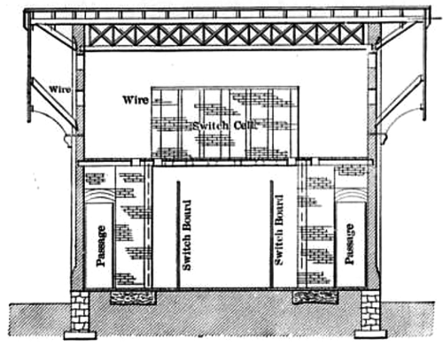 |
| Fig. 21.Cross-Section of Switch House. |
 |
| Fig. 22.Sub-Station Transfer Switches. |
The sub-stations built by the company at Glens Falls, Fort Ed- ward, Saratoga, Ballston Spa and Watervliet, though differing in details, follow the same general type of construction, of which the Saratoga sub-station may be taken as an example. This last-named sub-station has an outside ground area of 72 ft. 10 in. x 39 ft. 2 in., and is two stories high, with a distance of 30 ft. from the ground line to the eaves of the slanting roof, and 42 ft. to the ridge. The walls of the sub- station are brick and the roof is slate laid on 2-in. matched spruce planks supported by timber trusses. Underneath the entire building is a basement with a cement floor 6.5 ft. below the first or main floor. From first floor to the lower chords of the roof trusses measures 28 ft. Stone foundation walls of the sub-station are 2 ft. thick, and extend all around the outside to a distance of 18 in. above the ground level. There are also three interior foundation walls each 20 in. thick. Starting from the top of the foundation the outside brick walls of the station shrink to a thickness of 1 ft. after a rise of a few inches. On the longer sides of the station and spaced at intervals of 8 ft. are piers in the brick wall that increase its thickness to 25 in. At a distance of 22 ft. 7 in. above the main floor seven of the piers on each of the two longer walls are reduced in thickness so as to form ledges on which rests an I beam for the traveling crane. By means of the interior foundation walls and double doors connecting them a large part of the basement is formed into a compressed air chamber. Into this chamber air is forced by motor-driven blowers on the first floor, and over openings in the floor the air-blast transformers are set. This first floor is of concrete with expanded metal supported in part on 6-in. and in part on 9-in. I beams, according to the weight to be carried. An 8-in. brick partition divides the first floor of the sub-station into a greater and a lesser part, the former being 35 ft. x 61 ft. 1 in. An- other 8-in. brick partition cuts the lesser portion of the first floor into two parts, one of which is used as a work room, and the other, measuring 8 x 11 ft., forms the cell room for the knife and oil switches and lightning arresters on the 26,500-volt lines. This cell room extends up through two stories, has a second floor and the high-voltage lines enter its upper part. Along that side of the main floor of the sub-station which is next to the cell room a row of transformers is placed, and the 26,500-volt lines, after leaving the cell room, pass to these transformers over porcelain insulators mounted on the surface of the wall above them. To give ready access to the knife switches that connect these lines with the primary coils of the transformers a gallery 48 ft. 6 in. long and 5 ft. 5 in. wide is erected on the side wall where they are located, and at a distance of 11 ft. 4 in. above the first floor. On the opposite side of the main room of the sub-station from that where the transformers are located is the switchboard with its back 4 ft. 7 in. from the wall. In the center of this main room are spaces for three rotary converters and two air compressors. The two motor-driven blowers occupy a position in line with the row of transformers.
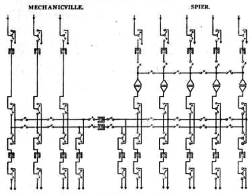 |
| Fig. 23.Main Connections Watervliet Sub-Station. |
The Glens Falls sub-station is devoted to the operation of lamps and stationary motors in that city, where the Hudson River Water Power Company own the local electrical supply system. Of the four 500-kw transformers at this sub-station, three are regularly used to receive the 26,500-volt, 40-cycle, three-phase current and to de- liver it to the 2,300-volt bus-bars. The fourth transformer of like capacity with the others is a spare. The 2,300-volt current is distributed for arc and incandescent lighting and induction motors. Enclosed 500-watt arc lamps for interior use have been operated during some months with the 4o-cycle alternating current, and have given good results. At the works of the Glens Falls Portland Cement Company induction motors with a total capacity of 1,000 hp are to be supplied from this sub-station. The load of smaller motors scattered about the city amounts to about 300 hp.
At Saratoga, where the local electrical supply system is also in the hands of the water power company, the sub-station contains four of the 500-kw transformers like those at Glens Falls. Here again 2,300-volt, 40-cycle, three-phase current is supplied for are and incandescent lighting and induction motors. The series arc street lamps at Saratoga will be operated with constant-current transformers. Included in the load of 350 hp of induction motors operated from the sub-station at Saratoga are three of 20 hp each on vertical shafts in the new sewerage pumping station of that city. Each of these motors is rated to pump 1,150 gallons of sewerage per minute, and all three are controlled by automatic regulators, so that they start and stop according to the requirements of the sewer system.
In Ballston Spa, where the local electrical supply system is also in the hands of the water power company, the sub-station, when completed, will contain three transformers like those at Glens Falls and Saratoga. This Ballston sub-station will be occupied in part by the transformers and converters of the Schenectady Street Railway, which uses some of the power sold to the General Electric Company.
Much the largest sub-station of the water power company is that at Watervliet, which will contain nine transformers of 1,000-kw capacity each. Here the 26,500-volt current from Spier Falls will be reduced in pressure to 10,800 volts and then transmitted, along with the 10,800-volt current from the Mechanicsville plant, to sub- stations of the local electrical supply systems in Lansingburg, Troy and Albany, also to sub-stations of the United Traction Company. The Watervliet sub-station is partly erected, some of its apparatus is already in regular operation, and it is supplying power to the sub-stations of the traction company. By the first of the coming year it is expected that the local electrical supply systems in Troy and Albany will be drawing energy from the same source.
All of the electrical apparatus at the stations and sub-stations of the above transmission system was built by the General Electric Company.
Description of this notable application of water power to electrical supply has been obtained through the kind co-operation of Mr. C. E. Parsons, chief engineer of the work at Spier Falls, and of Mr. J. D. Hilliard, Jr., manager of the electrical construction department of the system.
