[Trade Journal]
Publication: Electrical World and Engineer
New York, NY, United States
vol. 44, no. 6, p. 201-206, col. 1-2
The Guanajuato, Mexico, Power TransmissionI.
BY ROBERT McF. DOBLE.
THE WATER POWER.
THERE has recently been completed in the States of Michoacan and Guanajuato, Republic of Mexico, at the location shown on the accompanying sketch map, a notable hydro?electric power development and high-potential, long-distance transmission. Under a concession from the Department of Encouragement, Colonization a n d Industry of the Republic of Mexico, the Guanajuato Power & Electric Company constructed a canal, pipeline, power generating station, transmission 1ine, sub-stations and distributing systems for developing and marketing the motive power of 8,000 liters (283 cu. ft.) of water per second of the Duero River.
| |||
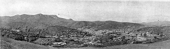
| Fig. 1. - City of Guanajuato, Mexico, to Which Power is Transmitted 100 Miles at 60,000 Volts, for Mining. |
The Guanajuato plant is a very interesting one because of its many advanced engineering features, the remarkably short time within which it was constructed and the fact that the work was completed within the estimates of cost. Some of its distinctive features are the following: Massive and permanent construction of head-works, canal and power house; methods of regulating and measuring the water and of collecting and disposing of the detritus carried by the water during the rainy season; large pipe line with low velocity, with no horizontal angles and but few vertical angles of long radius, riveted together, forming one continuous pipe with both ends-bedded in masonry, laid in a deep trench and completely covered no receiver, the pipe terminating in branches leading directly to the water wheel nozzles, which have 7-in. jets, the largest yet used; two-bearing type of hydro-electric unit, with two 1,125-hp water wheels mounted directly on the ends of the generating shaft and overhanging the bearings; 60-kilovolt, 101-mile transmission, specially designed porcelain insulators, larger than any heretofore used, and 19-strand, hard-drawn copper cable; long-span steel tower line construction, not more than 12 towers being used to the mile.
| |||
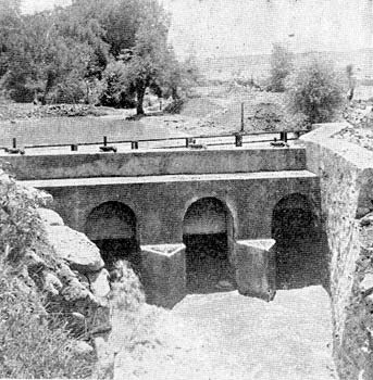
| Fig. 2. - Head Gates From Down Stream Side. |
The inception and development of this enterprise are interesting. Some three or four years ago Mr. Leonard E. Curtis, who had been for a long time counsel in patent matters for the Westinghouse Electric & Manufacturing Company, and who had been obliged to leave New York and go to Colorado on account of his health, was sent to Guanajuato by clients to examine the title to certain mining properties there. In the course of this examination he became interested in the place and was impressed with the very high cost of the power used for mining operations. Being familiar with modern developments in long-distance electrical transmission, it occurred to him that the conditions there were exceedingly favorable for the introduction of electric power if a suitable water power could be found within working distance. He employed a young American, whom he found there, to search for a water power, giving him a radius of 100 miles from Guanajuato to work in. The water power which has since been developed was found and an option obtained on it during the following year. In the meantime Mr. Henry Hine, under whose management the Stanley Electric Manufacturing Company had been built up, and who had resigned his position in that company when the ownership of it changed hands, had joined Mr. Curtis in Colorado, and the two had taken up the installation of power transmission giants together. After making a preliminary examination, they presented the matter to prominent capitalists in New York and Boston, who subscribed quickly the necessary capital, subject to an engineering examination. This examination was made by Mr. Robert McF. Doble, of San Francisco; Mr. H. H. Filley, of Kansas City, and Mr. Charles T. Main, of Boston. Their report was favorable, and the company was organized and proceeded with the construction work. Mr. Filley was employed as chief engineer of the company, Mr. Doble as consulting engineer, and Mr. Norman Rowe, formerly with the Westinghouse Company, was put in charge of the construction work at Guanajuato, where he now has charge of the plant as general superintendent.
 |
| Fig. 3. - Map of Guanajuato Power Transmission. |
 |
| Fig. 4. - Map Showing Location of Head Works, Canal and Pipe Line. |
The designs and specifications were prepared in San Francisco. The iron work for the canal and the massive steel pipeline were Ordered from Messrs. Joseph T. Ryerson & Son, of Chicago. The plates for the pipeline were made in Germany, transported by sea to New Orleans, up the Mississippi River and by rail to Cudahy, Wis., and shaped and riveted in the new and finely equipped shops of the Holthoff Machinery Company there. The water wheels were constructed by the Pelton Water Wheel Company in Philadelphia. The electric generators and transformers were built at the factories of the General Electric Company, at Schenectady, The transmission cables were shipped from the shops of the Ansonia Brass & Copper Company, at Ansonia, Conn. The steel towers supporting the cables were manufactured by the Aermotor Company, at Chicago. The insulators were made by the Locke Insulator Manufacturing Company, at Victor, N. Y. The poles for the distributing circuits were bought in Texas, and the Portland cement for the masonry was brought in from Germany. From these various sources the materials came by sea and by land to the railway station at the quaint Mexican city of Zamora, whence they were hauled on wagons.
| |||
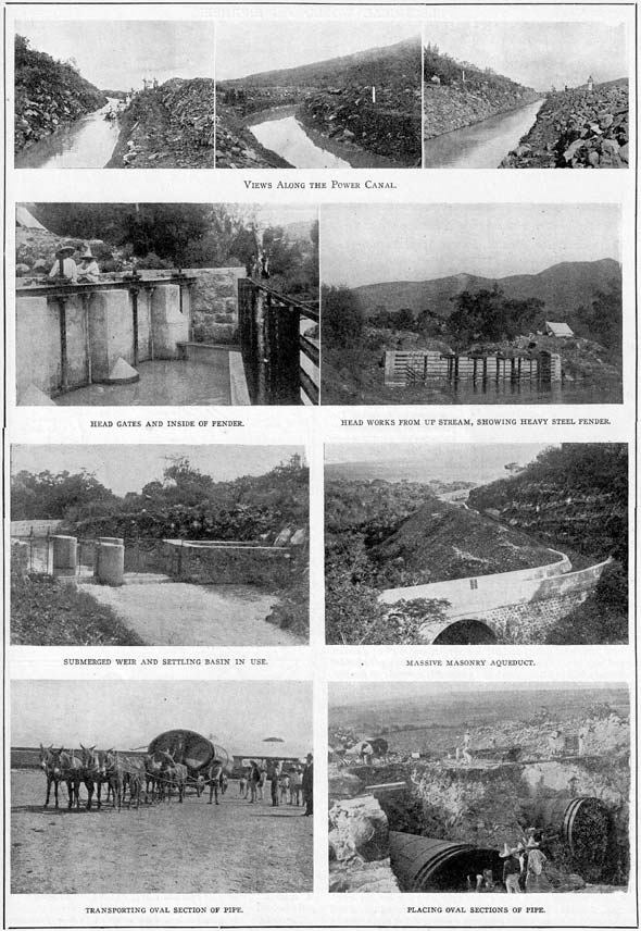
| Fig. 5 to 13. - Hydraulic Work on the Guanajuato Transmission. |
The water supply is taken from the Duero River, where it is formed by the confluence of the Camecuaro and Chilchota Rivers. Little is known of the watershed supplying the Duero River except that it is large and high. This portion of the State of Michoacan is a series of fertile valleys lying one above the other, very like a series of vast terraces. About ten miles to the south of the Zamora Valley and about 400 ft. higher in elevation lies the broad, beautiful and fertile valley of Tangancicuaro, beyond which, to the south, at a greater elevation, lies the valley of Los Once Pueblos (The Eleven Villages). The Tangancicuaro Valley is nearly surrounded by mountains, which toward the south are timbered and reach an altitude of from 10,000 to 12,000 ft. Lake Patzcuaro, a large and deep lake with no known outlet is located high up in this mountain range.
The entire area is of volcanic origin. The rain waters falling upon the high mountain lands penetrate the crevices in the basalt, percolate slowly to lower impervious strata, and then issue from the springs which abound in the valleys mentioned. The catchment area is so extensive and the distances which the water probably traverses so great that the subterranean reservoirs yield an exceedingly uniform volume from the numerous springs, which, during the dry season, furnish the entire volume of the Duero River. Such geological formation and source of supply for a river of considerable and uniform discharge is not without a parallel, though somewhat uncommon. Similar cases may be found in the lava districts of Northern California.
The Duero River is formed by the confluence of the Camecuaro and Chilchota Rivers, which unite at the northerly edge of the Tangancicuaro Valley, just above where a low ridge of basalt crosses between the neighboring mountains. Through a break in this formation the river commences its rapid descent into the Zamora Valley, almost 400 ft. below. The Chilchota branch, with its many tributaries, extends in several directions throughout the Tanganciacuaro Valley and to the similar valleys terraced above it, notably Los Once Pueblos, where are located the Chilchota Springs. It has a very extensive watershed reaching to the high timbered mountains, and from it extensive irrigation is practiced. Hence, during the rainy season it becomes a rushing torrent and during the dry season the demands upon it greatly diminish its volume. Its banks are closely lined with the sabino (or ahuehuete) trees, and from an eminence its course can be plainly traced through broad wheat fields.
The Camecuaro branch is only about a mile in length, with practically no catchment area. It is supplied by a large group of springs, the water issuing from the lava formation on tile northerly side of a low hill. These picturesque springs are surrounded by a fine grove of very large sabino trees, which also closely line the banks and confine the stream within its meandering channel until it unites with the Chilchota. The Camecuaro branch has very little fall from its source to the Chilchota, and it is plainly evident that its volume is remarkably uniform throughout the year. No water is taken from it for irrigation, but at times it receives a small addition to its volume as a result of the excessive irrigation of the wheat fields lying above it with water brought through a ditch from another spring.
A number of careful current meter measurements were made and compared with figures collected from every possible source, to determine the minimum discharge of the Duero River. This resulted in the conclusion that there would never be less than a sufficient quantity of water available to warrant the construction of a generating plant of 8,000 electrical hp capacity. The possibility of increasing the low water flow by means of storage reservoirs located in the high mountains has not yet been fully investigated. There are, no doubt, many places in the large catchment area suitable for reservoirs.
Between the point where the water may be taken from the Duero River, namely, at the confluence of the Camecuaro and Chilchota branches, to the point where it must be returned to the river, namely, at the Chaparacho Dam, there are three dams in the river for the purpose of diverting portions of its waters into irrigation canals for the ranches of La Rojena, La Planta and Tamandaro.
The accompanying plot of the river, canal, pipeline, etc. (Fig. 4), shows clearly the general plan of development. The native dams in the vicinity are in strange contrast with the type of construction now to be described. The masonry diverting dam is built of volcanic rock, the interior being laid up with lime mortar and the exterior with Portland cement. It is a curved structure with a radius of 88.19 meters, the length of the crest being So meters. Its elevation is 1,662.40 meters above sea level. It is computed as a gravity dam for a maximum depth of 1.60 meters of water over the crest. A heavy steel fender securely braced against the masonry protects the entrance to the canal from the drift brought down by the freshets during the rainy season. Water is admitted to the canal through four head gates, each with an opening 1.25 by 2.00 meters, at a maximum velocity of about 0.80 meter per second. These head gates, run in an angle-iron frame set in the concrete, are made of wood heavily ironed, and are operated by means of a screw stem and worm gear nut, with ball bearings, which is turned by means of a hand crank operating a worm spindle with bronze thrust collars.
The canal is 6,650 meters long, is of trapezoidal section 4 meters wide on the bottom and 2.10 meters deep. The side slopes are 1:1 in soft earth, 0.5:1 in hard rock and 0.2:1 where the canal is lined with cement. Its slope is uniform 1:2,500. Its carrying capacity is 283 cu. ft. per second at a velocity of between 2 and 3 ft. per second.
To provide for accurately measuring the volume of water allowed under the concession, a "rating flume" was constructed near the head works. It is about coo ft. of straight canal, lined with Portland cement, held in place by sheets of expanded metal. The top of the wall on the side toward the river is finished with an adjustable metal weir, which is set so as to act as a spillway when more than the proper volume of water is flowing. A short distance down stream the canal is widened and deepened, causing a reduction in the velocity of the flowing water to about one-third of the normal, so that any sand may settle to the bottom. This settling basin is provided with six valves opening from its bottom into a culvert which leads out from under the canal to the river. These valves are of new and interesting design, consisting of a circular cast-iron opening 18 in. in diameter closed by means of a conical cast-iron bell drawn point up into the opening from below and held there by means of a threaded stem and nut, which rests upon two channel beams spanning the canal. By turning the nut the cast-iron bell may be lowered to open the valve and wash out the sand which has collected at the bottom.
Immediately below the settling basin there is an adjustable submerged weir. By means of the head gates and by the adjustable lip at the rating flume, in conjunction with the submerged weir, the quantity of water flowing in the canal may be closely regulated. At the time the photographs were taken there was very little water flowing in the canal, as it was being filled for the first time to test and to furnish water for puddling the canal.
From this point the greater portion of the canal is of the character shown in the photographs. It meanders along the southerly side of the canyon under a substantial masonry arch road bridge 33 ft. wide and 16 ft. span, over a massive masonry aqueduct to a spillway (photograph No. 20), and thence to a second sand trap near the fore-bay. The spillway and second sand trap are located so as to make use of the Barranca de La Rojena as a waste water way leading to the Duero River.
A small storage reservoir is constructed alongside the canal at the forebay, by means of which a sufficient reserve of water is maintained to admit of cleaning the canal when required, and also to carry a very considerable peak load in excess of the normal capacity of the canal. A simple arrangement is provided for allowing the surplus water to flow into the reservoir from the canal during the hours of light load, and at the same time maintain the maximum head or pressure on the pipeline, regardless of the elevation of the water in the reservoir.
Four suitable check valve automatic gates are placed in the reservoir near its bottom, opening outward into the forebay. as the supply of water in the canal is equal to or in excess of the discharge through the water wheel nozzle in the power house at maximum water level is maintained in the forebay; if there is surplus of water it overflows from the forebay into the reservoir over a suitable weir. Whenever the requirements of the water A are in excess of the quantity of water flowing in the canal the water level in the forebay is lowered, relieving the pressure on the outlet of the check valve gates, and allowing the water in the reservoir to be discharged to automatically make up the deficiency. At the entrance to the forebay the water passes over a measuring weir. On passing from the forebay to the penstock the water flows through the screen which removes all floating debris.
The massive masonry penstock shown is strengthened by iron hoops imbedded in its walls, and is interesting because of its excellent hydraulic lines. The water, after passing through the screens and through four gates similar to those at the head works, enters two ellipsoidal masonry basins which gradually diminish in diameter toward the bottom, merging into the great oval taper sections which are the heads of the pipelines. This design causes a gradual acceleration in the velocity of the water and also prevents the formation of the whirling vortex which would draw air into the pressure pipe.
The pipeline is 2,300 ft. long, with no lateral bends. It varies in diameter and thickness, as shown in the following table, and was designed with a safety factor of five:
The decrease in the diameters of the pipe section causes an acceleration in the flow of the water as it descends. This also makes possible the testing of sections for shipment. The pipe was made up from steel plates in sections 27 1/2 ft. long and weighing from 7,000 to 10,000 pounds each. The plates were carefully selected and tested, being required to have the following characteristics: Tensile strength, 52,000 to 62,000 pounds per sq. in.; elastic limit, not less than one-half the tensile strength; elongation, 25 per cent.; 180° cold quench bend flat on itself without fracture on the outside of the bent portion. There are 480 separate plates in the pipe, each rolled tapering, the small end of one fitting inside the large end of the one next below it.
All seams were lapped, and the longitudinal seams were designed so as to have at least 70 per cent. of the strength of the plate. These longitudinal seams were placed so that they are on top of the pipe and alternately opposite, with the caulking edges up. The longitudinal seams are double riveted; the circular seams single riveted. All the shop riveting was done by a large hydraulic riveter. The field riveting was done by hand by a gang of expert boilermakers sent to Mexico for that purpose. Two riveters, a helper and a man at the forge to heat rivets could finish one circular seam in a day. When riveted the pipe was caulked and an extra coat of preservative paint was applied. Each section of the pipe had on top near its lower end a hole through which the hot rivets were passed from the forge to the man inside. The hole was tapped and a plug screwed in after the joint was riveted. Each section was plainly marked at the factory with letters indicating its position in the pipeline.
The common practice of laying pipes of this character on top of the ground and supporting them on piers was not followed. A deep trench was dug, the bottom of which was graded on long tangents and with slight vertical angles. The pipe was laid in this trench, beginning with the section nearest the power house and riveting on section after section, working up hill. Bell holes were dug in the bottom of the trench so that the riveters might have room to swing their hammers. The back filling of the trench was done with great care, the earth being dampened and thoroughly tamped under and around the pipe. During the early morning hours, while the pipe was cool and at its minimum length, the top covering was completed.
On August 24, 1903, the pipe was tested and so well had the work been done that not a single leak was found, although there are over 70,000 rivets. The pressure pipe terminates at the bottom of the hill in branching cast-iron pipes leading through the south wall of the power house to the nozzles. The power house, which will be treated in Section II, has masonry walls built of native volcanic rock. The roof is of galvanized iron, supported by steel roof trusses and lined with an anti-condensation lining. As shown by the photographs, it is built in an excavation extending to a considerable depth below the natural surface of the ground. This was done for economical reasons; the pipeline profile being quite flat at the lower end, where the pipe is the thickest and most expensive, it was concluded that it would be cheaper to excavate a longer length of tailrace and to dig deeper for the power house than to extend the pipeline, as each additional foot on the 47-in. pipes 5/8 in. thick would cost a considerable amount.
