[Trade Journal]
Publication: Electrical World and Engineer
New York, NY, United States
vol. 44, no. 8, p. 285-288, col. 1-2
The Guanajuato, Mexico, Power Transmission. - III.
BY ROBERT McF. DOBLE.
TRANSMISSION LINE.
THE 100-mile, 60,000-volt transmission line differs materially in design from any line heretofore constructed, notably in the use of a hard-drawn copper cable instead of the usual solid conductor, metal pins, cross arms and towers for supporting the insulators, and unusually long spans. From the power-generating station near Zamora the line passes for about 30 miles over rough mountainous lava formation cut by deep ravines. Near Guanajuato there also is some rough country, but for about 60 miles the line passes over clear, rolling country, the most of which is under cultivation.
| |||
| Fig. 33. - Working on the Line. |
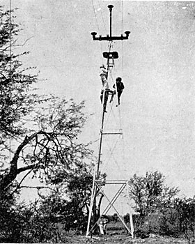
The conductors are 19-strand, hard-drawn copper cables approximately 3/8 of an inch in diameter, equivalent in carrying capacity to a No. I B. & S. G. wire and weighing 1,340 pounds per mile. This type of conductor was finally determined upon, after much study and many tests, because of its high conductivity, flexibility and mechanical strength; the wires composing it having a tensile strength of over 55,000 pounds per sq. in. The cable was made and shipped in lengths of about two miles. The joints were made with special copper tube connectors 12 in. long and elliptical in cross section. The two ends to, be joined were passed through the connector in opposite directions and three complete twists were given by means of special wrenches. The engravings show the making of a joint. No soldering was done. The cables are placed in grooves on top of the insulators, 78 in. apart, at the points of an equilateral triangle, and are tied in with No. 14 soft-copper wire, it being considered that the small wire wrapped about several times would make an easy tie and not be apt to damage the small, hard-drawn strands of the cable. In stringing, the cables were pulled over the cross arms on rollers. The cable was shipped on reels in lengths of about two miles.
Where the topography and roads, permitted, six of the reels were delivered from the wagons each four miles. The cables then were pulled out, spliced and tied in. In the mountainous sections the cable had to be cut into shorter lengths. Diagrams showing the proper sag to be allowed at various temperatures and for spans up to 1,320 ft., were prepared, based on a maximum strain of 20,000 pounds per sq. in., in the coldest weather and with the most severe wind. The calculations include an allowance for the mechanical elasticity of the cable.
| |||
| Fig. 34. - Cementing Together Insulator Parts. |
The Locke insulators are larger, heavier and better than any heretofore used, and were required to stand a test potential of 120,000 volts for five minutes. They are over 12 in. in height and 14 in. in diameter and weigh about 15 pounds. They are made of porcelain with a brown glaze and consist of four parts. The top and the first petticoat were glazed together in the kiln and the other two joints were made with neat Portland cement. The pins were likewise secured into the completed insulator, as shown by cross-section drawing of the pin and insulator.
| |||
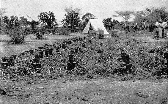
| Fig. 35. - Distributing Insulators Along the Line. |
The pins are of cast iron, conical in shape and cored hollow. The pin which carries the top insulator has an enlarged base, threaded on the inside, and is screwed on to the end of the 3-1/2-in. extra heavy pipe, which projects from the top of the tower. The pins which carry the lower insulators have rectangular bases, which are securely clamped between the ends of the 4-in. channels, which constitute the cross arm, as shown in the sketch of the top of the tower.
| |||
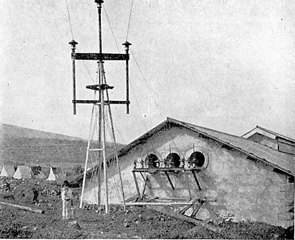
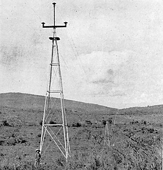
| Fig. 36.-- the First Tower of the Transmission Line. |
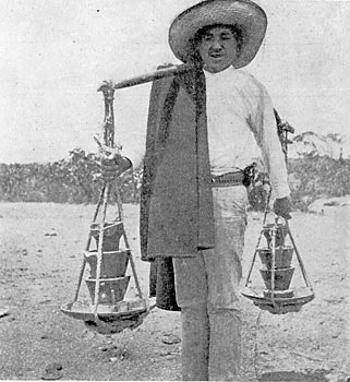
The insulators were shipped in two parts, in barrels, and the cementing together of the parts and the cementing in of the pins had to be done in the field. After the parts were assembled the "field" was covered with the packing straw from the barrels in order to protect the insulators from the hot sun while the cement was hardening. The completed insulators with the pins in place were then carried out from the construction camps to the required location on the line, two at a time, by "man power" as shown. This was found to be the most satisfactory and economical method, as human labor is very cheap in Mexico.
| |||
| Fig. 37. - Making A Splice in the Cable. |
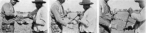
Note: under left photo: READY TO TWIST; under center photo: TWISTING; under right photo: SPLICE COMPLETED; then add the Caption
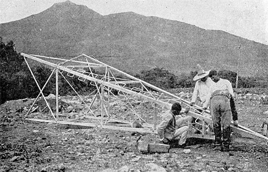
The towers are special 40-ft., four-post galvanized steel structures, weighing about 1,500 pounds, made of 3-in. x 3-in. x 3/16-in. angles, braced and stayed with smaller angles and rods. Each post terminates in an anchor consisting of a piece of angle iron 30 in. long secured at right angles. The construction is clearly shown in the photographs. A 40-ft. tower with the 3-1/2-in. extra heavy pipe fixed in position at the apex was built for testing at the factory of the Aermotor Company. This tower was bolted in its assembled, state to the 30-in. wall of a five-story brick building, so that its axis was horizontal instead of vertical, as normally; a rope sling was attached to the pipe 70 in. above the apex of the tower and to this a wooden platform was attached. Weighed masses of pig iron were then placed upon this platform and the deflections of pipe and tower noted. When the load amounted to 900 pounds the pipe began to show signs of yielding; the tower, however, was perfectly rigid. When the load was 1,234 pounds the deflection of the pipe from a straight line amounted to about 6 in. On removing the load a permanent deflection of about 1 in. was found. The load was replaced and increased about 70 pounds at a time. With each increase the pipe took an additional permanent set, and at a load of 1,560 pounds it continued to bend until the load rested on the floor.
 |
| Fig. 38. - Cross-Section of 60,000-Volt Insulator and Metal Pin. |
The all-metal construction of the supports for the transmission line was determined upon only after very thorough study and analysis and with a full realization of the fact that the insulators must then be of the most reliable and ample construction. The quality and suitability of the insulators were, therefore, carefully looked after.
The advantages of long spans, with consequent reduction in number of supports and of insulators required were so obvious that it was at once decided to adopt that type of construction. After careful study and many calculations and estimates the 40-ft. towers spaced twelve to the mile were determined upon. The towers are spaced 440 ft. apart, twelve per mile, except near Guanajuato, where the nature of the ground necessitated the use of a few 60-ft. towers and spans up to 1,320 ft. in length.
The No. 9 B. B. double galvanized-iron wires for a telephone circuit are fastened on the transmission towers 10 ft. below the copper power cables. They are tied to regular glass insulators placed on 12-in. painted oak brackets bolted to tower legs. The telephone wires are transposed one complete revolution every four towers; the power cables are not transposed. High-resistance instruments are used, and the telephone service is quite satisfactory. The climatic conditions for high-voltage transmission are usually good and during the dry season when the water is lowest, and when all the losses should be kept at a minimum, the atmospheric conditions are very favorable.
 |
| Fig. 39. - Elevation of Cross-Arm and Pipe. |
The long line of shining galvanized steel towers catches the eye of the traveler as the train nears Palo Verde on the Guadalajara branch of the Mexican Central Railroad, or on approaching Irapuato on the main line from the north, at which points the transmission line crosses the railroad. It is almost straight, there being only a few slight horizontal angles. The line is divided into four sections of about 25 miles and is in charge of a superintendent whose headquarters are at the middle storehouse. At each of the three division points there is a first-class storehouse, a set of 60,000-volt disconnecting switches in the main line, a line foreman and patrolman, both mounted. In the middle of each section there is a second-class storehouse in the care of a mounted patrolman.
| |||
| Fig. 40. - Transmission Towers Erected and Cables Strung. |
THE SUB-STATIONS.
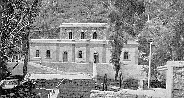
At Guanajuato the transmission line cables enter the sub-station through a set of 60,000-volt disconnecting switches, the same as at the generating station. The Guanajuato sub-station is a handsome stone building with brick trimmings and a flat roof, standing in a beautiful grove of trees. The dimensions of the building are: length, 113 ft.; width, 89 ft. There is a central portion two stories high with well-proportioned one-story wings on either side. One wing contains an office for the general manager, a drafting room, an accounting room and a reception room. The other wing is fitted up for a repair shop and storeroom. The central portion contains the transformers. A 10-ton, hand-operated crane runs over the shop and transformer room, passing through folding iron doors.
| |||
| Fig. 41. - Assembling A Tower. |
The current enters the building, passes a set of lightning arresters with disconnecting switches, like those at the generating station, and goes to a bank of oil-insulated, water-cooled transformers, where the line potential is reduced to 15,000 volts. These transformers are rated at 970 kw each. Their efficiencies as determined by factory test are as follows: Full-load, 98.193 per cent.; three-fourths load, 97.93 per cent. From the step-down transformers the cables pass through ducts under the floor to the switchboard, thence to the six 15,000-volt, three-phase distributing circuits, each of which is equipped with lightning arresters, and air-break switches with tube fuses.
The solid copper wires of the distributing circuits are carried on 5-1/4-in. brown porcelain insulators, supported on wooden pins in wooden cross arms on square yellow pine poles, 30 to 35 ft. in height, 9 in. by 9 in. at the butt and 7 in. by 7 in. at the top. The iron telephone wires are carried on the same poles, but are frequently transposed. The power wires are not transposed.
| |||
| Fig. 42. - Near View of Transmission Line. |
At the mines and mills, where the electric power is used, the potential is reduced in three-phase transformers from 15,000 volts to 460 volts for motor service. The Guanajuato city two-phase, 2,100-volt lighting system is supplied through a bank of 150-kw, three-phase to two-phase transformers, with a feeder regulator in each phase.
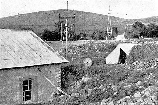
A branch line extends to Irapuato, the "Strawberry Station" on the Mexican Central Railway. The Irapuato sub-station is a brick building equipped with 60,000-volt disconnecting switches and lightning arresters and the following oil-insulated, air-cooled transformers: Four 200-kw line potential to 15,000 volts; four 75-kw, 15,000 to 460 volts, for motor service; two 40-kw, 15,000 to 2,200 volts, for the city lighting system. Power is supplied to various small industries throughout the city, including three grist mills, a foundry, a wagon works, a paint factory and various pumps used in irrigating the strawberry fields.
| |||
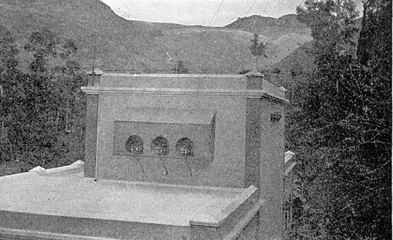
| Fig. 43. - Transmission Cables Entering Guanajuato Sub-Station. |
MISCELLANEOUS NOTES.
To the ingenuity of the American engineers, backed by American capital, is due' this noteworthy development by which the energy of the swift and boisterous Duero River has at last been harnessed, and after conversion into electricity has been transmitted over the 100 miles of intervening country to revivify the mining and other industries of the picturesque old city of Guanajuato, famous for its great mines, which are said to have produced, during the past 35 years, about one-fifth of all the silver in the world. Of late years these mines have not been worked to any great extent, largely because of the high cost of power.
There were many interesting as well as difficult features connected with the construction work. The task of hauling to the construction camp was by no means easy, although the distance was not more than ten miles. The way lay through the city of Zamora, thence to the little town of Jacona and thence about six miles along the State highway to the construction camp at the little Indian village of El Platanal, where the power-generating station is located. American mules were purchased and specially-designed American wagons were provided in order that adequate means should be at hand for carrying the heavy parts to their places.
| |||
| Fig. 44. - Front View of Guanajuato Sub-Station. |
The roads through the country are mostly over black adobe soil of indefinite depth. A few rainy days are sufficient to convert such roads into regular quagmires and put a stop to even such primitive means of transportation as are available in this locality. The haul through Zamora and Jacona was by far the worst part, since the streets had been "improved" by a pavement of stones of no small diameter; and in spite of the wide tires the wagons would break through the pavement into the underlying mud during the short intervals of time allowed for the animals to rest. It required a team of twenty-one mules to haul the lower half of the armature of one of the generators weighing 20,000 pounds. To get this load safely over the city streets required the combined efforts of two American superintendents and ten peons, all directly interested in some way in the moving of the load. Two wagons followed carrying jacks, block and tackle and tools for making repairs en route, forming in all quite a procession.
| |||
| Fig. 45. - the Irapuato Sub-Station. |
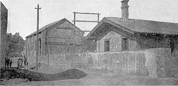
The handling and hauling of the pipe sections, weighing from 7,000 to 12,000 pounds each, a total of about 600 tons, was expeditiously completed, as shown. It is to the credit of the transportation organization that all of the hauling was done without the loss of or damage to a single piece of apparatus.
Carrying out a project of this magnitude in Mexico is made doubly difficult by the dense ignorance and absolute carelessness of the laboring class. The laborers, or peons, are mostly Indians or half-breeds, except where they are specially imported. These people wear as little clothing as possible, eat and drink whatever comes to hand, smoke cigarettes incessantly, are always ready to talk or play and are never ready to work. From time immemorable they have carried things on their backs, and it becomes necessary for the American to adapt himself to their ideas in order to get work done. It is exceedingly difficult, if not impossible, to teach them new methods of working. The customary method of handling dirt is by means of baskets or costals (a small piece of burlap) carried on the back. It is reported that when one contractor attempted to introduce the use of wheelbarrows, the peons preferred to carry the barrow, load and all, on their backs rather than learn how to wheel it on a runway. The wages paid to the laboring man vary from 40 cents to 60 cents per day (Mexican) if he be unskilled, 75 cents to $1.25 if he be a cabo (gang boss), and from $2.50 upward if he be a skilled artisan, and are unquestionably greater than he knows what to do with.
The short time in which this project was executed is most remarkable and is characteristic of the management. The preliminary examination was made in March and April, 1902, construction was begun in the fall of the same year, and in October, 1903, the plant was put into regular operation. This undoubtedly establishes a record in Mexico for rapid and efficient execution of construction work of a technical character and of considerable magnitude, especially in view of the fact that the work was completed within the estimates of cost.
