[Trade Journal]
Publication: Electrical World and Engineer
New York, NY, United States
vol. 44, no. 7, p. 245-247, col. 1-2
The Guanajuato, Mexico, Power TransmissionII.
BY ROBERT McF. DOBLE.
THE POWER HOUSE.
THE first part of this article dealt in very full detail with the hydraulic part of the Guanajuato transmission, up to the power house and the delivery of the water to the turbines. The power house itself and equipment will now be considered.
The inside dimensions of the power house are: length, 200 ft.; width, 32 ft. The floor is of cement. A low wall separates a length of 40 ft. at the easterly end of the building, where the transformers are placed, which portion is two feet lower than the main room, and is provided with drains into the tailrace. There are two ten-ton, hand-operated cranes, which run the entire length of the building over both generator and transformer rooms. The erection of these cranes was an unusually simple matter. They were rolled into place from the surface of the ground and subsequently constituted the basis of a movable platform upon which the roof trusses were carried to place.
| |||
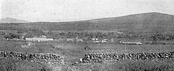
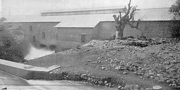
| Fig. 24.- Power House As Seen From the Pipeline. |
| |||
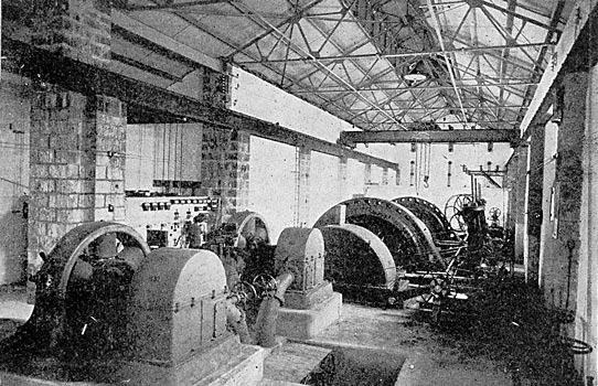
| Fig. 25.-The Guanajuato Generating Plant. |
The cast-iron branch pipes convey the water to heavy 30-in. gate valves equipped with by-passes. The nozzles are attached to the gate valves, as shown in the accompanying plan. These pipes are made of close-grained gray cast iron and have lip and recess bolted flange joints with lead gaskets and are entirely buried in concrete. The nozzles are curved in form, making a 45° bend, so as to bring the axis of the jet at right angles to the water wheel shaft. Each nozzle is provided with a removable tip, of cold blast charcoal iron, held in place by means of 14-7/8-in. Tobin bronze studs with steel nuts. The nozzle is of the needle regulating type, having a core piece movable axially within it by means of which the annular area of the orifice is changed. The core piece is a Tobin bronze stem with a phosphor bronze bulb fitting into the nozzle tip. A continuation of the stem through a gland in the convex side of the nozzle casting is threaded, and, by means of a bevel gear nut operated through a hand wheel stand, the needle is moved in and out to adjust the quantity of water discharged by the nozzle, so that the maximum economy in the use of water may be attained. This construction produces a solid jet of good form and of high efficiency over a wide range of discharge. Each nozzle is equipped with a deflecting hood, operated through a system of levers by a governor, for regulating the speed of the generating unit.
| |||
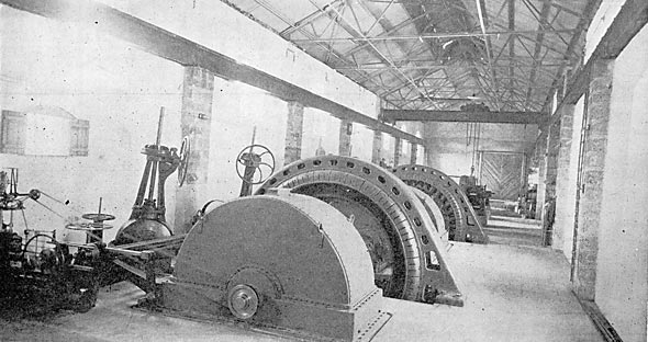
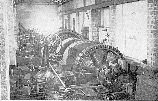
| Fig. 26.-View of Turbines in Generating Plant. |
The water emerging from the nozzle tips in solid jets more than half a foot in diameter at a velocity exceeding a mile and a half per minute, with a pressure of 138 pounds per sq. in., is projected into the buckets of the water wheels. The discharge into the tailrace and the Tamandaro aqueduct over the tailrace are shown in some of the views in the earlier part of this article.
Each water wheel has 15 huge buckets, more than 2 ft. in width and weighing 254 pounds apiece, made of close-grained, cold-blast charcoal iron. The buckets are accurately fitted to the rim of the cast-iron wheel center and secured thereto by means of two fitted steel stud bolts. The entrance edges are sharpened, the hydraulic surfaces are ground smooth and painted, and each bucket is brought to a standard weight so as to obtain a dynamic balance. The cast-iron wheel centers are machine-finished all over, bored taper, key-seated and secured onto the projecting ends of the generator shafts by means of a feather and a large bronze nut, as shown by the longitudinal partial section. The solid carbon steel shaft is 12 in. in diameter from the water wheels through the bearings, being enlarged to 16 in. diameter in the middle portion. The bearings are 36 in. in length by 12 in. in diameter, of ring-oiling, water-cooled type of special design.
| |||
| Fig. 27.-Exterior View of Guanajuuato Power House, Showing Tailrace |
The generators are revolving-field, engine type, 2,300-volt, three-phase, 60-cycle, 200-r.p.m. machines, rated at 1,250 kw, but designed for a 25 per cent. continuous overload. Their characteristics, as determined by factory test, are as follows: Full-load commercial efficiency, 95.77 per cent.; three-fourths load, 94.92 per cent.
Regulation at full load and 100 per cent. power factor is 4.4 per cent.; temperature rise of armature, 21° C., after 6 hours' full-load operation.
The total weight of the revolving element, consisting of the field, the shaft and the two water wheels, is about 50,000 pounds, carried on two bearings. The speed is regulated by means of a governor, operated by an oil pressure system, actuating the deflecting hoods already described. The governors and the oil pressure pumps are belted from the generator shaft.
| |||
| Fig. 28.-Power House Under Construction Looking West. |
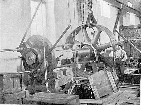
The General Electric generating units above described are conspicuous by reason of their compactness and simplicity, there being only the stationary armature, the electric and hydraulic revolving elements mounted on the shaft, and two bearings. The 1,250-kw unit occupies a floor space of only about 17 ft. by 25 ft. The assembling of such heavy machinery remote from shop facilities presented some difficulties, and in one of the engravings is shown the method employed for pulling on the revolving-field spider and the water wheels by use of specially long threaded steel bolts.
Continuous current for exciting the alternators is supplied by two 120-kw, 500-r.p.m., self-contained hydro-electric units, each of sufficient capacity to excite the four generators, so that one exciter is a spare. The exciter base is extended so as to receive the water wheel housing. The water wheel is mounted on the extended end of the shaft overhanging the bearing. Water is supplied to the wheel through a hand-regulating needle nozzle, being conveyed from the main branch pipe, as shown by the plan.
| |||
| Fig. 29.-Putting Generator Spider and Turbine Center on the Shaft. |
The current is conveyed from the generators to the switchboard, and thence to the step-up transformers, through lead-covered, rubber?insulated copper cables laid in shallow-covered ducts in the cement floor. The current passes from the generators through 600-amp., oil-break switches, each installed in a separate concrete compartment, to the 2,300-volt bus-bars.
The field rheostats are supported on I-beams above the switchboard and are operated by means of chains and sprocket wheels. The bus-bars, oil switches and wiring for the instruments are all back of the board and out of the way, being located in an alcove on the north side of the building, as shown in the plan and in photographs. The switchboard has seven marble panels, one for each of the generators, one for each exciter and one for two step-up transformer circuits.
[missing text in original article] reasonable price anyone may obtain the results of careful tests made by acknowledged experts.
From the switchboard the 2,300-volt current is conducted to the 1,080-kw static transformers, where the potential is raised to 60,000) volts for transmission. The transformers are delta-connected on the low-potential side and Y-connected on the high-potential side, having taps brought out through the top of the tank for line potentials of 40,000, 50,000 and 60,000 volts, the neutral being grounded.
 |
| Fig. 30.Cross-Section of Generating Plant. |
The efficiencies of the transformers as determined by factory tests are as follows: Full load, 98.295 per cent.; three-fourths load, 98.028 per cent. The transformers are of the oil-insulated, water-cooled type; the tanks are 12 ft. in height and occupy a floor space of 3 ft. by 6 ft.
 |
| Fig. 31.Longitudinal Partial Section of Generator Room. |
From the step-up transformers the current is conducted to the transmission line, the wires passing out of the building through circular openings in the wall to a set of 60,000-volt disconnecting switches, mounted just outside of the building and thence to the first tower of the transmission line.
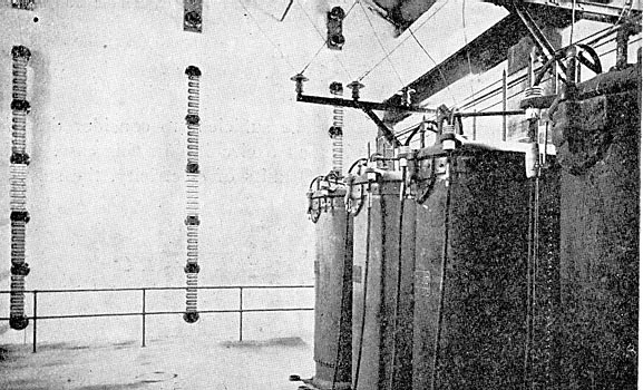
On the inside wall of the building three rows of 60,000-volt lightning arresters are mounted, being connected through switches to the outgoing leads.
| |||
| Fig. 32.-Transformer Room at Power House. |