[Trade Journal]
Publication: Electrical World and Engineer
New York, NY, United States
vol. 46, no. 1, p. 14-15, col. 1-2
Transmission of Niagara Power to Toronto. I.
TWO lines of steel towers on a private right of way 75 miles long are to carry four circuits for the transmission of 40,000 horse-power at 60,000 volts from Niagara Falls to Toronto.
On this right of way the minimum standard width is 80 feet, the grade toward Toronto is not expected to exceed 15 feet per mile, and toward Niagara Falls 53 feet per mile, and the rate of curvature will not be more than 3-1/2 degrees, or a radius of 1,637 feet. These figures for grade and curvature are especially important because a high-speed electric railway is to be operated with double tracks between the two rows of steel towers along the entire length of the line.
Between the two lines of towers the clear width of the right of way is 34 feet, the centers of the double tracks are 13 feet apart, and the distance from the center of each track to the sides of the nearer towers is also 13 feet. From the center of each tower to that of the right of way is 24 feet, and the two lines of towers thus have their centers 48 feet apart. At the ground line the width from outside to outside of the tower lines is 62 feet, but at the level of the crossarms the width is 67 feet 6 inches. At present one line of these towers with its two transmission circuits is nearly completed, and the other line of towers will be erected as soon as the demand for power makes it desirable.
On the straight portions of the line the steel towers are regularly erected 400 feet apart, but on curves the distances are less between towers, so that their total number is about 1,400 for each line. Standard curving along the line requires towers placed 50 feet apart, and a change in direction of not more than 10 degrees at each tower, except at the beginning and end of the curve where the change in direction is 3 degrees. When the change in direction of the line is not more than 6 degrees the corresponding spans allowed with each change are as follows:
| |||
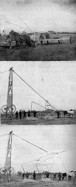
| Figs. 1, 2, and 3. Raising Towers on Niagara Transmission Line. |
If the line follows a rising grade with a span of zoo feet the elevation of the first tower beyond the level may be 7 feet above the one preceding, the elevation of the second tower 14 feet, with 21 feet rise between the second and third tower, 28 feet between the third and fourth, and a line that follows an up grade with a span of 300 feet may rise 24 feet in the first span beyond the level, 48 feet in a distance of 400 feet between towers, the rise of the first span beyond the level may be as much as 56 feet, of the second 112 feet, of the third 168 feet, and so on.
| |||
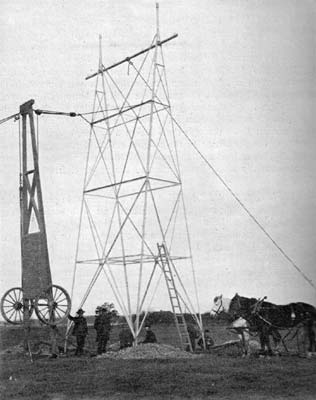
| Fig. 4. - One of the Towers in Position. |
At the same points along the line conditions require a span between towers of more than 400 feet, the regular distance for straight work. One example of this sort occurs at Twelve Mile Creek, where the stream has cut a wide, deep gorge in the Erie plateau. At this point the lines makes a span of 625 feet between towers. In the case of this long span, as in some others, it is not thought desirable to have the transmission circuits at either side of the electric railway, and the right of way is therefore widened so that the towers can be set at one side. For the crossing at Twelve Mile Creek the center line of the nearer line of towers is moved to a distance of 63 feet to one side of the center line of the electric railway, and the distance between the centers of the two lines of towers is reduced to 30 feet. To provide for this sharp offset a special form of tower is provided.
| |||
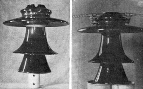
| Fig. 5. - Insulators. |
The regular steel tower used in this transmission measures 46 feet in vertical height from its foot to the top of the lower insulators, and 51 feet 3 inches to the tops of the higher insulators. The lower six feet of this tower are embedded in the ground, so that the tops of the insulators measure about 40 feet and 45 feet 3 inches respectively above the earth. At the ground the tower measures 14 feet at right angles to the transmission line, and 12 feet parallel with it. The width of each tower at the top is 12 feet at right angles to the line, and the two sides having this width come together at points about 40 feet above the ground. Between the two L bars thus brought nearly together at each side of a tower a piece of extra heavy 3-inch steel pipe is bolted so as to stand in a vertical position. Each piece of this pipe is about 3-1/2 feet long and carries a steel insulator pin at its upper end. The two pieces of pipe thus fixed on opposite sides of the top of a tower carry the two highest insulators. For the other four insulators of each tower pins are fixed on a piece of standard 4-inch pipe that serves as a crossarm, and is bolted in a horizontal position between the two nearly rectangular sides of each tower, at a point two feet below the bolts that hold the vertical 3-inch pipes already named in position. Save for the two short vertical and one horizontal pipe, and the pins they support, each tower is made up of L-shaped angle bars bolted together. Each of the two nearly rectangular sides of a tower consists of two L bars at its two edges, three L bars for cross braces at right angles to the edges, and four diagonal braces also formed of L bars. The lower halves of the L bars at the edges of each side of a tower have sections of 3" x 3" x 1/4", and the upper halves have sections of 3" x 3" x 3/16". This last reamed cross brace, and the other two cross braces have a common section of 2" x 1/2" x 1/8". For the lower set of diagonal braces the common section is 2-1/2" x 2" x 1/8", and the upper set has a section of 2" x 1-1/2" x 1/8" in each member. At the level of the lowest cross braces the two rectangular sides of a tower are tied together by one member of 2" x 1-1/2" x 1/8" of L section and at right angles to the sides, and by two diagonal braces of 5/8" round rod between the corners of the tower. On each of its two triangular sides a tower has four horizontal braces, and three sets of diagonal braces. The two upper horizontal braces are of 2" x 1-1/2" x 1/8" L section, and the lowest is the same, but the remaining horizontal brace has a section of 2-1/2" x 2" x 1/8". Bars of 2" x 1-1/2" x 1/8" L section are used for the two upper sets of diagonal braces, and bars of 2-1/2" x 2" x 1/8" for the lower set. In addition to the cross braces named, each triangular side of a tower near the top of the corner bars has two short cross pieces with the common L section of 3-1/2" x 3-1/2" x 5/8", one just above and the other just below the crossarm of 4-inch pipe to hold it in place. At the bottom of each of the four corner bars of a tower a foot is formed by riveting a piece of 3" x 1/4" L section and 15 inches long at right angles to the corner bar. On one corner bar of each tower there are two rows of steel studs for steps, one row being located in each flange of the L section. On the same flange these steps are 2 feet apart, but taking both flanges they are only one foot apart. Every part of each steel tower is heavily galvanized.
| |||
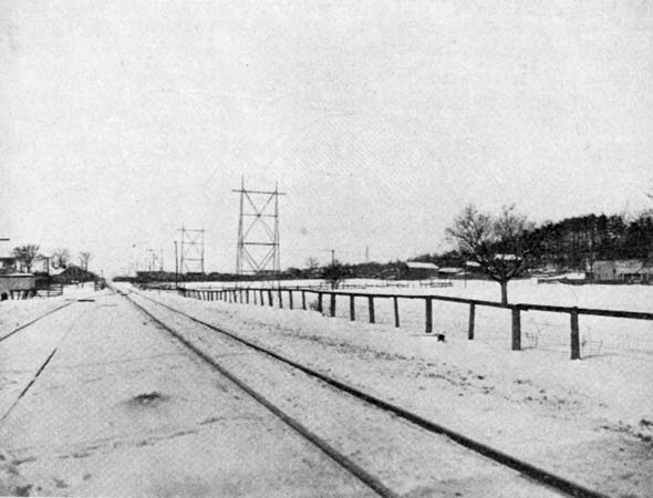
| Fig. 6. - General View Along Niagara Transmission Line. |
The labor of erecting these steel towers has been reduced to a low figure by the method employed, as shown in the accompanying illustration. Each tower is brought to the place where it is to stand with all of its parts assembled, save that the extensions of the legs that go into the ground are detached. These extension pieces are first fixed in the ground with their ends projecting to receive the legs of the tower. For hauling the towers a four-wheel wagon with a timber body about 30 feet long is used. When it is desired to raise a tower, two of the wheels with their axle are detached from the timber body of the wagon, and this body is then stood on end to serve as a sort of derrick. This derrick is guyed at its top on the side away from the tower, and a set of blocks and tackle is then connected to the top of the derrick and to the tower at a point about one-fourth of the distance down from its top. A rope from this set of blocks runs through a single block fixed to the base of the derrick and then to a team of horses. On driving these horses away from the derrick the steel tower is gradually raised on the two legs of one of its rectangular sides until it comes to a vertical position. The next operation is to bring the legs of the tower into contact with the extension pieces that are fixed in the earth, and then bolt them together.
