[Trade Journal]
Publication: Electrical World and Engineer
New York, NY, United States
vol. 46, no. 2, p. 54-56, col. 1-2
Transmission of Power from Niagara to Toronto.II.
(Concluded.)
THE tops of the three pins that carry the insulators for each three-phase circuit are at the corners of an equilateral triangle (Fig. 7), each of whose sides measures six feet. The six steel insulator pins used on each tower are exactly alike, and each is swaged from extra heavy pipe. Each finished pin is 2 3/8 in. in diameter for a length of 3 1/4 in., and then tapers uniformly to a diameter of 1 1/8 in. at the top through a length of 11 1/2 in This gives the pin a total length of 14 3/4 in. In the larger part there are two 9-16 in. holes from side to side, and within two inches of the top there are three circular grooves each 3-16-in. wide and 1-16-in. deep. Forged steel sockets of two types are employed to attach the steel pins with the pipes. Each socket is made in halves, and these halves are secured to both the pipes and the pins by through bolts. Like all other parts of the towers these steel pins and sockets are heavily galvanized. On each of the four corner bars of a tower the lower six feet of its length is secured to the upper part by bolts. This lower six feet of each corner bar is embedded in the earth, and the construction just named makes it easy to replace the bars in the earth when corrosion makes it necessary.
 |
| Fig. 7.Steel Tower for Transmission Line. |
Footings for each tower were provided by digging four nearly square holes with their sides at approximately 45 degrees with the direction of the transmission line, and the shortest side of each hole at least two feet long. Centers of these holes are 14 ft. 3 in. apart, in a direction at right angles to the line, and 13 ft. 9 in. apart, parallel with the line. In hard pan each one of the holes was filled to within 2 ft. 6 in. of the top with stones, after the leg of the tower was in position, and then the remainder of the hole was filled with cement grouting mixed four to one.
At the bottom of each hole in marsh land a wooden footing 3 ft.x 6 in.x24 in. was laid flat beneath the leg of the tower, and then the hole was filled to within 2 1/2 ft. of the surface with the excavated material. Next above this filling comes a galvanized iron gutter pipe, 4 in. in diameter, and filled with cement about the leg of the tower for a length of two feet. Outside of this pipe the hole is made rounding full of cement grouting.
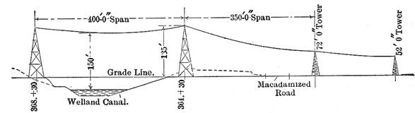
At some points along the transmission line exceptionally high towers are necessary, a notable instance being found at the crossing over the Welland Canal, where the lowest part of each span must be not less than 150 feet above the water. For this crossing two towers 135 ft. high above ground are used, as seen in Fig. 8.
 |
| Fig. 8.Steel Tower for Transmission Line. |
Each of these towers is designed to carry all four of the three-phase power circuits that are eventually to be erected between Niagara Falls and Toronto. For this purpose there was used a special design of tower with a width of about 48 ft. at right angles to the direction of the line below the top truss, and a width of about 68.5 ft. at that truss where the two lower conductors of each circuit are attached.
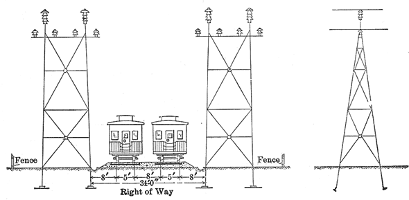
With all spans longer than 400 ft. a tower of heavier construction than the standard type is used, and this tower provides three insulators for the support of each conductor. A tower of this type that supports the lowest conductors about 40 ft. above the ground level has its corner bars made up of 4-in.x 4-in.x 3/8-in. and 4-in.x 4-in.x 5-16-in. L sections, has three cross-arms of extra heavy 4-in. pipe, and a 6-in. vertical standard pipe to support each group of three insulators for the highest conductor of each circuit. Each of the lower conductors of a circuit on this tower is supported by an insulator on each of the three parallel cross-arms. On some of these towers, for long spans, the two outside insulators for the support of each conductor are set a little lower than the insulator between them.
Angle towers, used where the line makes a large change in direction at a single point, have three legs on each rectangular side, a width of 20 ft. on each of these sides for some distance above the ground, and a width 27 ft. 2 in. at the top. In these towers the two legs on the triangular side that is in compression are each made up of four 3-in.x3-in.x1/4-in. L sections, joined by 1 1/2-in.x 1/4-in. lattices and rivets. Towers of this sort are used near the Toronto terminal station, where the line changes 35 degrees at a single point, and near the crossing of Twelve Mile Creek, where the angular change of the line on a tower is 45 degrees. Close to each terminal station and division house the transmission line .is supported by terminal towers. These towers differ from the others in that each carries insulators for only three conductors, and these insulators are all at the same level. Each terminal tower has nine insulators, arranged in three parallel rows of three each, for the conductors of a single circuit, and each conductor thus has its strain distributed between three pins. All three wires of a circuit are held 40 feet above the ground by a terminal tower, and pass to their entries in the wall of a station at the same level. As these terminal towers must resist the end strain of the line they are made extra heavy, the four logs each being made up of 4-in.x4-inx 5-16-in. and 4-in.x4-in.x3/8-in. L sections. For the three cross-arms on one of these towers three pieces of 4-in. pipe, each 15 ft. 9 in. long, are secured at its top with their parallel center lines 30 in. apart in the same plane. Each of these pipes carries three insulator pins with their centres 7 ft. 4 l/2 in. apart. On the bottom of each leg of a terminal tower there is a foot, formed by riveting on bent plates, that measures 15 and 18 in., respectively, on its two longer sides. Each foot of this tower is set in a block of concrete 5 feet square that extends from 3.5 ft. to 7.5 ft. below the ground level.
Insulators for the transmission line, which are illustrated in Fig. 5, are of brown, glazed porcelain, made in three parts, and cemented together. The three parts consist of three petticoats or thimbles, each of which slips over or into one of the others, so that there are three outside surfaces and three interior or protected surfaces between the top of an insulator and its pin.
From top to bottom the height of each insulator is 14 in., and this is also the diameter of the highest and largest petticoat. The next or middle petticoat has a maximum diameter of 10 in., and the lowest petticoat one of 8 in. Cement holds the lowest petticoat of the insulator on one of the steel pins previously described, and in this position the edge of the lowest petticoat is about 2 1/2 in. from the steel support. At the top of each insulator the transmission conductor is secured, and the shortest distance from this conductor to any of the steel parts through the air is about 17 in.
From the step-up transformer house at Niagara Falls to the terminal station at Toronto, a distance of 75 miles, each three-phase, 60,000-volt, 25-cycle circuit on the steel towers is made up of three hard-drawn copper cables with a cross section of 190,000 circular mils each, and is designed to deliver 10,000 electric horsepower. Six equal strands of copper make up each cable, and this wire has been specially drawn with an elastic limit of more than 35,000 pounds, and a tensile strength of over 55,000 pounds per square inch. This cable is made in uniform lengths of 3,000 ft., and these lengths are joined by twisting their ends together in cooper sleeves, and no solder is used. No insulation is used on these cables.
Instead of a tie wire a novel combination of clamps is employed to secure the copper cable on each insulator. This clamp is made up of two separate clamps that grasp the cable at opposite sides of each insulator, and of two half circles of hard-drawn copper wire of 0.187 in. diameter. Each half circle of this wire joins one-half of each of the opposite clamps, and fits about the neck of the insulator just below its head. Two bronze castings, one of which has a bolt extension that passes through the other, and a nut, make up each separate clamp. When the combined clamp is to be applied as quickly as a tie wire, is very strong, and does not cut side are separated by removing the nut that holds them together, the half circles are brought around the neck of the insulator and each of the side clamps is then tightened on to the cable by turning the nut that draws its halves together. This complete clamp can be applied as quickly as a tie wire, is very strong and does not cut into the cable.
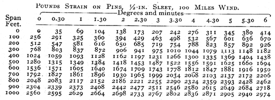
Each of the regular steel towers is designed to withstand safely a side strain of 10,000 pounds at the insulators, or an average of 1,666 pounds per cable. With the 190,000 mil cable coated to a depth of 1/2-in. with ice and exposed to a wind blowing 100 miles per hour, the estimated strains on each steel pin for different spans and angular changes in the direction of the line are given in the accompanying table:
 |
The copper cables were so strung as .to have a minimum distance from the ground of 25 ft. at the lowest points of the spans. In order to do this the standard steel towers that hold the lower cables 40 feet above the ground level at the insulators are spaced at varying distances apart, according to the nature of the ground between them. At each tower the upper cable of each circuit is 5 ft. 3 in. higher than the two lower cables, and this distance between the elevations of the upper and the lower cables is maintained whatever the amount of sag at the center of each span. If there is a depression between two standard towers on a straight portion of the line the sag in the center of a span 40o ft. long may be as much as 18 ft. Where a rise and fall in the ground between towers makes it necessary to limit the sag to 14 ft. in order to keep the lowest cables 25 ft. above the highest point of earth, the length of span is limited to 350 ft. If the rise and fall of ground level between towers allows a sag of only 11 ft. with the lowest cable 25 ft. above the earth, the length of span with 40-ft. towers -is reduced to 300 ft., and if for a like reason the sag is limited to 8 ft. the span may only be 250 ft.
 |
| Fig. 9.Take-Up Arrangement on Terminal Tower. |
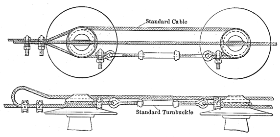
At each terminal tower, where the cables are secured before they pass into a terminal station, the three insulators for each cable are in a straight line with their centers 30 in. apart. When a line cable reaches the first insulator of the three to which it is to be attached on one of these towers it is passed around the neck of this insulator and then secured on itself by means of two clamps that are tightened with bolts and nuts. See Fig. 9. The cable thus secured turns up and back over the tops of its three insulators and goes to the terminal station. Around the neck of the insulator to which the line cable has been secured in the way just outlined a short detached length of the regular copper cable with the parts of a turnbuckle at each end is passed, and this same piece of cable also passes around the neck of the next insulator in the series of three. By joining the ends of the turnbuckle and tightening it, a part of the strain of the line cable in question is transferred from the first to the second insulator of its series. In the same way a part of the strain of this same line cable is transferred from the second insulator of the series to the third or one nearest to the terminal station.
From its insulators on a terminal tower each line cable passes to an insulator at the same level on a steel bracket outside of the terminal station. After leaving this insulator on the bracket the line cable turns up and goes through a bushing set in the bottom of a metal box or hood that is fixed on the outside of the terminal station above the steel bracket, as shown in Fig. 10. Having reached the inside of this metal hood the line cable makes another right-angle turn and goes through the center of a 4o-in. by 36-in. opening in the brick wall of the terminal station. At the center of this square opening the line cable is supported by one of the porcelain insulators regularly used outside. The hood just mentioned is made of expanded metal covered with cement.
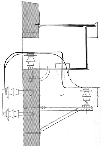 |
| Fig. 10.Cable Entering Building. |
From the line cable to the steel socket of the pin on the bucket the shortest distance through the air is about 17 in., and this is also the distance from the cable to the metal hood. Between the line cable and the brick wall outside of the metal hood the distance is about 25 in. At the upper outside edge of the hood there is a gutter that prevents the dripping of water on to the insulators and line cables below. Of the two insulating bushings through which a line cable passes to enter the metal hood the inner one has an outside diameter of 3 in. and a length of 24 in., and the outer one a diameter of 13 in. and a length of 12 in. The three rectangular openings in the brick Wall of the terminal station for the entry of the line cables of each 60,000-volt circuit are at the same level, and have their centers 7 ft. 4 1/2 in. apart. From the nearest opening of one circuit to the nearest opening of another circuit in the wall of the Toronto terminal station the distance between centers is 29 ft.
At one or more points on the transmission line there is a division house through which the circuits pass. The object of this division house is to make easy the connection of any circuit between the house and Niagara Falls with any circuit between the house and Toronto. This is done by means of two sets of three-phase busbars to each of which either circuit may be connected by switches. The scheme of connections is shown in Fig. 11. Each division house includes a pair of duplicate brick buildings joined by a gallery for busbar connections. Into each of these duplicate buildings two of the three-phase circuits pass. Each of these buildings, exclusive of the gallery for busbar connections, measures 58 ft. at right angles to the direction of the transmission line, and 34 ft. parallel therewith, outside, and is 48.5 ft. high. Structural materials in the building are brick, stone, steel and concrete. On each of the longer sides of this division house, and with their centers 12 ft. from it, there are two of the 4o ft. steel terminal towers previously described.
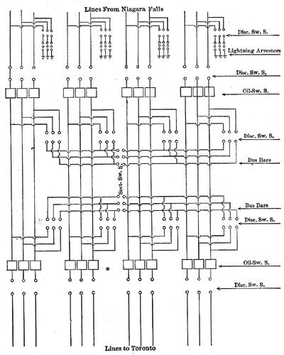 |
| Fig. 11.Circuits at Division House. |
The present portion of the complete division house provides for two of the three-phase circuits, and when the other two circuits are erected the remainder of the division house will be built. For this remainder the brick building will be exactly like the one just named, and the two buildings will be connected by a busbar gallery of steel and masonry 34 ft. long. In this gallery there will be sectional switches by which each of the six busbars in the two three-phase sets can be divided.
Each line cable entering at one side of the division house connects through one knife switch with a bank of lightning arresters, and through another knife switch with one pole of a three-phase oil switch. From this same pole of the oil switch a cable runs to the corresponding pole of another oil switch that connects through a knife switch with a line cable that enters on the opposite side of the division house from the cable first named. In this way each line cable may have its connection completed in the division house through two knife switches and two oil switches, without coming into contact with the busbars. When each transmission circuit passes directly through the division house in this way the busbars are entirely out of use. If it is desired to connect that part of a circuit between Niagara Falls and the division house with the part of another circuit between the division house and Toronto, this can be done by joining the two parts of circuits to the same set of bus-bars through knife switches. By means-of such knife switches any cable between two poles of different oil switches in the division house can be connected to one busbar of either of the two three-phase sets.
On the inside the division house has two rooms in the first story, formed by a 13-in. brick wall at right angles to the direction of the line, and each of these rooms contains one set of busbar compartments. Besides the busbars one of these rooms also contains the lightning arresters. In the upper story of the house the two groups of oil switches stand on a steel and concrete floor.
The Toronto & Niagara Power Company, which is making this first really long transmission of electric energy from Niagara Falls, has for its president Col. H. M. Pellatt, and first vice-president and general manager Mr. Frederic Nicholls. Dr. F. S. Pearson is chief consulting engineer for the company, and Mr. Robert C. Brown is chief electrical engineer. The facts here presented have been collected through the personal kindness of Mr. Nicholls and Mr. Brown.
