[Trade Journal]
Publication: Electrical World and Engineer
New York, NY, United States
vol. 46, no. 12, p. 479-481, col. 1-2
Along the Niagara -Toronto Transmission Line.
SIX hand drawn copper cables, each of 190,000 circular mils cross section, now stretch over a line of steel towers 75 miles long between a terminal station at Niagara Falls and another at Toronto. In a few weeks the two circuits formed by these cables will be delivering energy generated by Niagara water to the electric lighting, power and street car systems of the second city of Canada.
A general description has been given in these columns of the design and construction of this transmission line, which, by reason of its length, the voltage employed, the amount of power to be delivered, and its steel towers, is one of the most notable in the world. Now it is possible to add some details as to the completed line work. Each of the two groups of three conductors on the steel towers forms a three-phase circuit, which is designed to receive current at 60,000 volts from Niagara Falls, and to deliver 12,000 horse-power in Toronto with a loss of 20 per cent in voltage. A loss of 20 per cent in voltage on the line will be incurred at times, and under these conditions the two circuits will deliver about 43,000 horse-power, with a zoo per cent. power factor.
| |||
| Fig. 1. Angle Tower Near Bronte. |
| |||
| Fig. 2. Long Span Near Bronte. |
In its 75-mile course the transmission line of steel and copper takes an outline like the string of a well drawn bow, with the ends at Niagara Falls and Toronto, and the center near the western end of Lake Ontario, which is known as Burlington Bay. Along almost its entire length the line traverses the watershed of the lake approximately parallel with its shore, and thus crosses the numerous creeks that flow into it between the Welland Canal and Toronto. The streams of which these creeks are now only feeble remnants, have in past ages cut wide and deep gorges in the high lands that run back from the lake, and in several instances extra long spans have been necessary at such crossings. About seven miles from Niagara Falls the line crosses the Welland Canal on towers that carry the conductors 150 feet above the water, and on these high towers lightning rods are used. Ten miles from the Niagara terminal station the line begins to verge toward the shore of the lake, and reaches the brow of the escarpment after a run of 29.6 miles, at a point a little beyond Grimsby. From this point to the 35th mile the line carries a galvanized steel cable above the copper conductors as a lightning guard wire. This cable is secured at the top of a central extension of the steel tower which holds it seven feet above the nearest copper conductors. Though resting on the steel work of the towers, the guard cable is more effectively grounded at intervals.
 |
| Fig. 3. Sections and Plans, Toronto Terminal Station. |
| |||
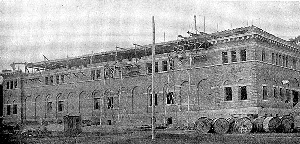
| Fig. 5. Toronto Terminal Station and Anchor Towers. |
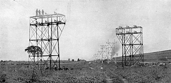
By following the narrow neck of land known as Burlington Beach, which separates Burlington Bay from the main body of the lake, the line avoids a course around its extreme west end, and thus saves several miles in length. For purposes of navigation to the city of Hamilton, near the head of the lake, a canal cuts Burlington Beach, and the circuits cross this canal high above the water. On the north shore of Lake Ontario, near Bronte, the line crosses the gorge of Twelve Mile Creek with a span 630 ft. long. The steel towers at the ends of this span are of extra heavy construction, and each tower carries three insulators in line for the support of each copper cable.
| |||
| Fig. 4. Heavy Tower at Credit River. |
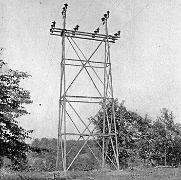
About two miles west of Bronte comes the crossing of the transmission line over the Great Western Railway, and at either end of the crossing over Twelve Mile Creek a pair of angle towers is used to increase the distance between the conductors and the railway. From the fiftieth to the sixtieth mile of its length from the Niagara Falls end, the transmission line runs over a right of way that adjoins that of the railway, and in this section are the crossings of both Twelve Mile and Sixteen Mile Creek. At 63.8 miles from the Niagara terminal is the crossing of River Credit where the span between towers is 766 ft. The tower at each end of this span, like those at Twelve Mile Creek, is of extra heavy construction, carries three crossarms in the same plane, and has three insulators in line for each copper cable.
 |
| Fig. 6. Map of Route of Transmission Line. |
As it nears Toronto the transmission line swings away from the lake shore, and reaches its terminal station on the northern boundary of the city, which is the side farthest from the harbor. Close to this terminal station are the two anchor towers, one for each three-phase circuit, which take the strain of the line before it reaches the entrance hood.
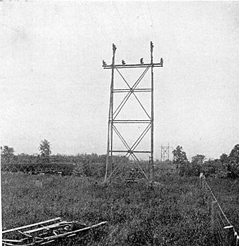
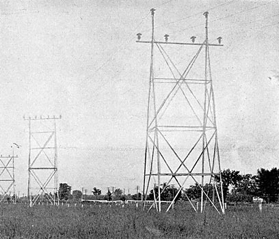
The way in which transpositions of the conductors are carried out along the line is illustrated in Fig. 7, where it may be seen that the transposition tower, the second one in view, has two cross arms instead of one like the standard towers, and carries two wires of each circuit above the third. From the fiftieth to the sixtieth mile, approximately, of the transmission line, where it runs close to and parallel with the railway, the transpositions of the conductors is more frequent than elsewhere, and there are four complete spirals in that section. Three division houses are so located along the line as to cut it into four nearly equal sections. One of these division houses is about 19 miles, another about 40 miles, and the third about 61 miles from the Niagara end of the line.
| |||
| Fig. 7. Transmission Tower (Second Tower). |
Through each division house pass the two three-phase circuits, and the switches there make it possible to connect any conductor in the section of the line on one side of the house with any conductor on the other side. Each conductor in a division house is connected with a lightning arrester made for 60,000 volts by the General Electric Company. This lightning arrester contains 240 air-gaps between brass cylinders, and 60 carborundum rods, all in series from the line cable to the earth. A complete lightning arrester as just described is mounted on porcelain line insulators, is 25 1/2 in. wide and 19 ft. long.
Each tower has a good ground connection and it will probably act to some extent to protect the line against an actual stroke of lightning. It is evident, however, that the towers cannot be depended upon as a protection against static and inductive influences, and the lightning arresters are just as necessary on steel as on wooden poles. It is believed that the guard cable, mentioned previously, and the arresters will furnish adequate protection for the line.
To Dr. F. S. Pearson, Consulting Engineer of the Toronto and Niagara Power Company, which is carrying out this transmission to Toronto, and to Mr. Robert C. Brown, Chief Electrical Engineer of that company, are due acknowledgments for the above facts.
 |
| Fig. 8. Elevations and Plan of Tower. |
