[Trade Journal]
Publication: The Engineer
London, England
p. 329-330, col. 2, 3, 1-3
THE INSULATION OF OVERHEAD LINES.
By W. B. ESSON, M. Inst. C.E., M.I.E.E.
No. 1
As there is every likelihood of our seeing a considerable amount of electric power transmitted through overhead lines, in this country, in the near future, an article dealing with the insulation of such lines may prove of interest.
The insulation of the line is, in power transmission work, of paramount importance, and it need scarcely be said that the need for careful study of the circumstances which influence it becomes greater as working pressures become higher. The evolution of the insulator is not the least interesting part of electric power history, for it is only by continuous experiment during the past fourteen years, and constant modification to meet the different conditions which have from time to time arisen, that the present excellence of insulation has been achieved.
At the present time insulators are made in one of two materialsglass or porcelainthe former being used very largely in America, while in Europe the latter is used almost exclusively. This circumstance seems to have arisen more from accident than anything else, and both materials have given very satisfactory service, though it is now admitted that, upon the whole, porcelain has superior claims to glass. The degree of insulation attained depends upon the climatic conditions of the locality as well as on the insulators, and it has been frequently urged that glass would not do in this country because of its being so hygroscopic. For this reason glass may have been found unsuitable for telegraph work, but the objection does not apply with the same force to power work, as, when the current is put on the line, any condensation on the insulators is very soon dried up by the small amount which at first leaks over the surface. At the same time, to avoid possible cracking of the insulators, the precaution of raising the pressure gradually should always be adopted if the atmosphere is of a humid character. From the elaborate comparison of different insulators he made in America, Mr. Ralph D. Mershon concluded that those of glass were preferable to those of porcelain. He gave as his reasons that they were cheaper, lighter, more easily tested, and less likely to form targets for marksmanship.
In this law-abiding country, where people do not as a rule carry shot guns and revolvers, the last reason would not apply to the same degree; but it is worthy of note that one of the largest manufacturing firms in the States coats its porcelain insulators with a brown glaze unless otherwise ordered for the express purpose of rendering them as invisible as possible. The dielectric resistance of glass Mr. Mershon found to be as high as porcelain, and so far as measurements up to 60,000 volts showed, there was no difference in the hygroscopic properties of the materials. Though possibly more uniform in quality than porcelain, glass, if not properly annealed, is, due to unequal strains in different parts, very liable to fly. A hot sun after a cool night will often cause breakage, and due to improper annealing there have been cases of the heads coining off the insulators, and the wires coming down in consequence.
One point in favour of glass is that testing is easier. It is held by several engineers that if from a consignment of insulators a few samples selected at random stand the high voltage electrical tests, the testing of the remainder is unnecessary, visual inspection revealing any cracks, bubbles, or pits, that would impair the dielectric quality of the insulators, reduce their strength or trap moisture. The failure of glass due to puncture after visual inspection and tapping with a mallet is said to be rare, but whether it is wise to trust in this way to the bulk turning out all right is an open question. However this may be, it is necessary to put every porcelain insulator through the high voltage test, and not only so, but careful examination must be made to see that the glaze is perfect. Glaze does not in itself add to the insulation of highly-vitrified porcelain, but dirt sticks to any unglazed or imperfectly glazed portion of the surface, and to ensure the absolute external smoothness, which is essential, insulators are always supported from the bottom during the firing process. There is no doubt that porcelain has superior mechanical strength, and can better stand severe weather conditions than can glass, and notwithstanding that glass is working successfully on 60,000 volt lines, there is a distinct tendency to favour porcelain in America for all new work. The insulators described in this article are all mode of porcelain, but it may be mentioned that whichever of the two materials is used, for lines working under similar conditions the same size and shape of insulator is required.
 |
| Overhead Electric Insulators |
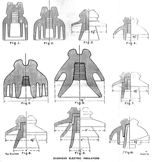
Naturally the telegraph insulator gave to the power insulator its early form. Before the days of power transmission the great superiority of the double shed over the single shed insulator had been proved in telegraph work, accordingly an insulator of the latter class, but of larger size, soon found its place for high-pressure work on overhead lines. The obvious way of providing for higher pressures was to add another concentric shed or petticoat thus, for the highest pressures of the early days, we laid insulators moulded on the telegraph pattern with three petticoats, of which the outer covered all the others. Figs. 1 and 2 illustrate these remarks. The double petticoat insulator suitable for 5000 volts or so has a diameter of 4in. and a height of 6in., while the triple petticoat insulator suitable for pressures of from 8000 to 10,000 volts has a height of about 5in. and a diameter of 5in. The distance over which the current would have to creep in the latter to get from the binding wire to the supporting pin is 12in., of which 9in. on the underneath side is protected from the weather. This insulator has been used with satisfactory results in the Malay States, where the atmosphere is very warm and moist. For the first Niagara to Buffalo lines a somewhat similar insulator 7in. in diameter by 5in. high was used (Fig. 5), the pressure being originally 11,000, but since raised to 22,000 volts. But in recent times, and with higher voltages, the shape of the insulator has undergone several modifications dictated by practice. Modern forms of insulators for 10,000 volts are shown in Figs. 3 and 4, the former being a German and the latter an American pattern. In all cases the voltage stated represents the pressure between two of the conductors in a three-phase system.
In designing an insulator, the first thing is to see that there is sufficient mechanical strength to resist the stress from the conductors. After this we have to be satisfied that the dielectric resistance, i.e., the resistance of the insulator to puncture under pressure, is sufficient. Next comes the matter of shape, which largely determines the vitally important resistance to arcing over the surface, and lastly attention must be given to the facility for cleaning. It is fortunate that the efforts to satisfy any one of these requirements in the design do not prejudice the fulfillment of the others; on the contrary, we shall see that steps taken to obtain some one of the conditions generally carry us some distance towards the remainder. But it may be said at once that for a given pressure one shape and size of insulator will not, under all conditions, prove the best. The climatic conditions in the locality where the line is to be erected constitute the chief factor in determining the insulator which should be employed, and the particular design which suits the pure atmosphere of the mountains will he found unsuitable in the smoky atmosphere near a town, or in the salt-laden air of the sea coast. In the former case a moderate sized insulator might suffice for the highest pressures, but in the latter cases experience shows that the largest insulators made are none too large to cope with salt, fog, and like precipitations. Nevertheless, as lines are in successful operation in rain, fog, snow, and thunderstorm, inland and on the coast, at pressures up to 60,000 volts, it will be evident that, with careful designing, and with insulators of thoroughly vitrified porcelain, there is little trouble to be apprehended. Success in working is reduced to a matter of hitting upon the proper shape and size of insulator to meet the local conditions, and it is in accordance with the suggestions of experience that these have from time to time been modified to suit different circumstances.
By the side of the insulator, Fig. 5, used in the first Niagara-Buffalo line, is placed the insulator Fig. 6, which has been used in the extension lines. This illustrates clearly a very important step in evolution. In the latter insulator the petticoats are reduced in number, and are widely separated, while the distance across which the current would have to arc is increased. Insulators which have a comparatively high electrostatic capacity, due to two or more petticoats close together with the outer one surrounding the others, are very liable to give trouble, due to static discharges passing between the petticoats, this eventually culminating in an arc. In a good design the petticoats should be reduced until they are no more than required to ensure that a sufficient portion of the insulator surface shall always he quite dry, and they should be disposed so that arcing between the edges of the several petticoats is impossible. In addition to improvement from the electrical point of view, by making the insulator very open it can be cleaned with ease, which, in many localities, is a matter of considerable importance.
The insulator shown in Fig. 6 illustrates very well the drift of recent practice in the States. It has only two petticoats, and several lines have been working quite successfully at pressures up to 40,000 or 45,000 volts when carried on insulators of somewhat similar design having only one large petticoat on the top and a smaller one round the pin. But it is generally admitted that this does not constitute the best practice for lines working at so high a voltage, and an intermediate petticoat is needed thoroughly to protect against rain and moisture. For pressures between 20,000 and 30,000 volts, however, these insulators appear to have proved most efficient, and in Figs. 7 and 8 are shown two examples of this kind made by the Locke Insulator Manufacturing Company for working pressures of 17,000 and 23,000 volts respectively. Above this pressure an intermediate petticoat is used, as shown in Fig. 9, which is an insulator made by the same company for a line pressure of 30,000 volts.
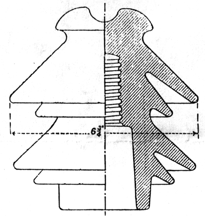 |
| Fig. 11 |
The modification in insulator design, suggested by the experience gained on the Paderno line in Italy, furnishes an interesting study. In Figs. 10, 11, and 12 are shown the three forms of insulator which have been used, all made by Richard-Ginori, of Milan. The first, Fig. 10, was in general form not very far removed from the telegraph insulator. It was made in two pieces, which were fired separately, and afterwards cemented together with a paste of litharge and glycerine. The second and succeeding form, Fig. 11, was found superior in its resistance to surface arcing, as in eighteen months there occurred only two cases in 3500 insulators installed as compared with three cases in 1750 insulators of Fig. 10 pattern. In this Fig. 11 insulator, however, there is more liability to puncture, inasmuch as it is made in one piece, whereas Fig. 10 is made in two pieces. The third and final form of insulator, Fig. 12, represents the result of the experience obtained with the former two, inasmuch as it combines the manufacture in two pieces of the first with the shape of the second. These three forms are all good, but the last is the best. Incidentally, it may be mentioned that Fig. 10 was also installed for the overhead lines of the Milan-Verese Railway, and has proved quite satisfactory.
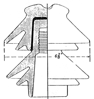 |
| Fig. 12 |
The insulators last described carry lines working at a pressure of about 14,000 volts, but they are capable of carrying pressures much higher. For Paderno they were experimental, but resulting from the experience gained, Fig. 12 is now, as a regular thing, tested by the makers at 90,000 volts and rated for a normal line pressure of 30,000 volts. For the Cauvery Falls Transmission 25,000 insulators were used, made in one piece, and similar in size and shape to Fig. 11. In a year's run with these, at a pressure of 30,000 volts, only eleven were punctured, and one of the failures was reported by the resident Engineer to be due to lightning. From this it is clear that Fig. 12, made in two pieces and thus combining the good points of Figs. 10 and 11, would be quite satisfactory for any working pressure up to 30,000 volts in a climate like that of Lombardy or Mysore.
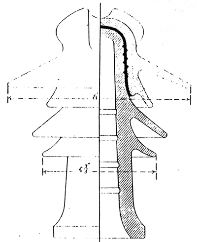 |
| Fig. 13 |
The firm of Richard-Ginori has recently devised an improved form of the Paderno insulator, and has designed a complete series suitable for pressures of from 30,000 to 60,000 volts. The 30,000-volt size is shown in Fig. 13, and it will be observed that the improvements, as compared with Fig. 12, comprise increasing the size of the top dome and giving it more spread, diminishing the size of the underneath petticoats, and providing the lower piece with a tubular stem which completely covers the metal supporting pin. Of the two larger petticoats the upper one has been increased to 8 in. in diameter, while the lower one has been reduced to 5 7/8 in. It will be seen, in fact, that in the step ping down of the petticoats the insulator now approximates in form to the American pattern shown in Fig. 9. These illustrations enable direct comparison to be made between several different makes of insulator employed for a normal working pressure of 30,000 volts. They are the Locke insulator Fig. 9, the Cauvery Falls insulator Fig. 11, the Paderno insulator -- Fig. 12, and the improved Paderno Fig. 13. With the exception of the last, which is not yet actually installed, all have done and are doing good work. But it will not fail to be observed that, as in all electrical equipment, the lines on which evolution proceed converge towards one ultimate form.
