[Trade Journal]
Publication: The Engineer
London, England
p. 404-406, col. 1-3
THE INSULATION OF OVERHEAD LINES.
By W. B. Esson, M. Inst. C. E , M.I. E. E.
No. Ill.
IN the previous articles we dealt with the design of the insulator, but the means by which it is supported from the cross arm is very important. In Europe the practice has been to use invariably a supporting pin of iron or steel, but in America, until quite recently, pins made of wood had always been employed. For the latter, locust wood, oak, eucalyptus, and hickory. have all been put into service, but in the majority of cases locust wood is used as giving the best all round results. Before erection the pins are thoroughly paraffined, or treated with hot linseed oil or asphaltum, which enables them to withstand the action of the weather, and also improves their insulating qualities.
 |
An attempt has been made to standardise the dimensions of wood pins, and in 1903 Mr. Mershon presented to the American Institute of Electrical Engineers a consistent series of designs for pins varying in height from 5in. to 19in., these dimensions being taken from the surface of the cross arm to the extreme top of the pin. It was suggested that the part threaded for the insulator should be 2-1/2in. long for all sizes, and should have a diameter at the point of tin. over the threads, tapering to 1-1/4 in. diameter 2-1/2 in. down. The size of the shank in the cross arm varied from 1-12-in. diameter in the smallest size to 2-1/2in. in the largest, and the depth of the cross arms proposed varied from 4-1/4in. to 5-3/4in. There was a shoulder 3/16 in. all round the shank, so that the diameter of the thickest part was greater than the diameter of the shank. This diameter was continued for 1/4in. above the cross arm, and from this the pin tapered to 1-1/4in., the larger diameter of the screwed top. For pins designed according to these dimensions, experiments showed that there could be applied at right angles to the pin and at the top, a force of from 550 lb. in the smallest, to 750 lb. in the largest, before the fibre began to give way and separate.
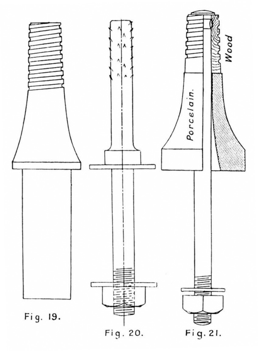
The shape of the pin in general use, and from which Mr. Mershon's designs do not materially differ, is shown in Fig. 19. The threaded portion of the pin is, as a rule, 1in. or 1-3/8in. in diameter, the larger dimension being used for large insulators. For both dimensions the thread is pitched four to the inch, and it is formed by chasing a round groove 1/16 in. deep, so that when finished the thread has a fiat top and a round bottom. There is a taper on the screw of 1/16 in diameter per inch of length, so that the insulator tightens as it is screwed on. The shank has a very slight taper, and is driven tightly into the cross arm, being usually secured in its place by nails.
There is some difference of opinion amongst American engineers as to the relative merits of wood and iron or steel pins for very high voltages. Carefully treated in the way already described, there is no doubt that the wooden pin has considerable insulating properties, but there is great uncertainty as to the period of actual working for which these properties can be relied upon. In use, the pins get dirty, absorb moisture, and become semi-conductors, and the treatment, which at first constituted them good insulators, after a time fails to be effective from this standpoint. That the wood pin has done admirable service in the past must be admitted; nevertheless, most engineers are now discarding it for any pressures above 25,000 volts, and are using iron or steel pins instead. With wooden pins a deal of trouble has been experienced, due to burning, which, of course, will not reappear with metal ones, and though the adoption of a conducting pin necessarily throws an additional electrostatic strain on the insulator, it is better to realise this, and allow for it in the insulator design, than to place reliance on something which may or may not insulate, according to circumstances. The responsibility for the insulation of the line ought to fall wholly on the insulator, and even in cases where wood pins may be used, they should not be relied upon in any sense for insulation.
Metal pins for insulators have been made in cast iron, malleable iron, wrought iron, and mild steel. A pin frequently used is shown in Fig. 20, and consists of a rod On. to lin. diameter, according to the size of the insulator, screwed at its lower end for a nut, and provided with a collar about Sin. from this end, so that the cross-arm may be gripped between the nut and the collar. A thick washer, of ample size, is placed on each side of the cross-arm, and pin, nut, and washers should all be heavily galvanised to protect from the action of the weather. Often the insulator is cemented direct on to the pin, in which case the upper end of the latter, which goes into the insulator, is jagged. For the power lines in Italy the insulators were fixed to the pins in this way, the cement used being composed of ten parts of litharge and one part of glycerine, well mixed. Portland cement or sulphur cement as used in telegraph work will, of course, suit equally well. Iron pipe, drawn down at one end, has been found satisfactory for large pins, and on these the insulators may be cemented in the same way.
An objection has been raised to cementing the insulator on to the pin on the grounds that the pin and insulator combined form an indivisible unit, and that in the case of accident to the insulator the pin must be replaced with it. This is a small matter, and counts for little, as the pins are not wasted. The old insulator parts are simply chipped off them aq opportunity offers, and they are used again as the pins for spare insulators. There is greater mechanical strength with a cemented insulator than with a screwed one, as in the former the pressure between the porcelain and the pin is distributed over all the available surface. In the screwed insulator any slight bending of the pin throws the strain on one particular point, and on this account the insulator is more liable to fracture. When screwed insulators are used with iron pins, it is necessary to provide a cushion between the iron and the porcelain, so that the screw threads in the latter shall not be damaged. This, in the latest construction, takes the form of a lead sleeve cast on the top of the pin, having on its outside a thread to fit the insulator, the softer metal giving the necessary amount of yield.
The composite pin shown in Fig. 21 has been introduced by the Locke Company. It consists of a steel bolt with a snap head, having a locust wood thimble screwed for the insulator at the top and a porcelain base piece underneath. The porcelain base above, and the nut and washer below the cross arm are said to effectually seal the hole in the latter, so that rain cannot get in. This pin is stronger and more durable than the all-wood pin, but inasmuch as at any pressure over 25,000 volts the threaded thimble is liable to be burned to the steel bolt, there is considerable risk attending its use. It is difficult to understand why this burning should occur, but the fact is that it does ; and, moreover, wooden threads seem to have the peculiarity of softening in service, so that in time they crumble into a white powder. As the powder has been found to contain a nitrate salt, the probability is that static discharge inside the insulator is at the root of the matter. But the cure for these troubles is, of course, simple, and is found in discarding wood altogether.
It is thought that the porcelain base piece in Fig. 21 increases the effective arcing distance by causing a discharge to go to the cress arm instead of to the pin. This is no doubt the case in good weather, when the dry surface of the porcelain presents effective resistance, but in rain the base will do little good, as a wet stem of porcelain will carry a discharge with the same ease as an uncovered steel pin. Notwithstanding, a steel bolt with porcelain over it is undoubtedly an improvement on the wood pin, for if in rainy weather arcing does take place to the base, it is not harmed as a wooden pin would be by burning. Whatever kind of pin is used, it is necessary that the insulators be raised well above the cross arms. Arcs between lines have frequently been started by sparks jumping from the lower edge of the insulators to the cross arms when the former were wet or covered with a salt deposit. A safe rule is to maintain between the cross arm and the lowest petticoat a distance equal to the latter's diameter, though where snowstorms are usual this may have to be increased. If the edge of the insulator is too low, it is likely to be reached by snow backing up on the cross arm, and for this reason additional clearance must be provided.
The method of supporting and insulating the conductors where they leave the power-house or enter the transformer-house is another very important matter. No particular method can be described as the best under all circumstances, and the pressure at which the line is worked, the climatic conditions under which the plant is operated, and the size of the conductors have, in each case, to be taken into account. The arrangement must. however, be such that the insulation of the line as a whole is not impaired, while the entrance of rain, dust, snow, or sleet into the buildings must be prevented.
 |
 |
 |
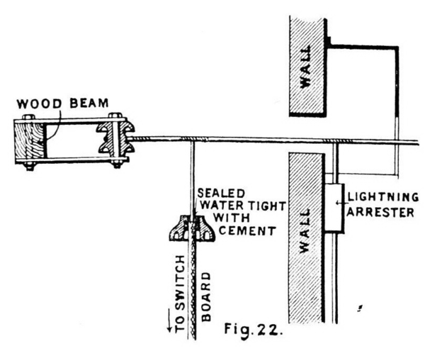
The simplest arrangement is to make an opening in the wall and let the wires pass right through, the openings being of such dimensions that there can be no possibility of the current striking across between the wire and the wall. In Fig. 22 is shown the termination of a 10,000 volt line. The wire is attached inside the generating station to a porcelain strain insulator, carried on shackles, the strain being taken up on a wooden beam. The sketch shows the manner in which the connection is made between the line wire and the switchboard, a porcelain insulating cup being employed to prevent the creeping of moisture from the line wire.
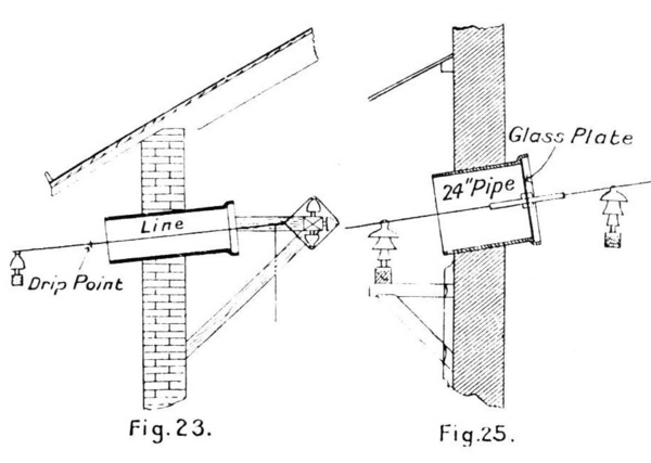
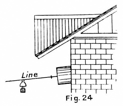
Openings for the wires may be conveniently formed in the walls by building into them earthenware drain pipes, one for each wire. Pipes 12in. diameter serve admirably for pressures up to 15,000 volts. Such an arrangement is shown in Fig. 23, the wire being supported close to each end of the pipe by insulators, thus ensuring its lying in the centre of the opening. A drip point is provided on the wire just outside the pipe to drain water off, and the pipes have an upward slant towards the interior of the house. The projecting roof gives protection and prevents rain from beating in. In a cold country, snow and ice sliding down the roof are liable, with this arrangement, to catch on the wires and pile up between them and the eaves. In such cases it is advisable to put false dormers on the roof, over the wires, in order that ice and snow may slide down clear of them, but, if possible, it should be arranged that the wires enter through a gable and not under eaves. A dormer preventing snow from sliding down on the wires when they pass under eaves is shown in Fig. 24, and when they enter by gable a rain shed on similar lines can be built above the wires.
If the power-house is exposed so that rain and sleet are liable to beat through pipes arranged as in Fig. 23, the inside end should be closed up with a disc of plate glass, thus reducing the opening to the size of the hole in the centre of the glass through which the wire passes. When such a disc is used the diameter of the pipe should be increased to not less than 18in. on account of the liability of the current to flash over the surface of the glass. For pressures above 15,000 volts the wire, where it passes through the glass plate, should be enclosed in an ebony, porcelain, or glass tube with thick sides, extending well on each side of the plate. Such an arrangement with a 24in. length of glass tube is shown in Fig. 25, and is quite effective for pressures up to 30,000 volts. For this latter pressure the pipe is enlarged to 24in., and it is wise to have this diameter for anything over 25,000 volts. In many cases a window built into the wall is substituted for a drain pipe, and into a hole in the glass pane is inserted a tube through which the wire passes. A tube, with a screw-thread cut on its exterior, secured to the glass by nuts of the same material, making a water-tight joint on each side, gives a good construction.
Though the arrangement of 24in. drain pipe and glass plate, or its equivalent window, has on occasion been found satisfactory for pressures as high as 50,000 volts ; generally speaking, when the pressure gets above 30,000 volts a somewhat different arrangement is used. A construction which has given good results in several plants operating at 40,000 volts consists of a window with double or triple panes of glass having insulating bushings or tubes for the wire, placed in holes in the centre of the panes, and joints made tight with cement. A lean-to or screen to keep rain and snow off the glass is employed if the wall through which the wires enter is at all exposed. If frost collects on the glass while the line is shut down, the current at starting discharges over the surface; but this discharge ceases as the frost melts, and appears to do no harm.
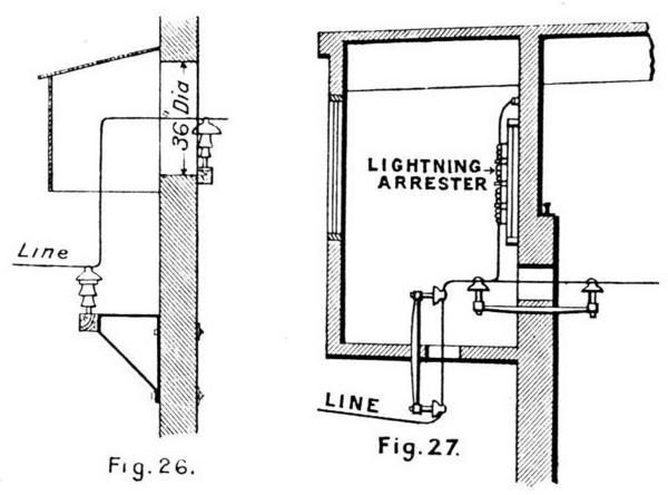 |
A usual arrangement for pressures between 40,000 and 60,000 volts is that shown in Fig. 26. Here a good-sized opening is made in the wall of the power-house, and this is completely protected from the weather by a specially constructed lean-to. Into the opening may be fitted a glass window with a tube for the wire if it is thought that the climate makes this desirable; but in all probability the arrangement shown, which is working successfully at 60,000 volts, would suit this pressure in any climate. The wire is brought up inside he lean-to at right angles to the line, whence, making another right angle, it proceeds inside the building. A modification of the same arrangement is shown in Fig. 27. This has been applied to a concrete steel building where the roof girders are carried beyond the walls of the main building to support a lightning arrester gallery. The result is that the isolation of the arresters in a fire-proof room set apart from the main power-house is combined with a very satisfactory arrangement for the leading-in of the wires. The reliability and simplicity of this construction appear to be all that can be desired. Any water will drip from the wire at the vertical rising through the gallery floor ; the little snow or dust which may blow up through the first opening will not continue on through the second opening into the power-house, and very little cold air can enter the building by way of the gallery.
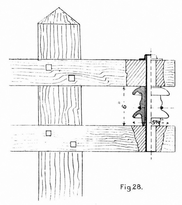 |
It will be obvious that the arrangements last described do not permit of the end strain of the line wires being taken up inside the building, while with all previously I described arrangements this was possible. The strain must accordingly be taken up outside on the last poles, and this is not very easy of accomplishment, especially with heavy lines, if usual line insulators and pins are employed. In a straight pole line the pull of the wire, when the spans are of equal length, is balanced on opposite sides of the supports, and the strain on the insulator is only that due to the weight of the wire and the pressure of the wind. But when the ends of the line arc reached, there is the unbalanced strain to be reckoned with, and to deal with this special insulators have to be designed. Needless to say, a large piece of somewhat fragile material stuck on the end of a long pin, and pulled sideways with a considerable force above the point of attachment, constitutes, from the engineer's point of view, about as bad an arrangement as can be imagined. This is the condition of things when line insulators, as described in the previous article, are employed as strain insulators. Consequently, it is only when no other course is possible that their use for this purpose is justified. To take the strain something more mechanical is needed, and in Fig. 28 is shown the arrangement usually employed. The strain insulator is provided with petticoats, like the insulators previously described, and for exactly the same reasons. This particular insulator is designed for a working pressure of 10,000 volts, and is supported by a pin passing right through it and through cross arms fixed on the pole above and below it. The pin may be of solid iron, galvanised, or of iron pipe, from 1 in. diameter in the smaller sizes to 2in. in the larger, the top being closed by a screwed cap, which also prevents the pin from dropping. A fibre sleeve is inserted between the iron and the porcelain to provide a certain amount of cushioning, and the pin hole is larger at the top and bottom than it is at the middle directly opposite the groove for the wire. The play in the hole ensures that the porcelain will be subject to compression only, even if the pin bends a little owing to the heavy pull. It will be seen that in the case of the strain insulator the load is applied at the middle of a beam supported at each end instead of at the end of a cantilever, as in the line insulator. In the States a straight-grained locust wood pin treated with paraffin frequently takes the place of the iron pipe.
 |
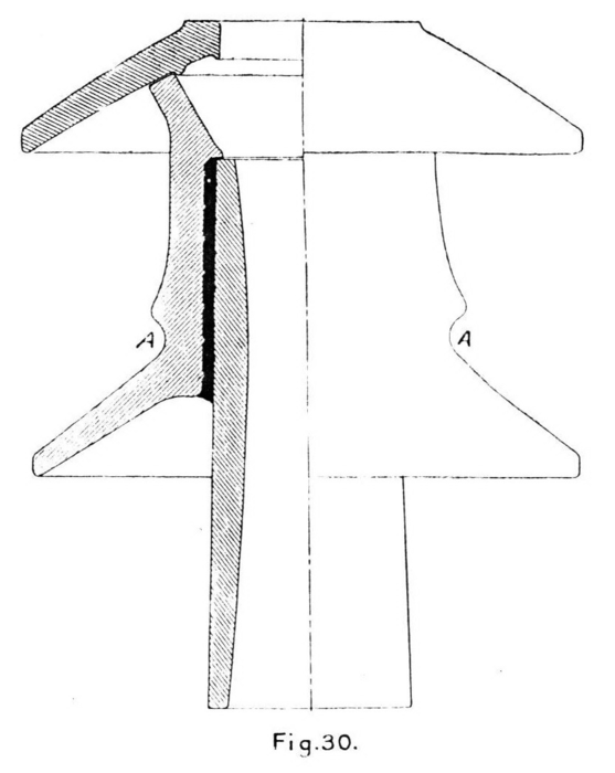 |
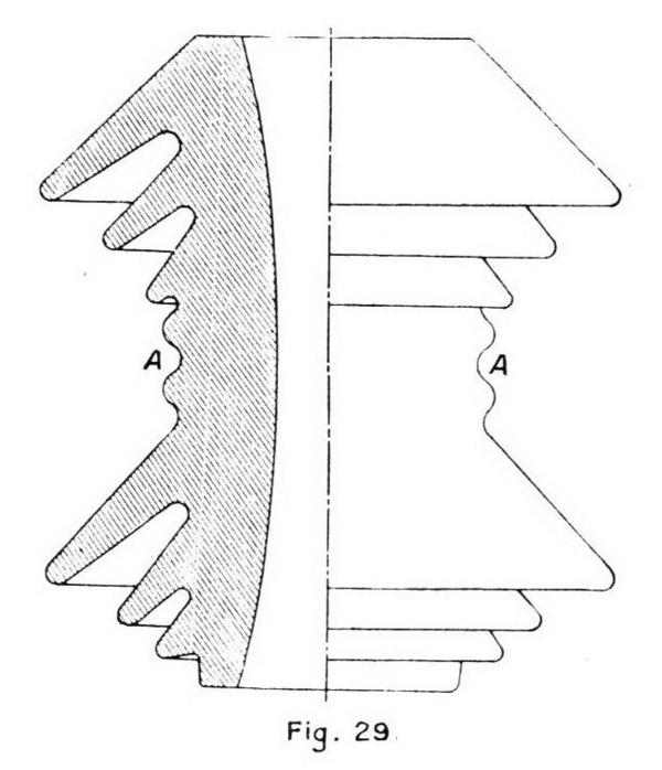
In Figs. 29 and 30 are shown, drawn about quarter full size, two strain insulators intended for a working pressure of 30,000 and 35,000 volts respectively. The former, which is 7-1/2in. diameter and 8-1/2in. high, is a design of Richard-Ginori, and the latter, which is 10-1/2in. diameter and 12-5/8in. high, a design of the Locke Company. While the Italian insulator is made in one piece, the American is made in three, the body and lower petticoat being cemented together, and the top petticoat being loose, with a fitting piece to keep it in place and prevent water from getting on its inner surface. The groove for the wire is marked A in both cases. So far as the author is aware, a strain insulator is not made which can be relied upon to work satisfactorily in the open at pressures higher than the above. No doubt it would be possible to design an insulator for 60,000 volts, but that this would be a somewhat formidable piece becomes evident when we consider that it would have to be the equivalent of two Fig. 18 insulators placed end to end. For such high pressures, where the leading-in arrangement shown in Fig, 26 or Fig. 27 has been adopted, it is consequently usual, notwithstanding mechanical objections, to strain up the wire on line insulators, making the pins specially strong for this purpose.
 |
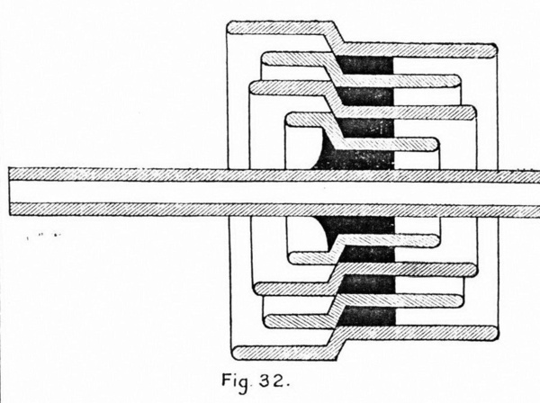 |
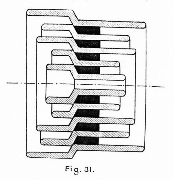
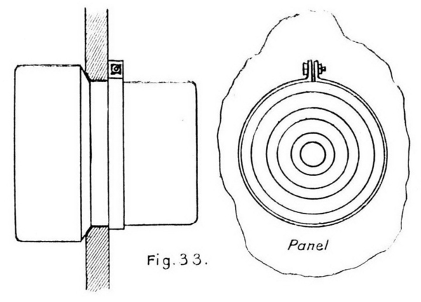
The advantage of taking the end strain of the line inside the building is that, being under cover, ordinary insulators can, for anchoring the wire, be arranged in any desired manner and at any angle without regard to how the insulation is affected by rain or snow, while strain insulators which could only work at 30,000 volts or so outside, do very well for 60,000 inside. The method of taking up the strain shown hi Fig. 23 illustrates the former observation and obviously any arrangement is deserving of consideration which, while ensuring first class insulation at the highest pressure for leading-in enables at the same time the line to be anchored under cover. The Locke Company has recently designed a leading-in insulator which on a dry test has stood pressures far in excess of any yet in use, and in Figs. 31 and 32 are shown two forms of this. It is made of a number of concentric porcelain rings 1/2in. thick, cemented together, and is, from the mechanical point of view thoroughly substantial. The number of rings used varies according to the voltage, the figures showing insulators for a working pressure of 60,000 volts. Fig. 32 is identical with Fig. 31, except that a porcelain tube 24in. long is substituted for the centre piece. The insulator is fixed in a panel, which may be of slate, marble, glass, or seasoned and thoroughly varnished wood, and the diameter of the panel, or its side if square, should be at least twice the diameter of the insulator. In the insulators shown the diameter is 13in. where they fit the panel, and 15-1/8 in. at the larger part. The method of securing to the pane is shown in Fig. 33, the larger diameter being toward the weather.
 |
The insulator shown in Fig. 31 will stand when dry at pressure of 120,000 volts, while the one shown in Fig. 32 which has a porcelain tube substituted for the centre piece, will stand 130,000 volts. When wet the breakdown pressure is greatly reduced, but the design is a decided improvement on the ordinary tube, and there is no reason to believe that it would not give satisfaction at 60,000 volts with a moderate degree of protection. By the latter is meant such protection from very bad weather as is afforded by a dormer, as shown in Fig. 24. This arrangement admits of the line wires passing straight into the power-house, and, assuming it to be satisfactory the necessity for the right-angled arrangement shown in Fig. 26 is done away with. Accordingly, the strain can be taken up under cover on insulators properly designed for the purpose, which gives the best construction. But when so strained the pull should not be allowed to come direct on the wall through which the wires enter. Instances have arisen of trouble through bulging of the walls due to this, and in all cases a proper bracing must be adopted to spread the strain over a large area.
The constructions described by no means exhaust the methods of bringing the line inside buildings, and it will be understood that each installation must be considered with regard to its own particular conditions. Cases exist in which the wires enter the power-house vertically, being strained on trestlework fixed on the roof, and the construction carefully designed, though not generally applicable to the great majority of cases, has given every satisfaction. Again, when the buildings are low, and the wires in the immediate vicinity have to be carried at a considerable height, a special tower may have to be erected, inside of which to terminate the line. The roof must project well in order to protect from the weather, and, in bringing in the wires, is presented the problem discussed in bringing the wires through walls. These towers are frequently cumbersome, if not unsightly, and should only be used when the desired result cannot be accomplished otherwise. In working with high-pressure lines one of the most important things to bear in mind is that there must be no cramping of space. The ideal construction is one which admits of all the line wires being distinctly visible, from the interior apparatus to which they are connected until they are out in the open. To meet this condition plenty of room and wide spacing are essential, and the higher the pressure the greater the need for seeing that the condition is properly met.
* No. II. Appeared October 18th.
