[Trade Journal]
Publication: The Engineer
London, England
p. 351, col. 1-3
THE INSULATION OF OVERHEAD LINES.
By W. B. Esson, M. Inst. C.E , M.I.E E.
No. II.
INSULATORS for pressures above 20,000 volts are generally made in two or more pieces, and for this there are several reasons. It is very difficult to obtain highly fired porcelain in large pieces of intricate shape without flaw, twist, or other blemish, but when the insulator is made up of what amounts to a number of cups and saucers fitting into each other, the process of manufacture, on account of the simplicity of the individual pieces, becomes relatively easy, and the quality of the material is greatly improved from both electrical and mechanical points of view. In order to resist puncture, and for other reasons, a considerable thickness of porcelain is necessary in the head of the insulator, and, because of the improved quality of the material, this is obtained in the most trustworthy manner by having several layers cemented together. Another thing is that when the insulators are made in pieces it is easier to modify the pattern, provided that in designing care has been taken to make the fitting parts of the various pieces interchangeable. Suppose, for example, that the conditions of a projected service demanded that the intermediate petticoat of Fig. 0, page 329 ante, should have more or less spread than shown, while the top dome and lower petticoat did not require alteration. All that would be necessary in such a case would be to use, in assembling the insulator, a middle piece of the form desired instead of one of the form shown, so that by the alteration of only one piece we would get an insulator of the shape wanted. We see, then, that in insulators made of several pieces the quality of the material is superior, the dielectric and mechanical strength are increased, change of shape to meet different conditions is facilitated, while, in addition, the insulator costs less to produce. From the electrical point of view it is not necessary to have insulators up to 40,000 volts in more than two pieces, nor is it necessary to have more than three pieces for any of the higher pressures at present in use. Sometimes the manufacturers will, for convenience, divide some of the pieces in two, firing the divisions separately first, and then uniting them together in the glazing process. It is no uncommon thing to have in one insulator both glazed joints and cemented joints, but the latter should be made, and the insulator built up only after each piece has been separately tested. For making the latter joints neat Portland cement of the consistency of cream run in is as good as anything.
 |
| Fig. 14 |
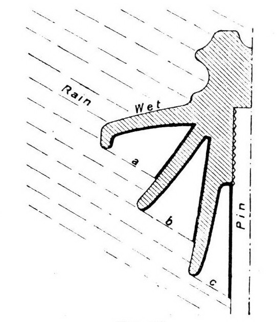
In determining the arcing distance from binding wire to pin across an insulator, it is necessary to bear in mind that in rain certain portions of the insulator will be wet, while other portions will remain dry. In illustrating this point let us fix our attention for a moment on the insulator Fig. 9. When raining the external surface of the dome or' top petticoat will, of course, be wet to its edge, so that for the time being it becomes a conductor, and may be considered as an expansion of the line wire equal to the external surface of the dome. It may be taken that the underneath side of the dome will remain quite dry, as also part of the intermediate petticoat, but how far downwards the dry portion of the latter extends will depend upon the angle at which the rain comes down. If falling vertically there will be no wet other than that on top of the dome, but if driven horizontally and in gusts, a considerable portion of the intermediate petticoat will get a wetting also. Assume that neither condition is present, but that the rain is driven on to the insulator at an angle of 30 deg. We have then the upper portion of the exterior of the intermediate petticoat dry and the lower portion wet, and this also holds with regard to the inner petticoat. The condition of matters is shown in Fig. 14, where the dry surfaces of the insulator are indicated by a thick line, the arcing distance under these conditions being given by the addition of the dimensions a, b, and c. I t has to be understood, of course, that in practice the boundary between wet and dry is, owing to splashing, not nearly so defined as in this diagram. Comparison of Fig. 9 with Fig. 8 shows at once the effect produced by introducing an intermediate petticoat in an insulator with a given size of outer dome and inner petticoat. Due to the spread of the intermediate petticoat the arcing distance in Fig. 9 is increased by 15 per cent.; but the chief point is that the portion of insulator which remains dry is increased by over 50 per cent. Under rain conditions the insulator is not all insulating, but is made up of bands of conducting or wet surface alternating with bands of non-conducting or dry surface, while the spaces measured in straight lines through the air between the edges of the conducting bands all added together constitute the arcing distance.
 |
| Fig. 15 |
 |
| Fig. 16 |
The last sentence suggests considerations as to the conditions under which testing should be done. The general practice of the manufacturer is to test his insulators at from two to two and a-half times the line pressure. In a three-phase system the pressure between wire and ground is only 60 per cent. of the line pressure, so that this gives a factor of safety from 3 to 4, which is ample to ensure that the insulators will not be punctured under working conditions. But it by no means follows that an insulator which will not be punctured will give satisfaction. It is of the greatest importance that the necessary resistance to arcing over the surface be obtained, and while, so far as puncture is concerned, the climate makes no difference, as regards resistance to arcing the weather is the chief factor. It is very seldom that the line insulation breaks down due to puncture, in nearly all cases arcing over the surface is responsible, a circumstance not to be wondered at when we remember that under rain conditions the current will arc over an insulator at approximately one-fourth to one-fifth of the pressure required for puncture. With a view to ascertaining the influence the weather has on the arcing pressure, several experiments have been made, those by Mr. C. E. Skinner in the States being of special interest. Mr. Skinner showed that insulators will, during a moderate rainstorm, or when covered with wet snow, break clown by arcing at about two-thirds of the pressure they will stand when dry and clean. Again, we know that the same pressure will jump, in a fog-laden atmosphere, a 25 per cent. greater space than in a clear atmosphere, and this fact must not be forgotten when deciding upon the insulators to be used. Thus a dry test for arcing is not of much use, and any insulators of a new pattern should be tested under conditions as closely as possible resembling the actual conditions of service. For this purpose arrangements should be made to spray water over the insulator while the pressure is on, in imitation of rain. The water should be projected by a special nozzle at an angle of 30 deg. from the horizontal, producing the effect of wind as well, and should be equal to a downpour of lin. in five minutes, this corresponding to a violent shower. Under these conditions there should be no arcing until the pressure applied between the binding wire and the pin is well over the highest pressure which will ever be reached in actual work. It need scarcely be added that the pressure at which an insulator breaks down depends largely on the shape of the E.M.F. curve of the generator, and tests are only valuable for purposes of comparison when it is certain that in all cases the pressure has followed a sine wave. It is, of course, only necessary to make the spray test on a few insulators of any particular pattern; if these pass the test satisfactorily, it may be taken that all of the bulk standing the puncture test will also be right as regards arcing. Arcing over in the sense above used results from dielectric rupture of the air in the vicinity of the conductor and pin, if the latter is of metal and not of wood. When a certain pressure is reached there is produced a brush discharge, and when this is present it only requires an increase of pressure to cause the discharge and its zone of semi-conducting air to spread so that an arc is started. The brush discharge is due to electrostatic strain, but this can be reduced by careful designing to such an extent that no detrimental effects will result. To ensure this condition it is necessary, for high-pressure work, that there be plenty of material in the head of the insulator, the opposite sides of which have the full working pressure between them, while the shape and disposition of the petticoats must be such as to give minimum electrostatic capacity. This point need not be dwelt upon further, as the illustrations show the designs which have been found satisfactory in practice ; it is well, however, to point out that surface leakage as usually understood is not responsible for the phenomenon referred to, and unless the surface is wet or is covered with salt, soot, or other conducting deposit, the leakage of current is quite negligible. Generally speaking, the pressure at which an insulator will arc over under the worst weather conditions can be determined very nearly by measuring up the arcing distance in the manner already described, and referring the same to a table of sparking distances.
 |
| Fig. 17 |
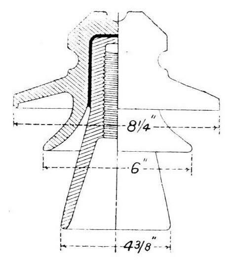
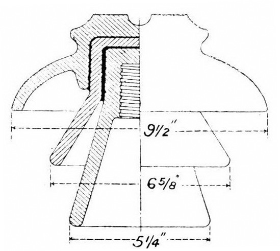
This article would be incomplete without reference to the highest pressures now in use, though it is unlikely that necessity will arise in this country for anything above what has been already referred to. The lower the pressure can be kept consistent with economical transmission the better, and if 20,000 to, 30,000 volts is sufficient for the service, it is manifestly unwise to introduce the risks attendant on the higher pressures of 50,000 or 60,000 volts, and thus sacrifice a certain amount of reliability for the sake, it may be, of only a small saving in copper. It is undoubtedly the case that the higher the pressure the greater the risk, and before running extra risk the loss and gain should be carefully considered. When we come to distances in the vicinity of 130 miles, however, the higher pressures have to be adopted for reasons of economy, and as a consequence there are to-day in the States ten or more systems operating at pressures of over 40,000 volts. Two of these employ pressures between 50,000 and 60,000 volts, while several lines which will ultimately employ the latter pressure are in course of erection. In Fig. 15 is shown an insulator for 40,000 volts, and in Fig. 16, drawn to the same scale, is shown one for 45,000 volts. The former, made in two pieces, is designed by the well-known firm of Schomburg and Son, Berlin the latter, made in three pieces, is by the Locke Insulator Manufacturing Company. The designs present a strong resemblance, and it will be seen that each is provided with only one inter-mediate petticoat. The dome or top petticoats are in these 8-1/4 in. and 9-1/2in. diameter respectively.
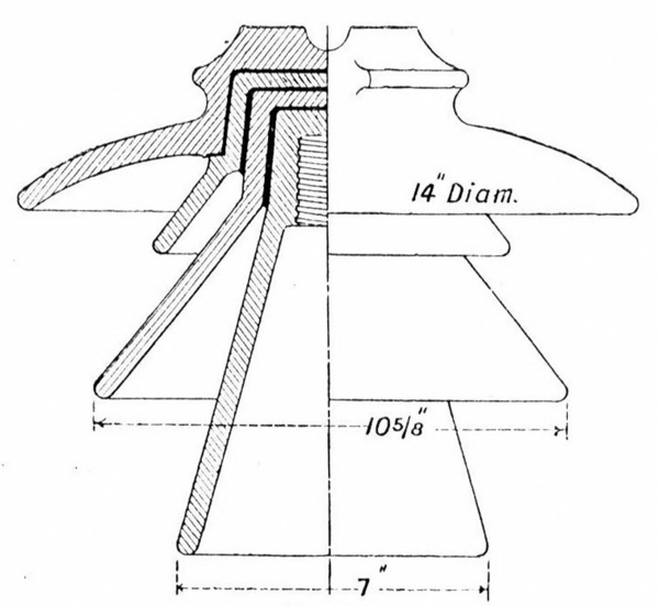 |
| Fig. 18 |
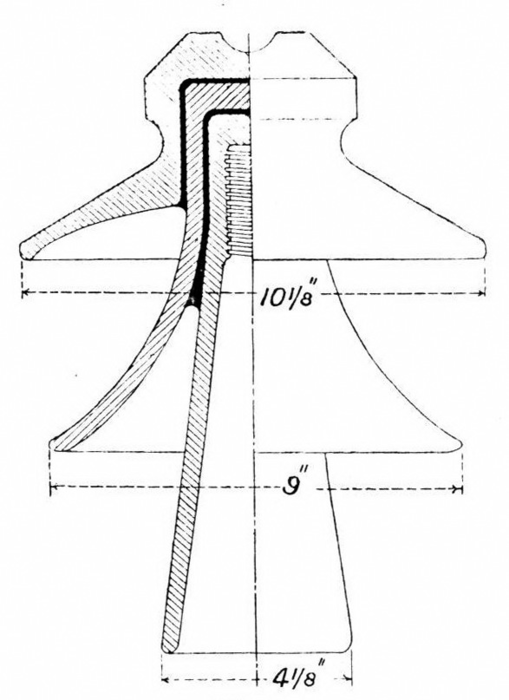
The insulator used for the 50,000-volt Montreal transmission of the Shawinigan Water and Power Company is shown in Fig. 17. This is made in three pieces, and has one intermediate petticoat. The dome is 10-1/8 in. in diameter, while the intermediate petticoat is 9in., the operating pressure being about 53,000 volts. Fig. 18, drawn to the same scale, shows an insulator for 60,000 volts, which is being installed for several important undertakings in America. This is the largest insulator in practical use, and has a dome from l4in. to 14-1/2in. in diameter. Insulators very similar in design have been installed for the 60,000-volt transmission at Guanajuato, in Mexico, for the transmission of the Washington Power Company, now working at 40,000 volts, but which will be ultimately operated at 60,C00 volts; and for the 60,000-volt transmission of the California Gas and Electric Corporation. These insulators weigh from 20 lb. to 25 lb. each, while the insulator shown in Fig. 17 weighs about 131b. Richard-Ginori, of Milan, have also designed an insulator for 60,000 volts, the largest of the series on the lines of Fig. 13. The insulator referred to is nearly a scale enlargement of Fig. 13, the dome being increased from 8in. to 12-1/2in. in diameter, and the length from 8-5/8in. to 15-1/2in. But no insulators of this series have yet been set to work.
The insulators just described represent the climax of design so far, and it remains for the future to show how much farther we shall go. The largest power scheme in process of fulfilment is making preparations for apparatus to work at 80,000 volts, the distance to which the power may be eventually transmitted being considered outside the range of economical transmission, if the pressure is less. But as regards line installation, the work must of necessity be experimental, since no pressures above 60,000 volts have as yet had practical trial.
* No. 1 appeared October 6th
