[Trade Journal]
Publication: Electrical World
New York, NY, United States
vol. 54, no. 18, p. 1037-1040, col. 1-2
The Transmission of Electrical Energy in Southern California.
IN the distribution of electrical energy in Los Angeles three companies are interested, namely, the Los Angeles Gas & Electric Company, the Pacific Light & Power Company and the Southern California Edison Company. The first-named company obtains its energy exclusively from steam, while the other two depend largely on water for their source of supply. Thus the transmission of electrical energy to Los Angeles, and also throughout a large part of southern California, is controlled by the Pacific Light & Power Company and the Southern California Edison Company. The present article gives an outline of the generating apparatus and transmission systems of these two companies.
THE PACIFIC LIGHT & POWER COMPANY.
The Pacific Light & Power Company owns and controls five hydroelectric and three steam generating stations. The principal hydroelectric station is located at Borel, Kern County, Cal., its energy being derived from the Kern River. The station equipment consists of five 2000-kw, three-phase, 2200-volt, revolving-field generators directly connected to turbines operated under an effective head of 246 ft. The generators are operated on the unit system, the e.m.f. of each being raised to 66,000 volts through a bank of three 750-kw, General Electric, oil-insulated, water-cooled transformers. The energy generated at this station is transmitted to Los Angeles over two independent pole lines each equipped with three No. 3-0 copper wires. The distance between the generating station and the receiving station is 127 miles. As indicated on the map, shown in Fig. l, four switching stations are installed on the line at Indian, Oak, Lake and Newhall, situated, respectively, 25, 44, 71 and 96 miles from the generating station. An idea of the arrangement of the switches and the change-overs that can be made by means of them will be gained from Fig. 2. The receiving station in Los Angeles is equipped with four transformer banks, each of which consists of three 750-kw, oil-insulated, water-cooled General Electric units designed to decrease the e.m.f. from 66,000 volts to 15,000 volts to feed into the companys high-voltage distributing circuits.
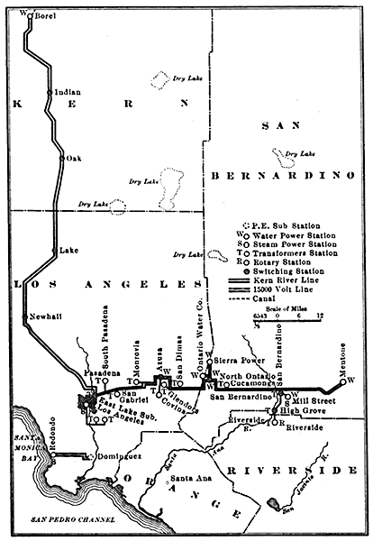 |
| Fig. I.Map of Transmission System of Pacific Light & Power Company. |
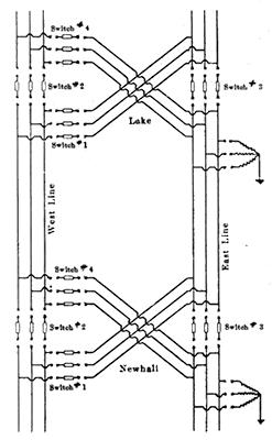 |
| Fig. 2 -- Wiring Diagram of Switch Stations. |
A single-unit hydroelectric plant operating at constant load is located at Mentone, Cal., on the Santa Ana River, about 65 miles east of Los Angeles. This plant contains one 1500-kw, 2200-volt, two-phase, 50-cycle Westinghouse generator directly connected to a Doble waterwheel operating under an effective head of 352 ft. The water is conveyed to the plant through a 36-in. wood-stave pipe line 3.5 miles in length. The load is kept constant on the machine, use being made of a deflecting nozzle in order not to disturb the flow of water, which is used for irrigation. The e.m.f. is raised to 17,500 volts by two water-cooled Stanley transformers T-connected to deliver three-phase energy.
A second station, deriving its energy from the Santa Ana River, is located at Riverside, about 55 miles from Los Angeles. It is equipped with two 300-kw General Electric, 11,000-volt, three-phase, 50-cycle generators directly connected to Stillwell Bierce turbines operating under an effective head of 85 ft. The e.m.f. is raised to 17,500 volts by means of three 200-kw Stanley oil-insulated, water-cooled transformers.
The smallest hydroelectric station of the company is one equipped with two 300-kw Westinghouse, 50-cycle, 500-volt, two-phase generators directly connected to Pelton impulse waterwheels operating under a head of 590 ft. Two banks of Westinghouse oil-filled, water-cooled transformers serve for increasing the e.m.f. to 17,500 volts, three-phase.
A station at Azusa contains five 500-volt, two-phase, 50-cycle Westinghouse generators directly connected to Doble waterwheels operating under an effective head of 396 ft. Five banks of Westinghouse transformers increase the e.m.f. to 17,500 volts, three-phase.
In the Third Street steam station there are one 300-kw Westinghouse, 2400-volt, two-phase, 60-cycle generator belted to a Hamilton-Corliss non-condensing engine; one 750-kw, 2400-volt Westinghouse, two-phase generator directly connected to a cross-compound McIntosh & Seymour condensing engine, and one 1500-Bullock generator of the same type directly connected to a similar engine. These generators supply energy to the high-tension distributing system through three banks of Westinghouse transformers, each consisting of two 625-kw units arranged for converting to 15,000 volts, three-phase. This station is used for relay purposes, the above-mentioned transformers acting as step-down units whenever the steam-generating station is not operating. This station also contains two 225-kw, one 250-kw and two 400-kw rotary converters.
A steam station at Sixth Street and Central Avenue, Los Angeles, is equipped with three Bullock and two Stanley 1500- kw, 50-cycle, 2300-volt generators, four of which are directly connected to McIntosh & Seymour cross-compound condensing engines, the fifth being directly connected to a Nordburg cross-compound condensing engine. The station also contains one 1050-kw Westinghouse, 550-volt, direct-current generator directly connected to a McIntosh & Seymour cross-compound condensing engine.
The largest and most unique steam station is the one at Redondo, which contains three General Electric 5000-kw, 18,000-volt, 50-cycle, three-phase generators directly connected to McIntosh & Seymour vertical, cross-compound, condensing engines. The energy from this station is fed directly to the high-tension distributing system of the Los Angeles Railway Company and the Pacific Electric Railway Company. In these stations use is made of crude oil as fuel. A fully illustrated description of the Redondo station appeared in our issue for Sept. 12, 1908.
A diagram showing the 15,000-volt distributing circuits of the Pacific Light & Power Company is given in Fig. 3, which gives sonic indication of the nature of the load on the system. In addition to its very large railway load, the company supplies energy to a large number of industrial establishments and to many pumps for irrigation. Moreover, its commercial department furnishes electricity for lamps and motors in the towns of Riverside, San Bernardino, South Pasadena, Azusa, Alhambra, Covina, San Gabriel, Huntington Park, Glendora, Dolgeville, Corona, Hollywood, Arcadia and Los Angeles. The president of the Pacific Light & Power Company is Mr. W. G. Kirchhoff, the general manager Mr. A. C. Balch, and the electrical engineer Mr. E. R. Davis.
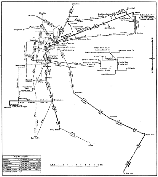 |
| Fig 3 -- Wiring Diagram of 15,000-Volt Connections. |
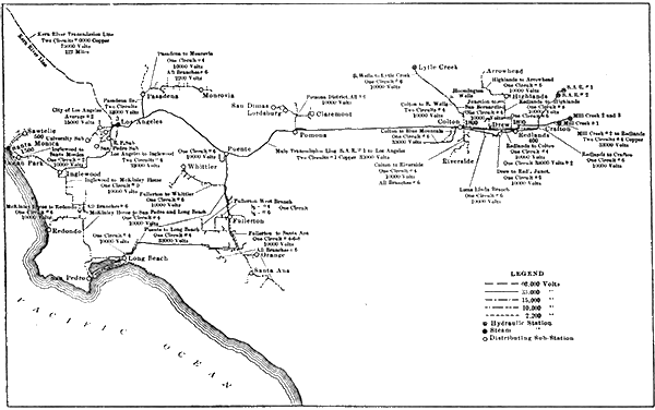 |
| Fig 4 -- Map of Transmission System of the Southern California Edison Company. |
SOUTHERN CALIFORNIA EDISON COMPANY.
A transmission system of more than ordinary interest, on account of the large number of widely separated generating stations that are operated in parallel and by reason of the limitations imposed upon the hydraulic units and the unusual character of the lead, is that of the Southern California Edison Company. This company owns seven hydraulic and four steam stations, the prime movers in which have a total rating of 55.500 hp. Although the distance between two of these stations reaches a value of almost 200 miles, all of the 11 stations are normally operated in parallel. An idea of the character of the load, which will be discussed more fully below, may be obtained from the statement that the distributing circuits extend from the summer mountain resorts to the winter resorts in the lowlands, and cover a territory where artificial irrigation has reached its highest development. Fig. 4 is a map of the transmission and distributing systems, giving the size and voltage of the various circuits and showing the locations of the generating stations and substations. Beginning at the eastern side of the map, the Santa Ana River station No. 1 contains three Pelton and one Doble waterwheel operating under a head of 760 ft., each of which drives a 750- kw, three-phase, 50-cyclc, General Electric generator wound for 750 volts. Four banks of transformers, three of which are of the air-blast type and one oil-cooled, serve for raising the e.m.f. to 33,000 volts. In the Santa Ana River plant No. 2 there are two Doble waterwheels, designed for a 30S-ft. head, driving two 600-kw, General Electric, 750-volt, three-phase generators. Six 175-kw transformers of the air-blast type are used for increasing the e.m.f. to 33,000 volts. These two plants are situated along a stream all of the water of which is used for irrigation. It is necessary, therefore, so to operate the plants as not to interfere even momentarily with the flow of water. In order to obtain this result the waterwheels are provided with deflecting nozzles. However, the plants are operated continuously at such loads as will use all of the water to the best advantage. That is to say, the wheels are run without the governors, which come into play only in case of an excessive decrease in load on the system.
There are three separate hydroelectric developments on Mill Creek, although there are only two generating stations. Development No. 1 utilizes three Pelton wheels under a head of 510 ft. for driving 250-kw General Electric, three-phase alternators designed for 2500 volts. Two banks of Westinghouse water-cooled transformers raise the e.m.f. to the transmission value of 33,000 volts. The generating apparatus for developments Nos. 2 and 3 is placed in a common station building, although two different hydraulic heads are used. Three Doble wheels and one Pelton wheel utilize a fall of 1960 ft. Each of these wheels drives a 750-kw, 750-volt, three-phase alternator, while a fifth Pelton wheel operating at 630 ft. drives a 250-kw generator. The water in Mill Creek is used for irrigation, so that the same restrictions apply to this stream as to Santa Ana River. However, conditions are frequently such that certain of the wheels operate with governors for varying the load without altering the flow of the water.
As intimated above, and as will be noted from Fig. 4, the energy from the Santa Ana and the Mill Creek plants is transmitted at 33,000 volts. What may be called a secondary transmission e.m.f. or a primary distributing e.m.f. of 10,000 volts is used for conveying the energy from the various transformer substations located along the route of the 33,000-volt circuits. One of these substations, which is at Redlands, contains an 1890-kw transformer equipment for the local load and for supplying energy to resorts along the San Bernardino Mountain. A second transformer station is at Colton for supplying energy to the Riverside and San Bernardino neighborhood; it is equipped with 1800 kw in transformers. In the 10,000-volt circuits from the Colton transformer station energy is fed directly from two 250-kw, 10,000-volt generators driven by Pelton wheels receiving the water of Lytle Creek under a head of 483 ft. These machines are usually run at constant load. The Kern River plant was started successfully on Sept 1. Although at the present time the plant on the Kern River is out of service, on account of certain repairs and changes that are being made in the hydraulic tunnels, so that energy is now being transmitted toward rather than from Kern River, yet mention should be made of the normal conditions under which this plant operates. The plant consists of four pairs of Allis Chalmers impulse waterwheels utilizing a head of 874 ft., each of which drives a 5000-kw, 50-cycle, three-phase alternator wound for 2300 volts. There are four banks of transformers for raising the e.m.f. to either 56,000 volts, 66,000 volts or 75,000 volts for transmitting energy 122 miles over a steel-tower line to Los Angeles. Under ordinary service conditions the wheels in the Kern River plant operate under complete control of the governors to carry the fluctuating portion of the load on the whole system. For supplementing the hydroelectric generating equipment outlined above, as may be noted, and for use in emergencies, the company maintains four steam generating stations favorably located along its distributing circuits. The most important steam stations are at Los Angeles and Redlands, while smaller stations are in Santa Monica and Santa Barbara. The Los Angeles station contains two 2000-kw, 2300-volt, Curtis-General Electric steam-turbo units and one 6ooo-kw, 15,000-volt generator of the Westinghouse-Parsons type. Energy is transmitted from this station at 15,000 volts to five substations in the Los Angeles neighborhood, the substations being known as Los Angeles No. 1, Los Angeles No. 2, San Pedro, University and River Power, which are equipped for 1275 kw, 4250 kw, 525 kw, 1200 kw and 750 kw, respectively. The Los Angeles station contains not only the above-mentioned generating apparatus, but it is equipped with transformers for receiving energy at 56,000 volts, 66,000 volts or 75,000 volts from the Kern River plant and 33,000 volts from the Santa Ana, Mill Creek and Lytle Creek plants. Thus its transformer equipment acts as the connecting link between steam and hydroelectric stations rated at 10,000 kw and 29,610 kw, respectively. However, only a part of the power from the generating stations passes through the transformers, which have a total combined rating of only 26,700 kw in 21 units.
A single 450-kw, 2300-volt alternator comprises the generating- equipment of the Redlands steam station. However, the station contains a transformer installation rated at 1890 kw for delivering or receiving energy at 10,000 volts and 33,000 volts. The Santa Monica steam-generating equipment is rated at 200 kw, but the transformer banks, of which there are two, have a combined rating of 1000 kw. The Santa Barbara station contains two 500-kw, 2200-volt alternators and two 500-volt generators, having a total rating of 500 kw.
In addition to the substations mentioned above, there are substations at the following places for receiving energy at 33,000 volts: Pomona, 750 kw; Puente, 450 kw; Fullerton, 2400 kw; Long Beach, 3000 kw; Pasadena, 2550 kw; Inglewood, 2400 kw.
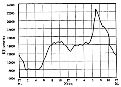 |
| Fig 5 -- Day Load Chart. |
An inspection of the above substation ratings and a study of Fig. I will show the geographical distribution of the load on the whole system. It will be noted that not far distant from the 'Santa Ana and Mill Creek and Lytle Creek stations, with their 9610 kw of generating equipment, there are substations at Redlands and Colton with transformer equipment of 3690 kw for distribution, while along the line to Los Angeles and its branches there are substations at Pomona, Puente, Fullerton, Long Beach and Pasadena, having 9100 kw in transformers. It would seem, therefore, that energy from the two plants along the Santa Ana River, the three plants along Mill Creek and the Lytle Creek plant is seldom transmitted to Los Angeles, but is used for various purposes along the route before reaching that city. Either the Kern River plant or the Los Angeles steam station is capable of supplying all of the power required at the substations in the Los Angeles district. However, when the plants are connected normally in parallel, the operation of the system as a whole is much more satisfactory and reliable than when the separate plants supply energy exclusively to consumers in their immediate neighborhood.
In addition to its lighting loads at the various places mentioned above, and shown on the map in Fig. 4, the company supplies energy to street cars at Redlands, Colton and Riverside and there are connected to its circuits various motors for driving cement mills, rolling mills, ice machines, irrigation pumps, etc. It will be noted that the industrial load is of a very advantageous nature, as viewed by the supply company, on account of both the daily and seasonal load factor. An ideal of the daily load factor can be gained from Fig. 5. The high valley load is attributable to the 24-hour industrial load which forms about one-third of the maximum load and one-half of the average load. The smallness of the seasonal variation in the load will be appreciated at once from the nature of the industrial load. However, it is worthy of note that the railway portion of the load, and even the lighting load, maintains a high seasonal load factor on account of the fact that both winter and summer resorts obtain their supply of electricity from this companys system.
Complete technical descriptions of the Mill Creek, Santa Ana River, Lytle Creek and the steam plants of the company appeared in our issues for Feb. 25, March 4, 11 and 25, and April 8, 1905, while the Kern River installation and transmission system were illustrated and described in our issues for Aug. 10, 17, 24 and 31, 1907.
The president and general manager of the Southern California Edison Company is Mr. John B. Miller. The superintendent is Mr. B. F. Pearson, and the electrical engineer is Mr. J. A. Lighthipe.
