[Trade Journal]
Publication: Western Electrician
Chicago, IL, United States
vol. 42, no. 1, p. 1-5, col. 1-3,1
Power Development on the Chicago Drainage Canal.
THE close of the year 1907 found the initial equipment (16,000 kilowatts) of the power transmission plant on the Chicago Drainage Canal practically completed. The plant consists of a hydro-electric power house at Lockport, Ill, with four 4,000-kilowatt generating units, a 44,000-volt aluminum transmission line about 29½ miles long and a sub-station at Western Avenue and the Canal, in Chicago, where the current is transformed down to 12,000 volts for distribution to local points of use. Sixty-cycle, three-phase current is generated at 6,600 volts and raised in the station to the line potential by large transformers. The whole plant is built to have double the initial capacity, or 32,000 kilowatts, by extensions which can be readily made.
| |||
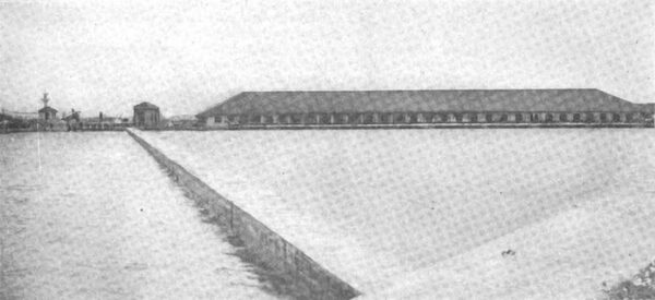
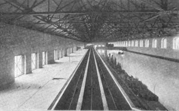
| View From the Upstream Side, Showing Fender Wall. |
| |||
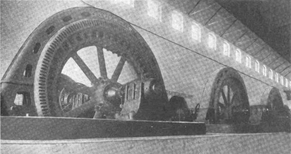
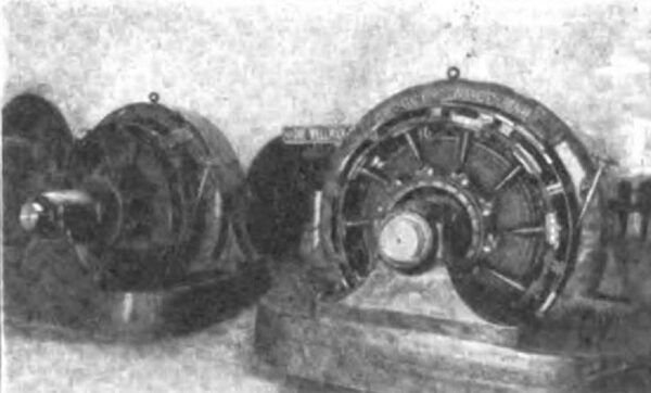
| Three of the Four 4,000-Kilowatt Generators of Initial Equipment. |
| |||
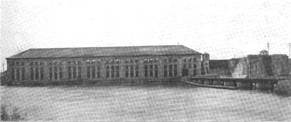
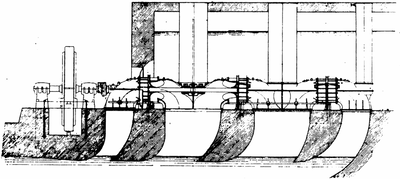
| View From the Downstream Side. Hydro-Electric Power Plant on the Chicago Drainage Canal at Lockport, Ill. |
In every respect the plant is well designed and thoroughly and substantially built. It is owned and operated by the Sanitary District of Chicago, a public body organized under state law and governed by nine trustees, elected by the people. This board built the Chicago Drain age Canal and later the power plant which this artificial waterway affords. About $53,000,000 has been spent on the canal and its appurtenances. Sufficient funds being available to build the plant in first-class shape, no legitimate expense has been spared to secure apparatus and install methods representing the most recent advances in the art of electrical power transmission. The installation is therefore worthy of careful examination as representing the most modern ideas in hydroelectric work in plants of its class.
In the present article a general account of the undertaking will be given, with numerous illustrations. From time to time progress reports of the work have appeared in the Western Electrician, but advantage is now taken of the fact that the initial equipment is complete to view this important enterprise in its entirety.
HISTORICAL AND GENERAL DATA.
In 1889 the Illinois Legislature enacted a law creating the Sanitary District of Chicago, which had for its purpose the building of a canal from the Chicago River to a suitable point on the Desplaines River, the object being to divert the flow of sewage from Lake Michigan, thereby purifying the water supply of Chicago. The work was commenced in the year 1892 and completed in 1900.
The canal extends from Robey Street and the Chicago River to Lockport, Ill., a distance of 29 miles, where it discharges into the Desplaines River, which in turn is an affluent of the Illinois River, which empties into the Mississippi River. At Lockport there is a fall of 12 feet, and the flow of water is regulated by means of a bear-trap dam. With the regulation flow of 275,000 cubic feet of water per minute quite a valuable power was thus incidentally created.
Some agitation was started, as early as 1897, to make use of this power for lighting the streets of Chicago, but the known fact that by extending the channel to a point 134 miles farther down would give a fall of from 34 to 38 feet turned the attention of those interested toward securing the lower site and developing the maximum power. While the city of Chicago was trying to secure the right to develop the power for municipal purposes private interests offered to pay the Sanitary District $5 a year per horsepower and make all necessary improvements to complete the development. A lively discussion of the subject ensued, and the proposal was rejected.
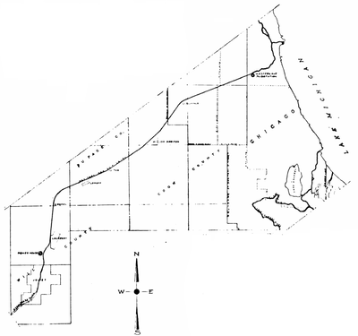 |
| Sketch Map of Chicago Drainage Canal, Showing Location of Power House and Sub-Station. |
The city of Chicago could not raise the necessary money to develop the power, and the Sanitary District did not have the right to do so. The only recourse was to join forces and secure the necessary legislation, which was done in 1903. Some delay ensued pending the collection of the special tax provided, and actual work was not started until 1904, since which time it has progressed without unreasonable delay. The original scope of the work was enlarged to provide for a ship canal as far as the power house and provision made for immense locks to be built at a later date. Canal locks are now provided for locking boats 22 feet wide and 100 feet long from the channel to the tail race, which terminates in the Desplaines River at Joliet, from which point the old Illinois and Michigan Canal is available to the Illinois River.
POWER HOUSE.
Reference to the outline map on next page will show the location of the power house, just outside the confines of the village of Lockport and within three miles of the center of the busy city of Joliet. The power house, controlling works and the ship lock, placed side by side, form the dam across the channel. The power house is 385 feet long, 70 feet wide and 47 feet high. The retaining walls of the channel are 40 feet high and therefore bring the water level near the top of the building on the receiving side, giving a fall of about 34 feet to the turbines, which furnish the power. These turbines are located in chambers at the floor level and discharge through chambers to the tailrace.
 |
| Sectional View of Waterwheel and Generator Unit, Showing Water Levels. |
The movable-crest dam or controlling works joins the power house to the east. This part of the dam is for the purpose of regulating the flow of water in the canal. Ultimately the present controlling works at Lockport will be abandoned.
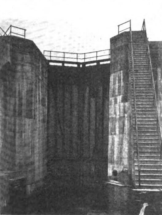
Joining the controlling dam to the east and completing the dam across the channel is the large lock for lowering boats to the lower level of the canal below the power site. The concrete walls of the lock are 52 feet high at the lower end, and the lock is said to be the deepest in existence.
Built at an angle across the channel is a concrete guard or fender protecting the forebay from floating ice. This wall diverts the ice to the controlling dam. Within the forebay and protecting the wheel chambers from drift wood or other material which might get past the ice guard are a series of iron racks extending the length of the power house.
Everything about the plant is built on solid rock, and the various structures are made of concrete. All the stone required in the concrete mixing was obtained on the spot. The power house is fireproof, no combustible material being used in its construction.
GENERATORS AND TRANSFORMERS.
The power house is designed and constructed for the installation of eight generators of 4,000 kilowatts each, and three exciter units of 350 kilowatts each, to be direct-connected to horizontal waterwheel units of 6,000 horsepower each in the case of the generators and of 600 horsepower each for the exciters. The present equipment is four 4,000-kilowatt Crocker-Wheeler three-phase, 60-cycle, alternating-current generators and two 350 kilowatt direct-current exciter units, each driven by waterwheel units built by the Wellman-Seaver Morgan Company in the manner shown by the section drawing. A fifth unit is now being built and will be installed early in the spring.
 |
| Transverse View of Portion of Drainage Canal Power House. |
| |||
| Six 1,333-Kilowatt Transformers in Drainage Canal Power House. |
Rated at 4,000 kilovolt-amperes (60 cycles, 6,600 volts), the generators are operated at 1632 revolutions per minute. They are of very rigid construction, having frames of the box type, strong enough to prevent distortion due to their own weight and magnetic pull. The stator laminations are punched with partly closed slots, permitting the use of solid pole shoes. The windings of the stator are of the threaded conductor type, the conductors being placed in substantial insulating tubes inserted in the slots. This winding is a particularly desirable one, because of the excellent insulation obtainable and because it leaves the rotor windings accessible without shifting the rotor axially. The distance between bearings is short and a rigid shaft is therefore assured. The rotor consists of a solid casting split in two parts and firmly bolted together, on the circumference of which the poles and pole shoes, each a solid forging, are securely bolted. The rotor winding consists of flat copper conductor wound on edge, thus insuring radiating surface to every turn of the winding. This feature, together with the ventilated type of stator core and housing, is believed to insure low and uniform temperatures throughout.
| |||
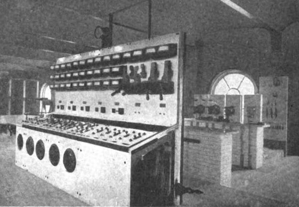
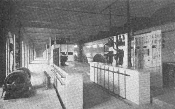
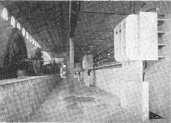
| Transformers on Main Floor, Generator Oil Switches on First Gallery and Outgoing Line Switches and Sectionalizing Switch on Top Gallery. Longitudinal View of Portion of Equipment of Drainage Canal Power House. |
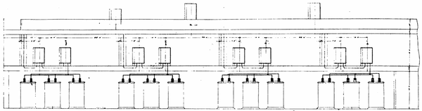
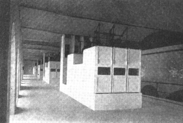
The transformer equipment consists of 12 single phase oil and water-cooled step-up transformers of 1,333 kilowatts each, built by the General Electric Company, which company also furnished the switch boards, high-tension switches and lightning-arrester equipment. The transformers are arranged in banks of three. Each is guaranteed to operate safely under an overload of 25 per cent. The arrangement of coils is such that damaged ones may be easily replaced.
GENERAL ARRANGEMENT.
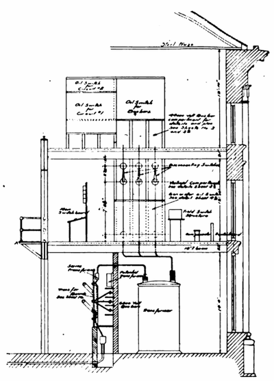
The north half of the power house--a space 385 by 35 feet--is devoted to the generators and exciters, the waterwheel for each machine being located in a chamber adjoining. Traveling over the generator space is a 40-ton electric crane. The south half of the main building contains the switch boards, transformers, bus-bars, oil switches, circuit-breakers, lightning-arrester apparatus, etc. Above the main floor are two galleries as shown in the transverse sectional drawing.
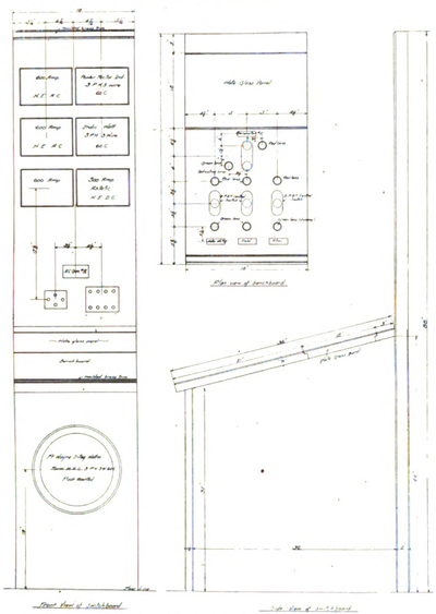 |
| Details of Main Control Switchboard. |
The general arrangement of the station is such that the waterwheel, generator and three transformers constitute a unit and is treated as such to the high-tension bus-bars, all switching being done on the high-tension side of the transformers. Transfer bus-bars are provided for the purpose of making the generators and transformer banks interchangeable, and will only be used in case it is desired to operate a generator on a bank of transformers ordinarily used on another generator. Each transfer board used with the transfer buses consists of a slab of marble 90 inches high, 63 inches wide and two inches thick and provided with barriers. It is provided with three single pole, single-throw, hook-type switches of 450-ampere capacity, 6,600 volts; three single-pole, double-throw, hook-type switches of 450-ampere capacity, 6,600 volts; three connecting bars between jaws of single and double-throw switches. Each alternating-current generator armature is connected to its transfer board by two three-phase stranded-copper cables of 300,000 circular mils each. Three series trans formers are mounted on the top of each transfer panel, and through these the top switches on the board are connected to the primary side of the corresponding bank of main step-up transformers.
SWITCHING APPARATUS AND CURRENT CONTROL.
To insure that a combined unit may be disconnected from the bus-bars under extreme conditions the high-tension leads from the transformers are carried through two three-pole oil circuit-breaker switches placed in series. After passing through these switches, which are placed on the first balcony or gallery, the leads are carried up to the second or top gallery in enameled brick compartments to the high-tension bus-bars, which are en closed in compartments similarly constructed. To these bus-bars, which extend the entire length of the four units, the two outgoing circuits are connected through oil circuit-breaker switches provided with time-limit relays.
The circuits are carried in enameled brick compartments to the end of the building, where they are provided with lightning arresters at the point where they leave the power station.
| |||
| Oil Switches. |
| |||
| Main Control Board in Drainage Canal Power House. |
The exciter units are connected to the bus-bars through automatic circuit-breakers and remote-controlled switches. These bus-bars are placed on a structure built of white enamel brick, arranged to carry the switches. From the bus-bars leads are carried to a similar structure on which are mounted the field switches for the alternators. Provisions are made on these structures for the installation of future apparatus. The rheostats for the fields of the alternators and exciter units are placed on the second gallery and are remote controlled. The total resistance required for each of the alternating current generator field rheostats is 1.6 ohms in 50 divisions; maximum current in fields with all resistances cut out, 150 amperes; minimum current in fields with all resistances cut in, 78 amperes. The resistance contained in the rheostats is pro portioned to regulate the current strength between 78 and 150 amperes in 50 equal steps; the total resistance required for each of the direct-current generator field rheostats being 25 ohms in 100 di visions.
The control board is located on the first gallery and is built in uniform panels--one for each generator and exciter unit. The exciter panels are provided with the usual instruments, and each alternator panel has an ammeter on each phase, a watt indicator, power-factor indicator, ammeter for fields, synchronizing and voltmeter receptacles. A swinging panel contains two 6,600-volt voltmeters, frequency indicator and voltmeter on exciter bus bars. A synchroscope is placed in the center of the board.
| |||
| This Lock, With Lift of 52 Feet, is Perhaps the Deepest in the World. Navigation Lock at Lockport Power House on Drainage Canal. |
| |||
| Two 350-Kilowatt Exciters in Drainage Canal Power House. |
All indicating instruments are practically dead beat and are guaranteed to be accurate within one half of one per cent. throughout their entire range. The finish is a dead black with polished brass trimmings lacquered to prevent tarnishing. The direct-current instruments are of the shunt type and conform in size and appearance with the alternating-current instruments. The alternating-current instruments are used on 6,600-volt current. The operating panel is provided with push and pull type of switches for operating all switches, rheostats and waterwheel governors. Each switch is provided with lamps to indicate the movements of the device it controls. An integrating wattmeter is also provided for each alternating-current generator. The board is so condensed that the entire plant may be operated in the limited space of eight feet. Simple in appearance, the plant has yet apparently all the required flexibility.
PROTECTION AGAINST ICE.
Particular attention has been given to a source of trouble usually experienced with waterpower plants, during winter months-that is, anchor ice and floating ice. A diagonal fender wall with arches four feet below the surface has been constructed in front of the wheel pits, and the greater part of the troublesome ice will be di verted to a bear-trap dam discharging below the power house. Such ice and debris that may reach the racks in front of the wheel pits may be raked out and passed over another and smaller dam which discharges below the power house. These provisions insure freedom from any actual interference in operation.
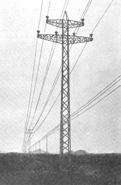
TRANSMISSION LINE.
With its 60-foot steel masts and two circuits of three aluminum wires each, the transmission line running from the Lockport power house along the Drainage Canal to the sub-station at Western Avenue and Thirty-first Street, Chicago, is a fine piece of work. The wires of each three-phase circuit (one is held in reserve) are arranged in delta shape, as shown in an accompanying picture, one circuit on each side of the mast. The wires are spaced six feet apart. As stated, the transmission potential is 44,000 volts. A ground wire is carried on the peaks of the poles.
| |||
| Low-Tension Busbar Structures in Drainage Canal Power House. |
| |||
| View Showing Busbars and Circuit Compartments in Top Gallery. |
| |||
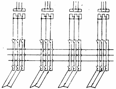
| Transfer Board and Busbars. |
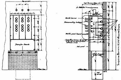 |
| Details of Transfer Board and 6,600 Volt Busbars. |
The poles or masts are of steel, square in plan section, of bridge construction, and weigh complete 4,000 pounds. On a side they measure 42 inches at the base and 20 inches at the top. The two cross arms are similarly of bridge construction, the lower arm being 18 feet long and weighing 600 pounds, while the top arm is 12 feet long and weighs 300 pounds. The material used in the diagonal braces is 2 by 2 by 3-16-inch angle steel. The size of the material in the corner posts varies from 3½ by 32 by 4 inch at the base to 3 by 3 by 3-16 inch at the top of the pole. The rivets in the body of the pole are all three-quarters inch and in the cross-arms five-eighths inch. The Aermotor Company made these masts and received $130 apiece for the number furnished, between four and five hundred.
The poles are placed 350 feet apart. They are set into the ground six feet and the hole filled in with concrete, which is brought up six inches above the surrounding earth and rounded off at the edges so that no water will lodge about the base. The accurate alignment is beautiful and praiseworthy. The poles are designed to carry the transmission wires on the lower arms 47 feet above the ground.
| |||
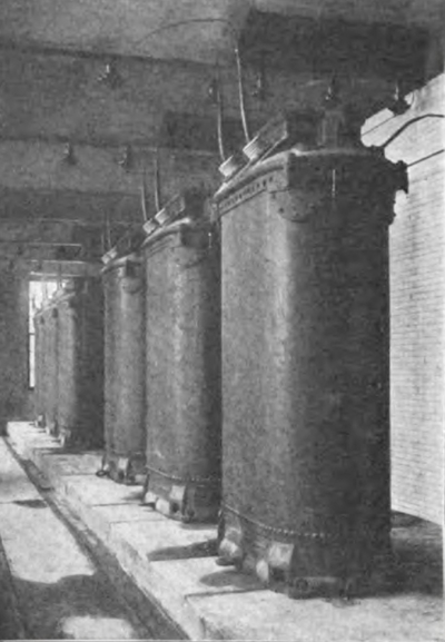
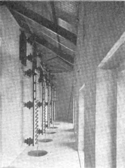
| Lightning Arresters in Drainage Canal Power House. |
The wires are carried 16 inches above the metal arms. The Locke insulators used have a diameter of 14 inches and are 12 inches high. They were tested assembled ready for use at 120,000 volts. Each of the four shells or petticoats tested at 60,000 volts before assembly. This insulator, mounted on a suitable metal pin, is guaranteed for a maximum horizontal strain of 4,000 to 5,000 pounds and is ordinarily rated for 60,000 volts. At the top of the pole the four corner posts end in a cap which is fitted with a socketed clamp tightened down on the one-half-inch iron ground wire, carried the whole length of the line. This cable will connect all the poles electrically, and on account of its position above the transmission wires is expected to receive any lightning which may strike the line and carry it off to the excellent grounds afforded by the concrete-imbedded poles. The construction as described has proven entirely satisfactory, and no line trouble has appeared in five weeks of operation.
SUB-STATION.
In the sub-station each line terminates in a set of bus-bars, to which are connected, through oil circuit-breaker switches, two banks of step-down transformers. These transformers may be operated in parallel by means of an oil switch between the two sets of bus-bars. The secondary current passes through similar oil switches to a set of low tension bus-bars arranged exactly the same as the primary side for parallel operation. From the low-tension bus-bars the distributing circuits pass through oil switches to points of distribution. Each circuit is to be equipped with a total watt indicator, power-factor indicator and integrating wattmeter.
 |
| Transfer Board and Transformer Connections. |
| |||
| A View of the Drainage Canal Power-Transmission Line From Lockport, Ill., to Chicago. |
The control board in the sub-station is a duplicate of the panels on the power-station board, and the switching arrangements are identical. A motor generator unit has been provided to supply direct current for operating switches and lighting the building, and a 1,000-ampere-hour storage battery, to be used in case of emergency, is provided. Motor-driven centrifugal pumps in duplicate are installed for the purpose of supplying cooling water to the transformers.
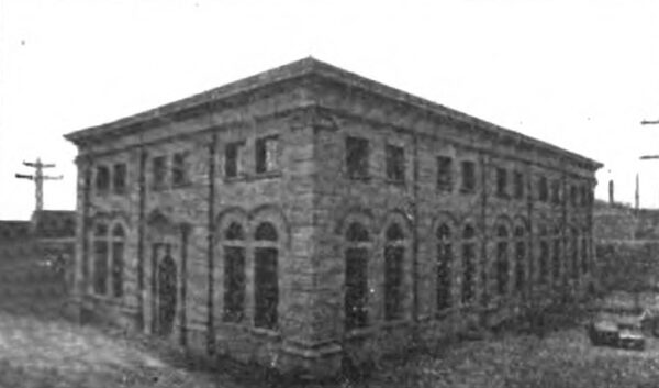
The sub-station building is an attractive yet dignified structure of concrete. It is 124 feet long, 70 feet wide and 42 feet high.
APPLICATIONS OF THE CURRENT.
The city of Chicago will be among the first users of the current available by the Drainage Canal power development, having contracted to take 7,000 kilowatts. For some time the city electrical department has been busy installing the distributing system from the sub-station, and City Electrician Carroll is now preparing the city lighting plants for the Lockport power. One new transformer station has been built by the city, and in the existing street-lighting plants electric motors will take the place of the steam engines for driving the generators.
| |||
| Western Avenue Sub-Station, Chicago Drainage Canal. |
Preparations are being made by the Sanitary District to do the pumping for the proposed North Channel by screw pumps driven by slow-speed 450 horsepower motors installed at Wilmette and taking current from the Western Avenue sub-station. Others who will use a considerable amount of the Canal power are the West Park Board, the township of Cicero and the village of Morgan Park. The Sanitary District will receive $15 a horsepower for the current.
PERSONNEL.
Mr. Robert R. McCormick is president of the board of trustees of the Sanitary District of Chicago. Mr. George M. Wisner is chief engineer. The trustees have expended about $4,000,000 on the power development of the Drainage Canal since work was begun in 1904. The electrical plant has been installed under the supervision of Mr. Ed ward B. Ellicott, electrical engineer for the Sanitary District. Mr. Ellicott has brought to this task the comprehensive resource, the unflagging zeal and the excellent technical ability which have characterized all his work, whether as constructing engineer for a great electrical company, city electrician of Chicago, or chief electrician and mechanical engineer of the St. Louis Exposition. The power station is in charge of Mr. W. C. Robinson.
