[Trade Journal]
Publication: American Electrician
New York, NY, United States
vol. 17, no. 1, p. 32, col. 1
New Apparatus
and Appliances.
·
·
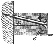
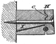
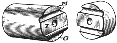
Wiring Cleat. — The cleat or [missing text] from an insulator knob [missing text] electric wires is familiar to those interested in such matters. Fig. 5 illustrates a new form of this type of knob which has been patented by Mr. E. C. Hunt, of Belle Plaine, Iowa. The insulator comprises a knob and a cap, both grooved on their abutting faces to receive the wire and also provided with a groove in the knob and a corresponding ridge on the cap to serve as a sort of pivot and ficilitate [sic] facilitate the clamping of the wire when a screw is set through the hole in the center into the material upon which the knob is mounted. The principal feature, however, is the shape of the central hole through the knob portion; the hole is round at the clamping face, but widens progressively into an oblong section at the back end, as shown at l in Fig. 3; the object of this is to allow the screw to be set at an angle, as shown here, whenever that may be necessitated by local conditions. The force of the knob from the fulcrum ridge, C, to the extreme edge is slanted, as indicated at H, Fig. 4, in order to give room for the tilting of the cap when a larger wire is clamped in the wire groove. This is shown in Fig. 4, which also shows the retaining screw set in straight, as it would be under ordinary conditions. Patent No. 776,514.
 |
| Fig. 3. |
 |
| Fig. 4. |
 |
| Fig. 5. — Wiring Cleat. |
·
·
