[Trade Journal]
Publication: Electrical World
New York, NY, United States
vol. 28, no. 24, p. 717-720, col. 1-2
Niagara Power Transmission Up to Date. IV.
BY FRANK C. PERKINS.
CURRENT FOR THE PITTSBURG REDUCTION COMPANY.
THE original installation of rotary and static transformers for the Pittsburg Reduction Company for the purpose of producing the metal aluminum consisted of four rotary and eight static transformers. These machines received their current from the Niagara Falls Power Company. The illustration shows the four 500-hp rotary transformers and eight 250-hp static transformers as originally installed. Since the first installation was completed, a fifth rotary and two additional static transformers have been added, with additional space provided for three more 500-hp rotaries and six more static transformers. The current is a two-phase alternating current which is conducted to the transformer house through an underground subway large enough fora person to walk through. It extends from the man-hole opposite the aluminum works to the transformer house of the Niagara Falls Power Company.
| |||
| Fig. 1.First Installation of Pittsburg Reduction CompanyFour Rotary Transformers, 115 Volts -- Alternating to 160 VoltsDirect Current. Two-Static Transformers, 2000 115 VoltsInsulating Porcelain Tubes. |
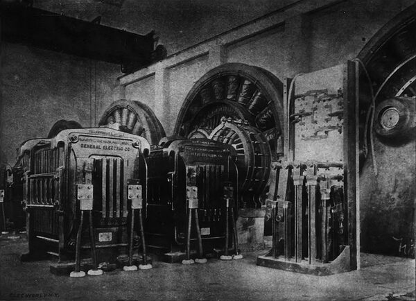
The transformer room is 87 feet long and 50 feet wide and the cables and conductors are all carried underneath the floor. The last rotary transformer installed may be seen in the illustration as well as the switchboards for both the alternating and direct current distribution. The capacity is 600 kilowatts at 160 volts, the speed is 188 r. p. m., and a current of 3700 amperes is delivered to the bus bars. From the subway the current is received as a two-phase alternating current at 2200 volts, is then transformed to allow voltage and conducted to the rotary transformers, where it is changed from a two-phase alternating current to a continuous current of about 160 volts, which is best adapted to the production of aluminum. The capacity of the direct cables is enormous, as very heavy currents are used in the process. The carbon lined pots are arranged in series and connected to the electrical terminals. Copper rods are connected to the main line and then attached to heavy carbon cylinders or rods which act as anodes; the pots themselves with their lining are connected to the other side of the line, the current depositing the aluminum upon the bottoms of the bowl or pots, which act as cathodes. The metal is dipped out of the pots daily, and in its place is added more of the mixture to be reduced. The alumina is dissolved in a bath of molten fluoride of aluminum and fluoride of calcium or fluoride of sodium.
The operation is a continuous one, and the current is used day and night for months and months without interruption except by accident, or replacing pots which, however, last a considerable length of time. Each pot requires from four to six volts, so that a large number may be connected in series upon a 160 or 280 volt circuit.
| |||
| Fig. 2.8000-Ampere Copper Bus Bars. 250 3/8-Inch Aluminum Conductors in Distance. |
| |||
| Fig. 3.Aluminum Conductors and One of the 560-Kw, 280-Volt Generators. |
The high-tension cables are lead-covered, and are 1.75 inches in diameter, outside measure. Each cable has a cross-section of 950,000 circular mils. The main cables are laid in a subway. Connected to these cables are four sets of cables, two in multiple, lead-covered and 32 inch in diameter made up of strands of No. 17 wire. These cables are connected to the static transformers by the switchboard shown in the illustration. The static transformers reduce the 2200-volt current to 115 volts and after passing through the rotary transformers the 160-volt direct current is delivered to the bus bars through the switch board shown in the illustration. The bus bars, it will be noted, are very heavy and are of copper. In the new plant the bus bars in the aluminum works and conductors leading to them are of aluminum.
The cables connecting the low-tension secondary of the static transformers to the lower part of the alternating switchboard are of 1,500,000 circular mils cross-section. It is necessary to maintain a blast of air through the static transformers in order to dissipate the heat, and this is done by means of the centrifugal blowers operated by electric motors seen in illustration. The efficiency of the static transformers is very high, being 98 per cent.
The enormous demand created for aluminum has made it necessary for the company to increase its capacity for turning out the metal. The new works just completed and now in operation 1s located on the property of the Niagara Falls Power Company, on top of the high bank of the Niagara River below the Falls. The new building is very large, covering two acres of land and gives employment to a large force of men, both day and night. This plant is now in perfect operation and plans have been made for doubling its present capacity. In the power-house is now installed 4500 horse-power, available in dynamos of which they are now using 3000 horse-power. This s all direct-current machinery and the power is transmitted to the plant where it is used in the form in which it is generated. In this respect this plant differs from others using the power of the Niagara Falls Power Company, where the current is received in the form of a high-potential direct current. The aluminum conductors in the power house which convey the current to the reduction plant on the top of the bank each consist of bundles of 250 three-eighths inch aluminum rods. The weight of aluminum required for this purpose is little less than half that of copper rods of an equivalent carrying capacity. Recent experiments have shown that ordinary commercially pure aluminum has from 64 to 65 per cent. of the conductivity of copper and, very pure grades of aluminum are said to run as high as 70 per cent.
| |||
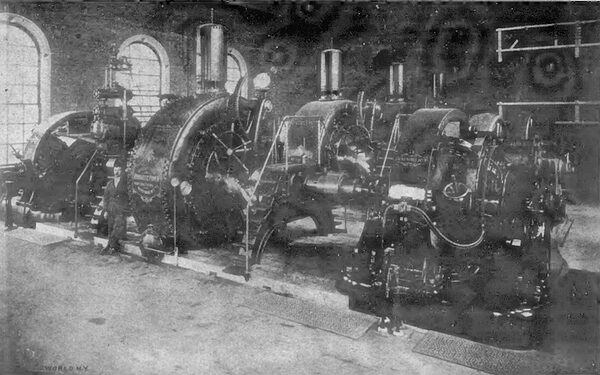
| Fig. 4.New Power Plant of the Niagara Falls Hydraulic Power & Manufacturing Company, Showing Turbines, Governor and Street Railway Generators. |
At the present price at which aluminum is sold in large quantities it is just about equivalent to copper for the purpose of electrical conductors. The conducting line in-the upper plant is built of bars 12 inches deep and 1 inch thick.
It has been found by experience with the old plant where aluminum conductors have been used for several months that it answers equally as well as copper. The joints, of which there are a number in the line, do not heat and the line gives no trouble in any way.
The output with the new plant together with plant already in use will be about 10,000 pounds of aluminum per day and this amount can readily be increased from machinery already in place. The output per day will seem enormous when it is known that the total output of aluminum in the United States for the six years from 1883 to 1888 was only about 40,000 pounds or four days product of the present works. In 1883 only 83 pounds were produced; 1884, 150 pounds; 1885, 263 pounds; 1886, 3000 pounds; 1887, 18,000 pounds; 1888. 19,000 pounds. The present plant will produce at the rate given by Mr. Hall 3,650,000 pounds per year or 10 times the amount produced in the United States in 1893 and seven times the total product of the United States in 1894, which was 550,000 pounds.
The two bundles of aluminum conductors mentioned above may be seen in one of the accompanying illustrations with their connections to the main copper bus bars in the power house of the Niagara Falls Hydraulic Power & Manufacturing Company.
The current for the Pittsburg Reduction Company in the new works is supplied from Westinghouse Electric & Manufacturing Companys generators, shown in illustration. There are in all six eight-pole generators delivering a direct current to the bus bars at 280 volts. The six machines may run in parallel, delivering 2000 amperes each at 280 volts. The two Westinghouse machines, having a capacity of 750 horse-power, or 560 kilowatts, are directly connected by flexible spring: couplings to a Leffel water turbine generating 2000 horse-power.
| |||
| New Apparatus of the Pittsburg Reduction Company. Fig. 5 Direct-Current Side of Rotary Transformer. 600 Kw. 188 Rvs. 160 Volts. Fig. 6. High Tension Alternating Current Switchboard. Fig. 7. Blowers for Cooling 2000-Volt Static Transformers. Fig. 8 Two-Phase Alternating Side of Rotary Transfomer. Fig. 9. Direct-Current Switchboard and Bus Bar for Latest Rotary Transformers. |
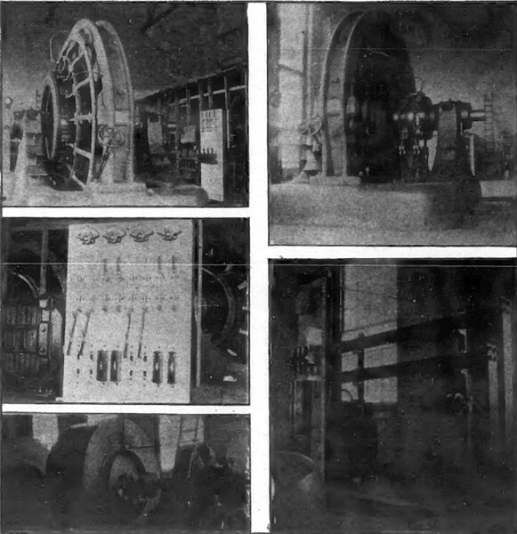
There are three Leffel wheels so connected generating electric power for the aluminum works. The copper bus-bars shown in illustration are 10 inches high and 3/4 inch thick, and to each of these bus-bars are attached the 250 aluminum wires No. 00, which are painted with black insulating paint and carried through wooden conduits up to the aluminum works, as shown in illustration. Six Weston ammeters indicate the current flowing, each reading to 2500 amperes. These instruments are all of the type having illuminated dials, and a single Weston voltmeter is used, indicating as high as 600 volts. The Pittsburg Reduction Company also has a plant in operation at New Kensington, Pa., which is operated by steam power.
This plant is a model steam plant, and is using coal costing 60 to 70 cents per ton delivered to the works. Thus, Niagara power is considered cheaper than steam power under the most favorable circumstances.
THE NIAGARA FALLS HYDRAULIC POWER & MANUFACTURING COMPANYS NEW PLANT.
The Niagara Falls Hydraulic Power & Manufacturing Company, the rival of the Niagara Falls Power Company, is now ready to furnish 40,000 horse-power.
The opening of the rival companys plant was witnessed by the most prominent citizens of Niagara Falls and Buffalo. The party from Buffalo went to the Falls on the new and superb drawing room car now in use on the Buffalo & Niagara Falls Electric Railway. The company is now furnishing over 8000 horse-power. The enlargement of the hydraulic canal, cut through solid rock, has been completed and 40,000 horse-power under a head of from 100 to 200 feet is available for use, and it is believed that this power will be constant and reliable in every way. The writers attention was called to the latest development of using power under a head of 210 feet.
The company is at present furnishing current for the Lewiston & Youngstown Electric Railway, the Pittsburg Reduction Company, and Niagara Falls & Lewiston Electric Road, known as the Great Gorge Road, and several mills and factories.
The Gorge Road is equipped with cars of the J. G. Brill Company and has a very fine equipment throughout. Capt. J. M Brinker, of Buffalo, is president, and J. K. Brooks, superintendent. The Gorge Road was constructed with great difficulty and gives a most excellent view of the Falls and Whirlpool Rapids. The grades on this road are quite heavy. From the cantilever bridge there is a 5 per cent. grade for several hundred feet, then for about a halt a mile the grade drops to 4 per cent., then for about 1000 feet reaches as high as 6 percent. The power for this road as well as that of the Lewiston & Youngstown, is supplied from the new power-house of the Niagara Falls Hydraulic Power & Manufacturing Company on the river bank. The Lewiston & Youngstown Road is about seven and one half miles long, and is equipped with 68-pound rails. The cars are of the J. G. Brill Companys make and are equipped each with two General Electric motors. The road will also have an electric locomotive with a four motor equipment, one attached to each axle of the car.
The F, W. Oliver Company, of Niagara Falls, furnished the electrical equipment for the road. The trolley wire is a No. 00 and the current is supplied by the Hydraulic Power Company by a cable which feeds into a No. 0000 feeder at Lewiston, This feeder continues a half mile and the trolley wire carries the entire current from that point on to Youngstown. The current is supplied to the electric railways from the two 750-hp General Electric generators at the powerhouse aided by a 75-kw General Electric booster, which is a series-machine carrying 300 amperes at 250 volts, at 750 r. p. m. The two large generators are of the six-pole multiple type delivering each 560 kilowatts at 550 volts, operating at 300 r. p. m. These machines are capable of carrying an overload of 50 per cent., without injury. The booster at 250 volts raises the voltage from 550 volts on the generator to 800 volts on the main feeder to the railway lines. The two generators are rigidly connected to a Leffel turbine, one being on each side. The turbine makes 300 r. p. m. and is regulated by a special Lombard water wheel governor shown in the illustration. This governor regulates within 1 per cent., the load varying at times from zero load to 300 horse-power. This governor was specially constructed for this particular case. The Leffel wheel it governs generates 1900 to 2000 horse-power under a head of from 210 to 217 feet. Water is used in this regulator instead of oil. The oil under pressure is usually supplied by a special oil pump for operating the governor, but in this case water from the penstock is used at a pressure of 85 pounds. The speed balls on the top of the governor operate the upper valve with any variation in speed. The governor has an appliance by which the governing machine is checked before it has carried the gate too far open, or shut, thus preventing racing.
It may be of interest to note that the work on the canal of the Niagara Falls Hydraulic Power & Manufacturing Company was commenced in 1892, the old canal being widened to 70 feet and being made 14 feet deep. The canal now has a capacity of 3000 cubic feet per second and will develop an increased horse-power of about 40,000 over its former capacity.
The water for the new power house is taken from the basin to a forebay 30 feet wide and 22 feet deep located on the edge of a high bank. From the forebay, penstock pipes of flanged steel, eight feet in diameter, conduct the water 210 feet to the power house at the edge of the river below the Falls. The power house is 180 feet long, and will contain eventually 16 wheels of about 2000 horse-power each. The building will be extended in width as the demand for power increases. The wheels work under a head of 210 feet, the highest head thus far used for such a large power. Owing to the fluctuation of the height of the water in the lower river, which is as much as 30 feet, it was deemed advisable to place the generator floor of the station some 20 feet above the normal water level, and in order to connect the water wheels directly to the generator shafts it was necessary to have them at the same elevation. Draft tubes were necessitated in order to utilize the full head available. A turbine wheel mounted on horizontal axes was the only type which would give the necessary speed regulation, and at the same time be direct-connected. The penstock runs down vertically 135 feet, thence down a slope to the station, next to the bank, and is there eight feet in diameter connected with a 1o-foot pipe running horizontally along the centre of the tail-race. Valves are placed in each five-foot connection to each wheel, so that one wheel may be shut down independently of the others. The wheels are of 1900 horse-power and run at 300 revolutions per minute. The following 1s a description of the Leffel wheels supplied by James Leffel & Co., Springfield, O., four of which are at present installed.
The wheel runners, in case of three wheels which are to run the generators of the Pittsburg Reduction Company, and which are to run at a speed of 250 revolutions per minute, are 78 inches in diameter; in case of the other wheels, which are to run at 300 revolutions per minute, 66 inches, the size being calculated so that a point in the periphery of the runner will move at a speed equal to about 75 per cent. of the theoretical velocity of water due to the head under which the wheels are operating.
The rim of the runner is the bucket ring, and is cast solid from gun-metal bronze. On this rim are two sets of buckets taking water on face and discharging at each side of the rim. The bucket ring is bolted to the spokes of the cast-iron centre, the hub of which is keyed to the shaft of hammered iron 20 feet in length.
Surrounding the outside of the runner is a cylinder in which the gates are fitted. The gates are about 20 per cent. less in number than the buckets. They are hung on steel pins and open by lifting one edge so that the direction in which the water enters the wheel is nearly tangential to the runner.
Each gate has two arms which are connected to the rings by means of which they are opened and closed.
This work is enclosed in a cylindrical case 11 feet in diameter and 4 feet long, which is connected to the penstock by a supply pipe 5 feet in diameter.
On the side of this case elbows are fitted, to which the draft tubes are connected. The shaft passes out through these elbows through stuffing boxes. On the inside of these elbows lignum-vite steps are fastened, against which rings on the shaft work to prevent end motion on the shaft.
To each end of the water-wheel shaft will be rigidly coupled a direct-current generator capable of developing 560 kilowatts of electrical energy.
The beams upon which the wheels stand are extended through underneath the generators; the whole are fastened together and bolted firmly to the masonry foundations.
The plant was installed substantially as specified by Engineer W. C. Johnson, and its success, as viewed at the opening this month, has been largely due to his energetic work.
