[Trade Journal]
Publication: Electrical World
New York, NY, United States
vol. 28, no. 23, p. 685-686, col. 1-2
Niagara Power Transmission Up to DateIII.
CATARACT POWER FOR STREET RAILWAYS IN WESTERN NEW YORK.
BY FRANK C. PERKINS.
THE Niagara Electro-Chemical Works are now being supplied with current by the Niagara Falls Power Company, and after the present works are enlarged more power will be required. The works consist of several large brick buildings covering 75,000 square feet of space. The new building is 140 feet wide and 160 feet long. The special machinery used in this building is for the manufacture of sodium, the details of which process cannot be given. The boiler house is 40 feet wide and 67 feet long, and the transformer house and office is a two-story brick building, having a frontage of 80 feet on Buffalo Avenue on the Niagara Falls Power Company's land. The construction was by Rogers & Co., and the plant has but recently been put in operation. The Niagara Electro-Chemical Company is controlled by Hasslacher & Co., of New York, the officers being Franz Roessler, president and treasurer; Hamilton V. Castner, vice-president, and Jacob Hasslacher, secretary and manager. The works were established in 1895 with a capital of $100,000, for the purpose of manufacturing sodium from caustic soda and peroxide of soda under the Castner electrolytic process. The works are at present using 500 horse-power, which will be increased by one or more units of 250 horse-power each. The current received from the Niagara Falls power-house is not adapted for use in the electrical manufacture of sodium, being an alternating current of 2200 volts. There are therefore in the transformer house four static transformers, which reduce two-phase alternating current from 220 volts to 118 volts. These machines are connected by cables which are carried in the underground subway to the power-house of the Niagara Falls Company. They are supplied from the same feeders as the Aluminum Works and the other chemical works. The beginning of the subway and cables starting in the power house may be seen in one of the accompanying illustrations. There are two rotary transformers of 250 horse-power each, which machines were installed by the Westinghouse Electric & Manufacturing Company. The rotary transformers shown in one of the illustrations transform a two-phase alternating current as it is received in the static transformers at 118 volts to a direct current of 116 volts, and it is then conducted to the main switchboard which is also shown. From this switchboard feeders lead to the various machines where the current is used for the manufacture of sodium.
BUFFALO-NIAGARA POWER TRANSMISSION.
The Buffalo Real Estate Exchange was recently equipped with electrical apparatus with the view of utilizing electrical power from Niagara as soon as possible. The plant and switchboard, and in fact the entire electrical equipment, was installed by F. P. Jones & Co., of Buffalo.
The two rotary transformers seen in one of the illustrations were built by the Westinghouse Company and have a capacity of 30 kilowatts each. They are at present operated by steam engines and used as dynamos, delivering current for the general lighting of the building. As soon as it is possible to get Niagara current transformed static transformers are to reduce the current to the proper voltage, then the rotary transformers will convert it from a two two-phase alternating to a direct current of the same potential now being used.
| |||
| Fig. 1. 30-Kw Rotary Transformers in Buffalo Real Estate Exchange. |
The Real Estate Exchange is not the only building equipped for utilizing Niagara power. The works of Plumb, Burdick & Barnard are equipped throughout with Tesla motors, varying from 2 to 50 horse power, many of the machines being already connected. At the present time a Green steam engine drives an alternator which supplies the current for operating these motors. As the works are directly upon the line of the Niagara power transmission they will soon be operated from the power of the cataract.
The transformer house of the cataract power-house is located on the opposite side of the inlet canal and the main power house-building is connected to it by a stone conductor bridge, the interior of which, showing the cables, was illustrated in THE ELECTRICAL WORLD of Nov. 21.
| |||
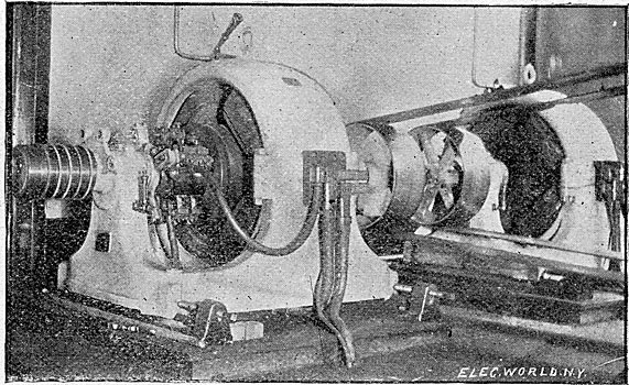
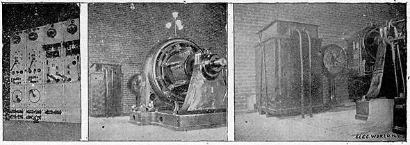
| Apparatus in Niagara Electro-Chemical Works. Fig. 2. - Switchboard for Rotary Transformers. Fig. 3. Static and Rotary Tran Rotary Transformers, 250 Kw Each, 2200 Volts, Alternating to 116 Volts, Direct-Current. Fig. 4. - Static Transformer, 2200 Volts, Two-Phase, to 118 Volts, Direct-Current. |
The current conveyed to the static transformers across this bridge by means of the cables shown is a two-phase alternating current of 2200 volts supplied by one of the 5000-hp generators. The illustration shows how they are carried on the sides of the subway from the generator on the left. On leaving the conductor bridge the cables are connected to the static transformers from below through the switchboard, which occupies a position on the left of the transformers as indicated.
It is a two-phase alternating-current switchboard of blue Vermont marble and has four single-pole switches on the upper part. The two-phase current at 2200 volts is then transformed to a three-phase current of 11,000 volts at the static transformers and is then conducted to the three-phase alternating switchboard, which is also of blue Vermont marble.
The static transformers are two in number and are mounted on an iron framework about eight feet from the cement floor of the transformer house. These transformers each have a capacity of 1250 horse-power and the expectation is to increase the number as rapidly as needed, the necessary space and arrangements having already been provided. The transformers are built with air-tight compartments below them, and the air is forced through by means of blowers, the amount being regulated by dampers fixed to the transformers themselves. The 5-hp motor operating a large centrifugal blower is shown in one of the illustrations. By means of this forced air circulation the efficiency of the transformers is kept very high, exceeding 98 per cent. and they, are at the same time kept absolutely cool even at full load, the temperature elevation not exceeding 40 degrees C.
In the pit below the transformers there is an abundance of room to walk about, and the connections are very easily made or broken at will. The lightning arresters are similar in design to those shown in the illustration of the Buffalo arresters and are located near the point where the cables leave the transformer house and are connected to the Buffalo, line. The cables from the transformers are mounted on porcelain insulators supported by iron brackets. The illustration shows the method of mounting in the subway of the transformer house before reaching the wood lightning arresters. The insulators are of the triple-petticoat type and were tested up to 50,000 volts, many puncturing at that voltage, particularly where flaws occurred in the glazing, but a perfectly glazed insulator always withstood the test.
There are several styles of insulators in use. The Niagara type was made by the Imperial Porcelain Works at Trenton, N. J.
After leaving the transformer house at Niagara Falls bare conductors are used and the current is thus conducted on an overhead pole line to the terminal house at Buffalo city limits. From the terminal house on the left bank of the canal, the conductors are carried underground after passing a set of single-pole switches in the building. From the terminal house the conductors, which are lead covered, pass through a conduit under the tow path of the canal to the transformer house of the Buffalo Street Railway Company.
THE BUFFALO STATIC TRANSFORMERS.
The transformer house of the Buffalo Street Railway Company is located at the rear of the main power-house and is partially underground. The conductors enter the transformer-house from beneath the static transformers and are, carried above them. The lightning arresters are shown in one of the accompanying illustrations and the connections to the transformers on the left. The three static transformers are mounted upon a framework similar to that at the Niagara transformer house, a space being left below the floor which is made air-tight and supplied by a 60-inch centrifugal blower. Air spaces are left between the laminations of the iron through which the air also passes. This method of cooling is neat and clean and seems to be far better than any other suggested as the air, which is forced through the transformers, comes in direct contact with the coils and laminations. The insulation of the coils is very good and the arrangement of them is such as to give the best protection against puncture.
| |||
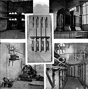
| Fig. 5. Beginning of Subway in Trans Former House Cables Carrying 3-Phase Current to Buffalo Line. Fig. 6. Centrifugal Blower Motor for 1250- HP Transformers. Fig. 7. 2200-Volt Two-Phase Switchboard. High Tension Fuses Below. Fig. 8.Two 1250-Horse-Power, Three-Phase 11,000-Volt Transformers. Fig. 9. Beginning of Subway Carrying 2200-Volt 2-Phase Current From 5000- HP Generators, Niagara Power-House. |
The three static transformers each have a capacity of 350 horsepower and the weight of each is over 7000 pounds. They have an efficiency of 98 per cent., and the temperature is not allowed to exceed 40 degrees centigrade. The transformers are 6 feet 9 inches high and each occupies a floor space of 4 square feet, or a total of from 12 to is square feet.
The three-phase alternating-current switchboard shown in one of the accompanying illustrations is similar to the three-phase board at the Niagara transformer house. It is made of blue Vermont marble, and upon it are mounted three large single-pole switches. The current is conducted by six cables to the rotary transformers in the power house. These cables together with an electric motor for driving one of the blowers is to be seen in one of the accompanying illustrations. The three-phase current on arrival at the transformer house h as a potential of a little more than 11,000 volts, and is transformed down to a low-pressure three-phase current and then through the rotary transformers to a current suitable for use on the street railway lines. Both rotary transformers have been in use since making the test and have given good satisfaction. They have been operated in parallel with old Edison bipolar generators which was a severe test. The rotaries have been operating the entire line during the night when the load was within their capacity, which is 1000 horse-power.
The Cold Spring and several other lines have been operated continuously up to the present time by the Niagara current, thereby showing that the Buffalo-Niagara transmission is a complete success. The Hon. Caryl Ely stated that the Buffalo & Niagara Falls Electric Railway Company was now operating the whole length of the line with Niagara current. It is the intention of the company, he said, to install a sub-station located midway between Buffalo and Tonawanda, which are to miles apart, and that in this station static and rotary transformers will be used for producing a 500-volt direct current. This will reduce the loss on the line and allow very much greater traffic with the present capacity of the feeders.
There is little doubt but that when the Buffalo Traction Company begins operations in Buffalo Niagara power will be used by this company also.
